
Related Manuals for Gooxi SL101-D04R


Summary of Contents for Gooxi SL101-D04R
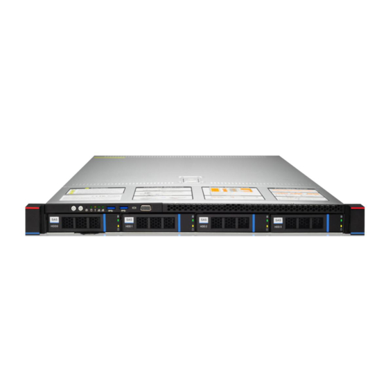
- Page 1 Purley Platform 1U L-shape Server Barebone SL101-D04R SL101-D10R User Manual V1.0...
- Page 2 Preface This user guide is the product technical manual of Purley 1U dual rackmount server. It mainly introduces and illustrates the technical characteristics, system architecture, installation and basic operation of the product. Purley 1U dual rackmount server has various models of 1U4/1U10-Bay. The product has the characteristics of low power consumption, flexible expansion, high reliability, easy management and deployment.
- Page 3 Disclaimers Gooxi provides this user Manual “Status Quo”. To the extent permitted by law, Gooxi does not provide any express or implied warranty and guarantee, including but not limited to commercial bestseller, applicability for a specific purpose, non...
- Page 4 Glossary: Noun Meaning Intel Xeon ® ® Scalable Processors Platinum Certified power supply is“80 PLUS Platinum”standard, that is, the Platinum Efficiency conversion rate of 20% load is above 90%, that of 50% load is more than 94%, Power Supply and that of 100% load is more than 91% M.
- Page 5 CMOS Complementary Metal Oxide Semiconductor 互补金属氧化物半导体 Management Engine 管理引擎 第四代双倍数据速率同步动态随机 DDR4 Double Data Rate 4 SDRAM 存储器 DIMM Dual-Inline-Memory-Modules 双列直插式存储模块 RDIMM Registered DIMM 带寄存器的双线内存模块 LRDIMM Load-Reduced DIMM 低负载 DIMM Apache Pass Intel 傲腾 DDR4 内存代号 ® MEZZ Mezzanine Connector 夹层/扣卡 CONN 通过直接连接键盘、视频、鼠标端...
-
Page 6: Table Of Contents
Contents CHAPTER I SAFETY INFORMATION ............................9 1.1 G ..............................9 ENERAL SAFETY PRECAUTIONS 1.2 T ..................10 OXIC AND HAZARDOUS SUBSTANCES OR ELEMENTS IN PRODUCTS 1.3 W ....................................11 ARNING 1.4 C ........................11 LIMATE AND ENVIRONMENTAL REQUIREMENTS ............................. 12 1.5 O THER IMPORTANT DESCRIPTIONS CHAPTER 2 PRODUCT INTRODUCTION .......................... - Page 7 5.2.1 Navigation Key Description .............................. 44 5.2.2 Main menu description ..............................44 5.2.3 Advanced menu description ............................... 46 5.2.4 Trusted Computing ................................48 5.2.5 Serial Port Console Redirection ............................49 5.2.6 Console Redirection Settings ............................. 50 5.2.7 SIO Configuration ................................52 5.2.8 [*Active*] Serial Port ................................
- Page 8 5.2.48 Save & Exit menu ................................101 5.3 U ..............................102 PERATION EMINDER CHAPTER 6 RAID SETUP INSTRUCTIONS ........................... 103 6.1 PCH RAID ................................. 103 CONFIGURES 6.1.1 Configuring RAID in UEFI Boot Mode .......................... 103 6.1.2 Configuring RAID in Legacy Boot Mode ........................110 6.2 RAID RAID .............................
-
Page 9: Chapter I Safety Information
Make sure the computer is well grounded. It can be grounded in different ways, but it is required to be actually connected to the ground. If you are not sure whether the safe grounding protection has been provided, please contact the corresponding organization or electrician for confirmation. If you need cable routing, please contact Shenzhen Gooxi Information Security Co.,Ltd. -
Page 10: Toxic And Hazardous Substances Or Elements In Products
Please keep the environment clean and avoid dust. The working temperature of the equipment is 10 ℃ ~ 40 ℃ and the humidity is 35% ~ 80%. Users are requested to back up important data in time. Shenzhen Gooxi Information Security Co., Ltd. is not responsible for data loss caused by any circumstances. -
Page 11: Warning
. However, it complies with the EU RoHS Directive (including its exemption provisions). Note: the table shows the information of toxic and hazardous substances in all possible components of Gooxi server, storage and workstation products. Customers can refer to the status of toxic and hazardous substances in all components of the purchased products according to this table. -
Page 12: Other Important Descriptions
Please do not disassemble the chassis, increase or decrease the hardware configuration of the server. Shenzhen Gooxi Information Security Co., Ltd. is not responsible for the hardware and data damage caused by this. When the server fails, please first check the "troubleshooting" section of this manual to determine and remove common faults. -
Page 13: Chapter 2 Product Introduction
SL101 series server barebone system is a new generation of 1U dual-socket rackmount server with a wide range of applications launched by Gooxi for the needs of Internet, IDC (Internet Data Center), cloud computing, enterprise market and telecom business applications. It is suitable for IT core business, cloud computing virtualization, high performance computing, distributed storage, big data processing, enterprise or telecom business applications and other complex workloads. - Page 14 System motherboard Model G3DCL-B processor and 2 Generation Intel Xeon Scalable Processors ® ® Number of Support 24 DDR4 memory slots memory slots Support DDR4 LRDIMM/RDIMM/NV-DIMM ECC memory Type of memory support Memory frequency supports 2133/2400/2666/2933MHz Memory size Support single capacity of 8GB, 16GB, 32GB, 64GB , 128G Hard disk 2* sSATA3.0 DOM, 3* MiniSAS 8643 ports interface...
-
Page 15: System Architecture
2.2.2 System Architecture Gooxi -SL101 series server is server barebones based on Intel Purley platform, the system supports 1U height, up to ® 205W CPU and up to 24 memories. This system uses a general motherboard named G3DCL-B, 1U4 front panel can support 4* 3.5-inch SATA/SAS hard disks, 1U10 front panel can support 10* 2.5-inch SATA/SAS hard disks. - Page 16 The system architecture motherboard block diagram: Figure 2- 1...
-
Page 17: Model Specification Introduction
2.3 Model specification introduction 1U4-bay 3.5-inch disk model Figure 2- 2 Product name SL101-D04R Processor Supports 1 or 2 Intel Xeon Scalable series processors, up to 205W Motherboard G3DCL-B model Chipset Intel ® C621 /C622 Series Server Chipsets Supports DDR4 LRDIMM/RDIMM/NV-DIMM ECC;... - Page 18 1U10 disk 3.5-inch disk model Figure 2- 3 Product name SL101-D10R Processor Supports 1 or 2 Intel Xeon Scalable series processors, up to 205W Motherboard G3DCL-B model Chipset Intel ® C621 /C622 Series Server Chipsets Supports DDR4 LRDIMM/RDIMM/NV-DIMM ECC; Memory frequency: 2133/2400/2666/2933MHz Memory Single CPU supports 6* DDR4 channels, each channel supports 2 slots,...
-
Page 19: Introduction Of System Components
2.4 Introduction of system components 2.4.1 Front Panel Components 1U4-bay 3.5-inch disk model Figure 2- 4 Serial Name Serial Name number number Left ear VGA interface Front Panel Indicators Right ear USB3.0 interface 3.5 inch hard drive Table 1- 7 1U10 disk 3.5-inch disk model ... - Page 20 Front Panel Indicators and Button Descriptions Figure 2- 6 Serial Serial Indicator/Button Indicator/Button number number Power switch button/indicator System alarm indicator Network port 1 connection status UID button/indicator indicator Network port 2 connection status Reset-server button indicator Hard disk indicator Table 1- 10 LED Status Description Logo...
-
Page 21: Rear Panel Components
turn on / off the positioning light. Reset server button Press to restart the server Blinking green light: The hard drive is operating Hard disk indicator normally System alarm indicator. Including system alarms, fan alarms, power supply alarms, etc., which can System alarm indicator be viewed through the IPMI management software... - Page 22 COM port Power Module 2 USB 3.0 interface Power module AC port 2 UID indicator Table 1- 12 Rear panel interface description Name Type Description For connecting to a display terminal such as a VGA interface DB15 monitor or KVM . Management Provide external 1000Mbit/s Ethernet port.
- Page 23 UID indicator Table 1- 14 Indicator / Button Status Description Green (steady on): Indicates that the input and output are normal. Red (steady on): Indicates that the input is normal, and there is no output due to power supply over-temperature protection, power output over-current/short-circuit, output over-voltage, short-circuit protection, device failure (excluding all device failures) and other reasons.
-
Page 24: Motherboard Components
2.4.3 Motherboard Components All models share motherboard components, the interface description is as follows 图 2- 9 Figure 2- 9... -
Page 25: Hdd Backplane Components
2.4.4 HDD Backplane Components 1U4 expansion backplane as shown: TOP surface Figure 2- 10 Serial Description Function number 1. Maximum 12G/b SAS hard disk; SAS/SATA hard drive 2. Maximum 6G/b SATA hard disk; connector 3. Support SAS/SATA hot-swap hard disk. Table 1- 16 Bottom surface Figure 2- 11... - Page 26 1U10 expansion backplane as shown TOP surface Figure 2- 12 Serial Description Function number 1. Maximum 12G/b SAS hard disk; SAS/SATA hard drive connector 2. Maximum 6G/b SATA hard disk; 3. Support SAS/SATA hot-swap hard disk. Table 1- 18 Bottom surface Figure 2- 13 Serial number...
- Page 27 PCIE X16 Spec Gold finger For connecting to PCI e X 16 interface Table 1- 20 OCP3.0 network card as shown in the figure Serial Description Function number It is mainly connected to the network interface controller of the motherboard CPU through PCIe Gen.2 X8, which is converted into a two-port optical port Intel 82599ES chip SFP+ at the network card end, and the 82599ES chip...
-
Page 28: Dimm Slot Locations
Green: 10 Gigabit Internet speed; Yellow: Gigabit network speed No light : no optical port network cable Green light for LAN1 data activity SFP+ LAN1 ACT LED Flashing : data activity ; off : no data activity Green/yellow indicator for LAN2 speed Green: 10 Gigabit network speed;... -
Page 29: Hard Disk Indicator
Figure 2- 17 2.4.7 Hard disk indicator Fault LED Status LED Act LED Figure 2- 18 Function Act LED Fault LED Status LEDs Hard drive in Always on place Hard drive activity Flashing 4Hz/sec Hard disk Always on Flashing 4Hz/sec positioning Hard disk error Always on... -
Page 30: Chapter 3 Installing System Components
Chapter 3 Installing System Components 3.1 Installation of CPU Install the processor: Step 1: CPU Installation 1. Tilt the CPU angle as shown in the figure, align the A1 angle (triangular mark), and clamp it on one end of the clamping piece. -
Page 31: Installation Of The Heat Sink
3.2 Installation of the heat sink Installation steps: 1. Remove the processor baffle (as shown below) Figure 3-5 2. Align the heat sink with the heat sink fixing studs on the CPU base, and tighten the heat sink fixing screws in sequence according to the instructions . -
Page 32: Memory Installation
3.3 Memory installation 3.3.1 Memory support specifications The motherboard supports 8GB/16GB/32GB R-DIMM, 32GB/64GB LR-DIMM, 128GB 3DS LRDIMM DDR4 memory, up to 2933MHz (2933MT/s can only be achieved with a single memory per channel, depending on the CPU SKU). Note: Please use memory modules with the same CAS delay value on this motherboard. It is recommended that you use the same capacity and the same frequency memory produced by the same manufacturer . - Page 33 Memory stick access principle: ( 2* CPUs) Amount of memory (Recommended: √ Not recommended: O ) √ √ √ √ √ √ √ Memory Processor Channel site CPU0 CPU1 Table 1-23 When installing 2 CPUs , in order to achieve optimal performance, it is recommended to install even number of memory, and the number of memory for each CPU remains the same;...
-
Page 34: Install Memory
3.3.2 Install memory 8 memory slots controlled by CPU 1 of the motherboard are: DIMMA1, A2, DIMMB1, B2, DIMM C1, C2 and DIMM D1, D2; the 8 memory slots controlled by CPU 2 are: DIMME1, E2, DIMMF1, F2, DIMMG1, G2 and DIMMH1, H2, pay attention to the notch of the memory and the notch of the DIMM slot, and snap each DIMM module into place vertically to prevent incorrect installation. -
Page 35: Hard Disk Installation
3.4 Hard disk installation Install 3.5" hard disk: 1. Put the hard disk in the tray 2. A total of 4 countersunk head screws on the left and right sides lock the hard disk (the screw heads must not protrude from the surface of the slideways on both sides of the tray) Figure 3- 10 Figure 3- 11... - Page 36 Install 2.5" hard disk: 1. Put the hard disk in the tray 2. 4 countersunk head screws at the bottom lock the hard disk (the screw heads protrude from the bottom of the tray) Figure 3- 12 Figure 3- 13 Install the hard disk tray components into the chassis: 1.
-
Page 37: Ssd Installation
3.5 M.2 SSD installation Step 1: Install the positioning studs according to the length of the M.2 card to be installed. Figure 3-15 Step 2: Install the M.2 Card 1. Insert the M.2 card connector end into the motherboard connector as shown in the illustration. 2. - Page 38 Figure 3- 17...
-
Page 39: Pcie Expansion Card Installation
3.6 PCIE expansion card installation Step: Install the PCIE Card 1. Insert the PCIE card in the direction shown in the figure 2. Rotate the PCIE card lock 3. According to the arrow plan, lock the PCIE card lock Figure 3- 18 3.7 PCIE module installation Riser1-3 module installing steps: PCIE components on the rear window, place them vertically downward - align with the PCIE slot, align with the positioning holes, and place them flush with the rear window. -
Page 40: Installation Of The Power Module
3.8 Installation of the power module Steps: Push the power supply to the end in the direction of the arrow, and after the spring wrench on the right makes a clicking sound, it means the installation is in place; Figure 3- 20 3.9 Installation of the fan module Steps: Place the fan module vertically downward in the direction of the arrow (pay attention to the direction of the fan module) -
Page 41: Installation Of The Wind Shield
3.1 0 Installation of the wind shield Steps: Align the Wind shield module with the hanging points on the left and right sides, and place it vertically downward - the height is lower than the height of the cabinet Figure 3- 22 3.11 Installation of the upper cover of the chassis Step 1: Install the case rear upper cover 1. -
Page 42: Chapter 4 System Rack Installation
Chapter 4 System Rack Installation 4.1 Inner guide rail installation Step 1. Prepare two slide rails and pull out the inner rail. Figure 4- 1 Step 2. Fasten the inner rails on both sides of the chassis. Figure 4- 2 4.2 Install the outer rails to the rack Step 3. -
Page 43: Install The Server Into The Rack
4.3 Install the server into the rack Step 4. Align the chassis with the inner rails installed on the outer rails for installation . Note: When you can push the chassis forward, you will hear a snap sound. If you can't push it, you need to pull the inner rail buckle down to continue to push the chassis gently. -
Page 44: Chapter 5 Bios Parameter Settings
Chapter 5 BIOS parameter settings 5.1 Enter the BIOS Setup interface Steps: 1. Power on the server motherboard and connect the keyboard; 2. During the POST process, pay attention to the prompt to enter the BIOS Setup interface at the bottom left of the Logo screen, "Press <DEL>... - Page 45 Figure 5- 1 BIOS Information Project Version: Displays the version information of the board BIOS. Build Date and Time: Displays the compilation date and time of the board BIOS. BMC Firmware Revision: Displays the version information of the board BMC. ME Firmware Version: Displays the version information of the board ME.
-
Page 46: Advanced Menu Description
CPU model information. PCH: PCH SKU and stepping information. RC Revision: Displays the version information of the board RC. Memory information Total Memory: Displays the total system memory capacity. Usable Memory: Displays the amount of available memory in the system. System Language: Select the current system language. - Page 47 Figure 5- 2 Trusted Computing Trusted Execution Module configuration. Serial Port Console Redirection Serial port redirection configuration. SIO Configuration Option ROM Dispatch Policy PCI Subsystem Settings CSM Configuration NVMe Configuration Network Stack Configuration iSCSI Configuration Intel Ethernet Connection X722 for xGbE - XX:XX:XX:XX:XX:XX Intel xG network card UEFI OPROM configuration...
-
Page 48: Trusted Computing
5.2.4 Trusted Computing Figure 5- 3 Display and set TCM/TPM module information. Different module options have different settings. Users can set according to the Setup help instructions. -
Page 49: Serial Port Console Redirection
5.2.5 Serial Port Console Redirection Figure 5- 4 Console Redirection The console redirection function switch redirects the information output from the console (such as a graphics card) to the display to the serial port. Disabled: Disable the redirection function. Enabled redirection. Default: Disabled... -
Page 50: Console Redirection Settings
5.2.6 Console Redirection Settings Figure 5- 5 Terminal Type This option selects the emulation type, the BIOS emulation type must match the mode selected in the terminal program. The menu options are: VT100 VT100+ VT-UTF8 ANSI Default: VT100+ Bits per second Serial port redirection rate, the value range is 9600~115200 Default: 115200 Data Bits... - Page 51 Odd: odd parity Mark: The check digit is always 1 Space: The check digit is always 0 Default: None Mark and Space checks are not allowed to detect errors. Stop Bits Serial port data packet end flag, the menu options are: Default: 1 Flow Control Serial port redirection control flow selection switch, the menu options are:...
-
Page 52: Sio Configuration
5.2.7 SIO Configuration Figure 5- 6... -
Page 53: Active*] Serial Port
5.2.8 [*Active*] Serial Port Figure 5- 7 Use This Device With this device, the menu options are: Enabled Disabled Default: Enabled Possible Select the optimal setting for the serial port according to your needs. The menu options are: Use Automatic Settings IO=3F8h;... -
Page 54: Option Rom Dispatch Policy
5.2.9 Option ROM Dispatch Policy Figure 5-8 Manage Option ROM call policy Restore if Failure To recover from a failure, the menu options are: Enabled Disabled Default: Disabled Primary Video Ignore Ignoring the base graphics card, the menu options are: Enabled Disabled Default: Enabled... -
Page 55: Pci Subsystem Settings
Disabled Default: Enabled On Board Display Controller Onboard or external device controller, the menu options are: Enabled Disabled Default: Enabled Slot # 1 Empty Onboard or external device controller, the menu options are: Enabled Disabled Default: Enabled Slot # 8 Empty Onboard or external device controller, the menu options are: Enabled Disabled... -
Page 56: Csm Configuration
The decoding control switch of memory space resources above 4G, the menu options are: Enabled Disabled Default value: Enabled SR-IOV Support SR-IOV supports switch settings, the menu options are: Enabled Disabled Default: Enabled 5.2.11 CSM Configuration Figure 5-10 CSM Support To enable or disable compatible support modules, the menu options are: Disabled Enabled... -
Page 57: Nvme Configuration
INT19 Trap Response Interrupt, capture signal response settings, the menu options are: Immediate: respond immediately Postponed: Delayed response Default: Immediate Boot option filter Startup option class control switch, the menu options are: UEFI and Legacy: UEFI and Legacy Boot Items UEFI only: UEFI Boot items Legacy only: Legacy Boot items Default: UEFI and Legacy... -
Page 58: Network Stack Configuration
Figure 5- 12 Displays detailed information about NVMe hard drives. 5.2.13 Network Stack Configuration... - Page 59 Figure 5- 13 Network Stack Network stack control switch, the menu options are: Enabled Disabled Default: Disabled IPv4 PXE Support Ipv4 UEFI PXE function control switch, the menu options are: Enabled Disabled Default: Disabled Ipv4 HTTP Support Ipv4 HTTP function control switch, the menu options are: Enabled Disabled Default: Disabled...
-
Page 60: Iscsi Configuration
5.2.14 iSCSI Configuration Figure 5- 14 iSCSI configuration 5.2.15 Platform Configuration menu... -
Page 61: Pch Sata Configuration
Figure 5- 15 PCH SATA Configuration PCH sSATA Configuration USB Configuration Miscellaneous Configuration Server ME Configuration Runtime Error Logging 5.2.16 PCH SATA Configuration Figure 5- 16 SATA Controller SATA controller switch, control to turn on and off the SATA controller, the menu options are: Disabled: Disable the SATA controller. - Page 62 SATA mode selection, the menu options are: AHCI: Select SATA mode as AHCI mode. RAID: Select SATA mode as RAID mode. Default: AHCI SATA test mode SATA test mode switch, the menu options are: Disabled Enable Default: Disable SATA Port X Displays device information on SATA Port 0~7, and displays Not Installed when no device is connected.
-
Page 63: Pch Ssata Configuration
5.2.17 PCH sSATA Configuration Figure 5- 17 sSATA Controller sSATA controller switch, control to turn on and off the sSATA controller, the menu options are: Disabled: Disable the sSATA controller. Enabled: Enable the sSATA controller. Default: Enabled Configure sSATA as sSATA mode selection, the menu options are: AHCI: Select sSATA mode as AHCI mode. -
Page 64: Usb Configuration
5.2.18 USB Configuration Figure 5- 18 USB Per-Connector Disable For each USB connector switch, the menu options are: Enable Disable Default: Disable XHCI Over Current Pins XHCI overcurrent pin switch, the menu options are: Enable Disable Default: Enable... -
Page 65: Miscellaneous Configuration
5.2.19 Miscellaneous Configuration Figure 5- 19 PCH state after G3 PCH state setting after G3, the menu options are: S0: Power on directly S5: You need to press the Power button to turn on the power leave power state unchanged: keep the power state unchanged Default: S0 Max Page Table Size Select To select the maximum page table size setting, the menu options are:... -
Page 66: Server Me Configuration
5.2.20 Server ME Configuration Figure 5- 20 Display Server ME version, features, status and other information; 5.2.21 Runtime Error Logging... -
Page 67: Socket Configuration Menu
Figure 5- 21 System Errors Turn on or off the system error function, the menu options are: Disabled Enabled Default: Enabled 5.2.22 Socket Configuration menu Figure 5- 22 Processor Configuration Common RefCode Configuration UPI Configuration Memory Configuration IIO Configuration Advanced Power Management Configuration... -
Page 68: Processor Configuration
5.2.23 Processor Configuration Figure 5- 23 Figure 5- 24 Display CPU Type\ID\Speed\Cache and other information, configure CPU-related functions;... - Page 69 Pre-Socket Configuration: each slot configuration; Hyper-Threading Hyper-Threading Control Switch, this option enables or disables the Hyper-Threading feature of Intel processors. When this feature is enabled, each physical processor core is equivalent to two logical processor cores; when this feature is disabled, each physical processor core is equivalent to only one logical processor core. Enabling this feature results in a higher processor core count, improving the overall performance of the application.
- Page 70 Enable Disable Default: Enable DCU Streamer Prefetcher DCU stream prefetch switch, the menu options are: Enable Disable Default: Enable DCU IP Prefetcher DCU IP prefetch switch, the menu options are: Enable Disable Default: Enable LLC Prefetcher LLC prefetch switch, the menu options are: Enable Disable Default: Disable...
-
Page 71: Common Refcode Configuration
5.2.24 Common RefCode Configuration Figure 5- 25 MMIO High Base Select the MMIO high base address, the menu options are: Default: 56T MMIO High Granularity Size To select the MMIO high interval size, the menu options are: 256G 1024G Default: 256G Numa To turn non-uniform memory access on or off, the menu options are: Enable... -
Page 72: Upi Configuration
5.2.25 UPI Configuration Figure 5- 26 UPI Status: UPI link status submenu, showing the current UPI link status Degrade Precedence When the system settings conflict, you can lower the feature by setting Topology Precedence, or lowering the Topology by setting Feature Precedence. The menu options are: Topology Precedence Feature Precedence Default: Topology Precedence... - Page 73 Auto Default: Auto UPI Failover Support UPI failover supports switch settings, the menu options are: Disable Enable Auto Default: Auto Sub NUMA cluster settings, the menu options are: Disable Enable Auto Default: Disable XPT Prefectch XPT prefetch settings, the menu options are: Disable Enable Auto...
-
Page 74: Memory Configuration
5.2.26 Memory Configuration Figure 5- 27 Enforce POR To enforce POR settings, the menu options are: Auto POR : execute POR Disable Default: Auto Memory Frequency Memory frequency setting, the menu options are: Auto 1000 1066 1200 1333 1400 1600 Default: Auto Data Scrambling for NVDIMMs NVDIMM data scramble switch settings, the menu options are:... - Page 75 Enable Default: Auto Data Scrambling for DDR4 DDR4 data scramble switch settings, the menu options are: Auto Disable Enable Default: Auto Enable ADR ADR enable switch setting, the menu options are: Disable Enable Default: Enable Legacy ADR Mode Traditional ADR mode switch settings, the menu options are: Disable Enable Default: Enable...
-
Page 76: Memory Topology
Memory topology submenu, showing in-place memory details; Memory Map Memory Map submenu; Memory RAS Configuration Memory RAS configuration submenu; 5.2.27 Memory Topology Figure 5- 28 Display current in-place memory details... -
Page 77: Memory Map
5.2.28 Memory Map Figure 5- 29 Volatile Memory Mode Volatile memory mode setting, the menu options are: Auto Default: Auto 1LM Memory Interleave Granularity 1LM memory interleaving interval setting, the menu options are: Auto 256B Target, 256B Channel 64B Target, 64B Channel Default: Auto IMC Interleaving IMC cross setting, the menu options are:... -
Page 78: Memory Ras Configuration
1-way Interleavel 2-way Interleavel 3-way Interleavel Default: Auto Rank Interleaving Rank cross setting, the menu options are: Auto 1-way Interleavel 2-way Interleavel 4-way Interleavel 8-way Interleavel Default: Auto Socket Interleave Below 4GB 4GB address space processor interleave switch settings, the menu options are: Enable Disable Default: Disable... - Page 79 Default: Disable Mirror Mode Mirror mode settings, the menu options are: Disable : disable Enable Mirror Mode (1LM) Default: Disable UEFI ARM Mirror UEFI ARM mirror mode switch settings, the menu options are: Enable Disable Default: Disable Memory Rank Sparing Memory Rank hot spare switch settings, the menu options are: Enable Disable...
-
Page 80: Iio Configuration
5.2.30 IIO Configuration Figure 5- 31 SocketN Configuration The SocketN configuration submenu is used to set the Link speed, Max Payload Size, ASPM and other settings of the device on the PCIE of CPU0, and display the link status of the current PCIE port, the maximum link, the current link rate, etc.;... -
Page 81: Advanced Power Management Configuration
Default: Per-Port PCI-E Max Read Request Size PCIE maximum read request size setting, the menu options are: Auto 128B 256B 512B 1024B 2048B 4096B Default: Auto 5.2.31 Advanced Power Management Configuration Figure 5- 32 CPU P State Control CPU P state control setting submenu; Hardware PM State Control Hardware power management state control submenu;... -
Page 82: Cpu P State Control
CPU-Advanced PM Tuning CPU performance and power saving tuning submenu; Socket RAPL Configuration Socket RAPL configuration submenu; 5.2.32 CPU P State Control Figure 5- 33 Uncore Freq Scaling (UFS) Uncore frequency extension settings, the menu options are: Enable Disable Default: Enable Config TDP TDP level settings, the menu options are: Normal... -
Page 83: Hardware Pm State Control
5.2.33 Hardware PM State Control Figure 5- 34 Hardware P-State The hardware selects whether the P-State state is actively set by the OS. The default value is determined according to the actual test. The menu options are: Disable : Hardware selects P-States based on legacy OS requests Native Mode: Hardware selection P-State based on legacy OS boot Out of Band Mode: Hardware is automatically selected, no OS boot required Native Mode with No Legacy Support... -
Page 84: Cpu C State Control
5.2.34 CPU C State Control Figure 5- 35 Autonomous Core C-State Autonomous core C state switch settings, the menu options are: Enable Disable Default: Disable CPU C6 report Reports the C6 status switch settings to the OS, the menu options are: Disable Enable Auto... -
Page 85: Package C State Control
5.2.35 Package C State Control Figure 5- 36 Package C State Package C status settings, the menu options are: C0/C1 state C2 state C6(non Retention) state C6(Retention) state No Limit Default: Auto... -
Page 86: Cpu-Advanced Pm Tuning
5.2.36 CPU-Advanced PM Tuning Figure 5- 37 Energy Perf BIAS CPU energy saving performance related options settings... -
Page 87: Energy Perf Bias
5.2.37 Energy Perf BIAS Figure 5- 38 Power Performance Tuning Energy saving performance adjustment settings, the menu options are: OS Controls EPB: OS Controls Power Saving Performance Tuning BIOS Controls EPB: BIOS Controls Power Saving Performance Tuning Default: OS Controls EPB ENERGY_PERF_BIAS_CFG Mode Energy-saving performance management settings, this can be set when Power Performance Tuning is set to BIOS Control EPB, the menu options are:... -
Page 88: Server Mgmt Menu
5.2.38 Server Mgmt Menu Figure 5- 39 Display BMC self-check status, device ID, device version, BMC software version, and version that supports IPMI specification. FRB-2 Timer FRB-2 clock switch settings, the menu options are: Enabled Disabled Default: Enabled FRB-2 Timer timeout FRB-2 clock timeout setting, the menu options are: 3 minutes 4 minutes... - Page 89 OS Watchdog Timer OS watchdog clock switch settings, the menu options are: Enabled Disabled Default: Disabled OS Wtd Timer timeout OS watchdog clock timeout setting, the menu options are: 5 minutes 10 minutes 15 minutes 20 minutes Default: 10 minutes OS Wtd Timer Policy The policy setting after the OS watchdog clock times out, the menu options are: Do Nothing...
-
Page 90: System Event Log Menu
5.2.39 System Event Log menu Figure 5- 40 SEL Components Start-up process system event recording function control switch, menu options: Enabled Disabled Default: Enabled Erase SEL Clear system event log control switch, menu options: No: do not clear Yes, On next reset Yes, On every reset Default: No When SEL is Full... -
Page 91: Bmc Network Configuration Menu
Default value: Error code 5.2.40 BMC network configuration menu Figure 5- 41... - Page 92 Figure 5- 42 Figure 5- 43 Configure IPV4 support BMC sharelink Management Channel Configuration Address source To configure the BMC IP address allocation mode, the menu options are: Unspecified: Do not change BMC parameters Static: BIOS static IP settings DynamicBmcDhcp: BMC runs DHCP to dynamically assign IP DynamicBmcNonDhcp: BMC runs Non-DHCP protocol to dynamically assign IP Default: Unspecified Modify the parameters from Unspecified to other parameters.
- Page 93 Modify the parameters from Unspecified to other parameters. After saving and restarting, the options will be restored to the Unspecified value, and there is no need to configure the BMC IP each time the startup process is performed. When the Configuration Address source option is Unspecified, it will display the network parameter information (IPV4) of the dedicated network port of the system, the current IP configuration method, BMC IP, subnet mask, MAC address, routing IP, routing MAC;...
-
Page 94: View System Event Log Menu
5.2.41 View System Event Log menu Figure 5- 44 View system event log information. Note that entering this menu, the BIOS needs to read the SEL data, and it needs to wait for a while. -
Page 95: Bmc User Setting
5.2.42 BMC User Setting Figure 5- 45 Add User Delete User Change User Setting... -
Page 96: Add User
5.2.43 Add User Figure 5- 46 User Name : User name setting, up to 16 characters are supported. User Password : User password settings, password characters must contain uppercase and lowercase letters, special characters and numbers, with a minimum of 8 characters and a maximum of 20 characters. Channel No : BMC channel setting, input 1 or 8 User Privilege Limit User permission settings, menu options are:... -
Page 97: Delete User
5.2.44 Delete User Figure 5- 47 User Name : Enter the user name to delete. User Password : Enter the password of the user to be deleted. After the correct password is entered, a prompt "User Delete!!!" will pop up. The successfully deleted user will take effect in the BMC immediately, and the user will not be able to log in to the BMC web interface. -
Page 98: Change User Setting
5.2.45 Change User Setting Figure 5- 48 User Name : Enter the user name to be modified. User Password : Enter to modify the user password, the following options can be modified only if the name and password are entered correctly. User User permission switch settings, menu options are: Enabled... -
Page 99: Security Menu
5.2.46 Security menu Figure 5- 49 Administrator Password Selects this option to set an administrator password; User Password Selects this option to set user password; Administrator Password Displays the administrator password status, if the system has an administrator password, it displays Installed; if there is no administrator password, it displays Not Installed;... -
Page 100: Boot Menu
5.2.47 Boot menu Figure 5- 50 Setup Prompt Timeout: Setup prompt timeout setting, set the time to wait for the Setup activation key, the maximum value is 65535 seconds, and the default value is 1. Bootup Numlock State During the boot process, the keyboard Numlock indicator light state switch setting, the menu options are: On : open OFF : off Default: On... -
Page 101: Save & Exit Menu
Boot Option Priorities The list of startup options, this list is displayed dynamically and is determined by the number of startup options in the system. When there is no startup item, it will not be displayed. XXXX Driver BBS Priorities XXXX device BBS priority setting 5.2.48 Save &... -
Page 102: User Operation Reminder
Restore user Defaults Boot Override A list of startup options, where a startup option can be selected. 5.3 User Operation Reminder 1.With option, when user operation is required, understand the operation specification in detail. 2. When operating options, please understand the meaning of the options in combination with the operation manual and the BIOS Setup interface option descriptions. -
Page 103: Chapter 6 Raid Setup Instructions
Chapter 6 RAID Setup Instructions 6.1 PCH configures RAID 6.1.1 Configuring RAID in UEFI Boot Mode Operation before configuring RAID 1. During the server startup process, press Delete/Esc as prompted to enter the BIOS Setup interface. 2. Move to the PlatForm page-->PCH Configuration-->PCH Sata Configuration-->Configure SATA as. Configure SATA to RAID mode, as shown in Figure 6-1. - Page 104 Figure 6- 2 4. Restart the server to enter the BIOS Setup interface, move to the Advanced page, you will see the Intel(R) RSTe SATA Controller, press enter to enter the RAID configuration, as shown in Figure 6-3 Figure 6-3 Intel RSTe SATA Controller Figure 6- 3...
- Page 105 Create RAID 1. Select Create RAID Volume and press enter. Figure 6-4 Figure 6-4 Create RAID Figure 6- 4 2. Change the name of the created RAID, being careful not to contain special characters. Figure 6-5 Figure 6-5 Create RAID name...
- Page 106 Figure 6- 5 3. RAID Level: Select the configuring RAID level, as shown in Figure 6-6, select the configuring RAID level Figure 6- 6 4. Select Disks: Press the space bar to select the disks that need to participate in configuring RAID. Figure 6-7 Figure 6-7 Selecting disks for configuring RAID...
- Page 107 Figure 6- 7 5. Select Create Volume and press Enter to configure the RAID. The relevant parameters are described in Table 1-36: Parameter Description Name The name of the RAID. RAID levels, which determine logical disk performance, fault tolerance, and RAID Level capacity.
- Page 108 Figure 6- 9 3. The interface shown in Figure 6-10 is displayed, select Yes, and press Enter to complete the configuration of the hot spare disk. Figure 6-10 Confirming the configuration of the hot spare disk Figure 6-10...
- Page 109 Delete RAID 1. Enter the RSTe configuration interface. 2. As shown in Figure 6-11, select the RAID to be deleted in the RAID Volumes directory, and press Enter. Figure 6-11 Selecting the RAID to be deleted Figure 6- 11 3. Enter the RAID information interface shown in Figure 6-12, select Delete, and press Enter to delete the RAID.
-
Page 110: Configuring Raid In Legacy Boot Mode
Figure 6- 12 6.1.2 Configuring RAID in Legacy Boot Mode Set RSTe working mode 1. Enter the BIOS Setup interface. 2. Move to the PlatForm page-->PCH Configuration-->PCH SATA Configuration... - Page 111 Figure 6- 13 The onboard soft RAID of RSTe has two controllers, SATA and sSATA, which manage the disks connected to the two interfaces of the RAID card respectively. The SATA controller supports up to 8 disks, and the sSATA controller supports up to 6 disks.
- Page 112 Figure 6- 15 If the working modes of both sSATA and SATA controllers are set to RAID, the prompt "Press <CTRL-I> to enter Configuration Utility" will appear twice during BIOS startup, corresponding to sSATA and SATA controllers in turn. Please configure RAID according to the The desired disk selection controller. 2.
- Page 113 Table 1-37 Description of the RSTe configuration interface Options Description On the upper side of the interface, you can perform the following tasks: 1.Create RAID Volume: Configure RAID volume. 2.Delete RAID Volume: Delete RAID volume. MAIN MENU 3.Reset Disks to Non-RAID: Clear the RAID configuration information of the disk.
- Page 114 Figure 6- 18 Table 1-38 Parameter description Parameter Description Name The name of the RAID. RAID level. RAID levels determine logical disk performance, fault tolerance, and RAID Level capacity. Select the member disks that make up the RAID. After selecting the Disks column, press Disks Enter, and press SPACE to select the disk.
- Page 115 Figure 6- 19 To configure a hot spare disk: 1. Enter the RSTe configuration interface. 2. As shown in Figure 6-20, select Mark Disks as Spare on the RSTe configuration interface, and press Enter. Figure 6-20 RSTe configuration interface...
- Page 116 Figure 6- 20 3. On the interface shown in Figure 6-21, select the disk to be configured as a hot spare disk and press SPACE to select it, then press Enter, enter y in the displayed prompt box, and press Enter to complete the hot spare disk configuration.
- Page 117 Figure 6- 22 Delete RAID: 1. Enter the RSTe configuration interface. 2. As shown in Figure 6-23, select Delete RAID Volume on the RSTe configuration interface, and press Enter. Figure 6-23 RSTe configuration interface...
-
Page 118: Raid Card Configures Raid
Figure 6- 23 3. Enter the interface shown in Figure 6-24, select the RAID to be deleted, and press Delete to complete the deletion. Figure 6-24 Selecting the RAID to be deleted Figure 6- 24 6.2 RAID card configures RAID 6.2.1 Configuring RAID in UEFI Boot Mode Enter the RAID card configuration interface 1. - Page 119 Figure 6- 25 Table 1-39 Parameter description Options Overview Select Configuration Management to perform tasks such as creating logical Configuration disks, viewing disk group properties, viewing hot spare information, and Management clearing configurations. Select Controller Management to view and manage controller properties and Controller Management perform tasks such as clearing controller events, scheduling and running controller events, and running patrol reads.
- Page 120 1. As shown in Figure 6-26, select Drive Management on the RAID card configuration interface, and press Enter. Figure 6-26 RAID card configuration interface Figure 6- 26 2. The interface shown in Figure 6-27 is displayed, select the disk to be configured, and press Enter. Figure 6-27 Drive Management management interface...
- Page 121 Figure 6- 27 3. Enter the interface shown in Figure 6-28, select Operation, and press Enter. In the displayed dialog box, select Make Unconfigured Bad, and press Enter. Figure 6-28 Operation interface Figure 6- 28 4. Enter the interface shown in Figure 6-29, select Go, and press Enter. Figure 6-29 Select Go...
- Page 122 Figure 6- 29 5. Enter the interface shown in Figure 6-30 and complete the operation of switching the disk mode. Figure 6-30 Complete switching disk mode Figure 6- 30...
- Page 123 Create RAID: 1. As shown in Figure 6-31, select Configuration Management on the RAID card configuration interface, and press Enter. Figure 6-31 RAID card configuration interface Figure 6- 31 2. Enter the interface shown in Figure 6-32, select Create Virtual Drive, and press Enter. Figure 6-32 Select Create Virtual Drive...
- Page 124 Figure 6- 32 3. On the interface shown in Figure 6-33, select Select RAID Level, set the RAID level, and press Enter. Figure 6-33 Setting the RAID level Figure 6- 33...
- Page 125 4. Enter the interface shown in Figure 6-34, select Select Drives From, set the RAID disk capacity source, and press Enter. [Unconfigured Capacity] indicates that the capacity comes from the remaining capacity of the RAID-configured disk. [Free Capacity] indicates that the capacity comes from an empty disk. Figure 6-34 Setting the disk capacity source of RAID Figure 6- 34 5.
- Page 126 Figure 6- 35 6. Enter the interface shown in Figure 6-36, select the disk to be used to configure RAID, [Enabled] means selected, then select Apply Changes, and press Enter. If the status of the disk is JBOD or Unconfigured Bad, it cannot be selected.
- Page 127 7. Enter the interface shown in Figure 6-37, make corresponding settings (see Table 1-32 for parameter descriptions), select Save Configuration, and press Enter. Figure 6-37 Setting RAID parameters Figure 6- 37 Parameter Description Parameter Description The name of the RAID, only supports letters, numbers and underscores, Virtual Drive Name case-insensitive Virtual Drive Size...
- Page 128 Do not use special characters as RAID names. Compared with No Read Ahead, Write Through, and Direct, Read Ahead, Write Back, and Cached have improved performance, but data consistency cannot be guaranteed. If the supercapacitor is abnormal, when the write cache policy is set to "Write Back", the firmware will implement ...
- Page 129 Figure 6- 39 10. As shown in Figure 6-40, select Virtual Drive Management on the RAID card configuration interface, and press Enter. Figure 6-40 RAID card configuration interface Figure 6- 40...
- Page 130 11. On the interface shown in Figure 6-41, you can see the created RAID, select the RAID to be viewed, and press Enter. Figure 6-41 Virtual Drive Management interface Figure 6- 41 12. Enter the interface shown in Figure 6-42, select View Associated Drives, and press Enter to view the detailed information of the RAID (including RAID name, level, and disk information, etc.).
- Page 131 Figure 6- 42 To configure a hot spare disk: After configuring RAID, a hot spare disk is generally configured to improve data security. A global hot spare disk or a dedicated hot spare disk can be configured as required. Hot spares are only used for RAID levels where redundancy exists. ...
- Page 132 Figure 6- 43 2. On the interface shown in Figure 6-44, select the disk to be configured as a global hot spare, and press Enter. Figure 6-44 Drive Management management interface Figure 6- 44...
- Page 133 3. On the interface shown in Figure 6-45, select Operation, press Enter, then select Assign Dedicated Hot Spare Drive, and press Enter. Figure 6-45 Operation interface Figure 6-45 4. Enter the interface shown in Figure 6-46, select Go, and press Enter. Figure 6-46 Select Go...
- Page 134 Figure 6- 46 5. Enter the interface shown in Figure 6-47, select Confirm to enable it, select Yes, and press Enter. Figure 6-47 Confirm the configuration Figure 6- 47 6. Enter the interface shown in Figure 6-48 and complete the operation of configuring the global hot spare disk. Figure 6-48 Complete the configuration of the global hot spare disk...
- Page 135 Figure 6- 48 Delete RAID: 1. As shown in Figure 6-49, select Virtual Drive Management on the RAID card configuration interface, and press Enter. Figure 6-49 RAID card configuration interface Figure 6- 49 2. The interface shown in Figure 6-50 is displayed, select the logical disk to be deleted, and press Enter. Figure 6-50 Logical disk management interface...
- Page 136 Figure 6- 50 3. On the interface shown in Figure 6-51, select Operation and press Enter. In the displayed dialog box, select Delete Virtual Drive and press Enter. Figure 6-51 Operation interface Figure 6-51...
- Page 137 4. Enter the interface shown in Figure 6-52, select Go, and press Enter. Figure 6-52 Select Go Figure 6-52 5. Enter the interface shown in Figure 6-53, select Confirm to enable it, select Yes, and press Enter. Figure 6-53 Confirm deletion...
- Page 138 Figure 6-53 6. The interface shown in Figure 6-54 is displayed, and the RAID deletion operation is completed. Figure 6-54 Complete the deletion of RAID Figure 6-54 Locate disk location: 1. Locate physical disks As shown in Figure 6-55, select Drive Management on the RAID card configuration interface, and press Enter. Figure 6-55 Select Drive Management...
- Page 139 Figure 6-55 2. On the interface shown in Figure 6-56, select the disk to be located, and press Enter. Figure 6-56 Select the disk to be located Figure 6-56...
- Page 140 3. On the interface shown in Figure 6-57, select Operation, and press Enter. In the displayed dialog box, select Start Locate and press Enter. Figure 6-57 Operation interface Figure 6-57 4. Enter the interface shown in Figure 6-58, select Go, and press Enter. Figure 6-58 Select Go...
- Page 141 Figure 6-58 5. Enter the interface shown in Figure 6-59 and complete the operation of locating the physical disk. Figure 6-59 Complete physical disk location positioning Figure 6-59 Locate all disks in a logical disk 1. As shown in Figure 6-60, select Virtual Drive Management on the RAID card configuration interface, and press Enter.
- Page 142 Figure 6- 60 2. On the interface shown in Figure 6-61, select the logical disk to be located, and press Enter. Figure 6-61 Selecting the logical disk to be located Figure 6-61...
- Page 143 3. On the interface shown in Figure 6-62, select Operation and press Enter. In the displayed dialog box, select Start Locate and press Enter. Figure 6-62 Operation interface Figure 6-62 4. Enter the interface shown in Figure 6-63, select Go, and press Enter. Figure 6-63 Select Go...
- Page 144 Figure 6- 63 5. Enter the interface shown in Figure 6-64, and complete the operation of locating all disk locations in the logical disk. Figure 6-64 Complete the positioning of all disks in the logical disk Figure 6- 64 Initialize the logical disk: This function is used to initialize the internal data space of the logical disk so that it can be recognized and used by the operating system.
- Page 145 Figure 6- 65 2. On the interface shown in Figure 6-66, select the logical disk to be initialized, and press Enter. Figure 6-66 Logical disk management interface Figure 6- 66...
- Page 146 3. Enter the interface shown in Figure 6-67, select Operation, and press Enter. In the dialog box that pops up, select Fast/Slow Initialization and press Enter. Figure 6-67 Operation interface Figure 6- 67 Description: The difference between Fast Initialization and Slow Initialization is that the former can write data immediately, while the latter needs to wait for all the disk space to be initialized before writing data.
- Page 147 Figure 6- 68 5. Enter the interface shown in Figure 6-69, select Confirm to enable it, select Yes, and press Enter. Figure 6-69 Confirm initialization Figure 6- 69 6. Enter the interface shown in Figure 6-70 to complete the initialization of the logical disk.
- Page 148 Figure 6-70 Complete the initialization of the logical disk Figure 6- 70 Initialize the physical disk: 1. As shown in Figure 6-71, select Drive Management on the RAID card configuration interface, and press Enter. Figure 6-71 RAID card configuration interface...
- Page 149 Figure 6- 71 2. Enter the interface shown in Figure 6-72, select the disk to be initialized, and press Enter. Figure 6-72 Disk management interface Figure 6- 72 3. On the interface shown in Figure 6-73, select Operation, and press Enter. In the displayed dialog box, select Initialize Drive and press Enter.
- Page 150 Figure 6- 73 4. Enter the interface shown in Figure 6-74, select Go, and press Enter. Figure 6-74 Select Go Figure 6- 74 5. Enter the interface shown in Figure 6-75, select Confirm to enable it, select Yes, and press Enter.
- Page 151 Figure 6-75 Confirm initialization Figure 6- 75 6. Enter the interface shown in Figure 6-76 to complete the initialization of the physical disk. Figure 6-76 Complete the initialization of the physical disk Figure 6- 76...
- Page 152 Erase disk data: This function is used to delete data inside the disk, including erasing physical disk data and logical disk data. Erase physical disk data 1. As shown in Figure 6-77, select Drive Management on the RAID card configuration interface, and press Enter. Figure 6-77 RAID card configuration interface Figure 6- 77 2.
- Page 153 Figure 6- 78 3. Enter the interface shown in Figure 6-79, select Operation, press Enter, then select Drive Erase in the displayed dialog box, and press Enter. Figure 6-79 Operation interface Figure 6- 79...
- Page 154 4. Enter the interface shown in Figure 6-80, press Enter, and then select the erase mode in the pop-up dialog box (the default mode is recommended: Simple). Figure 6-80 Erase Mode interface Figure 6- 80 5. Enter the interface shown in Figure 6-81, select Go, and press Enter. Figure 6-81 Select Go...
- Page 155 Figure 6- 81 6. Enter the interface shown in Figure 6-82, select Confirm to enable it, select Yes, and press Enter. Figure 6-82 Confirm Erase Figure 6- 82 7. Enter the interface shown in Figure 6-83 and complete the operation of erasing the physical disk data. Figure 6-83 Complete erasing physical disk data...
- Page 156 Figure 6- 83 Description: To avoid disk failure, do not perform other operations while erasing physical disk data. Erase Logical Disk Data 1. As shown in Figure 6-84, select Virtual Drive Management on the RAID card configuration interface, and press Enter. Figure 6-84 RAID card configuration interface Figure 6-84 2.
- Page 157 Figure 6- 85 3. Enter the interface shown in Figure 6-86, select Operation, and press Enter. In the displayed dialog box, select Virtual Drive Erase and press Enter. Figure 6-86 Operation interface Figure 6-86...
- Page 158 4. Enter the interface shown in Figure 6-87, press Enter, and then select the erase mode in the pop-up dialog box (the default mode is recommended: Simple). Figure 6-87 Erase Mode interface Figure 6- 87 5. Enter the interface shown in Figure 6-88, select Go, and press Enter. Figure 6-88 Select Go...
- Page 159 Figure 6- 88 6. Enter the interface shown in Figure 6-89, select Confirm to enable it, select Yes, and press Enter. Figure 6-89 Confirm Erase Figure 6- 89 7. Enter the interface shown in Figure 6-90 and complete the operation of erasing the logical disk data. Figure 6-90 Completion of erasing logical disk data...
- Page 160 Figure 6- 90 Migrating RAID levels: This function is used to modify the RAID level to meet the configuration requirements without affecting the current data integrity. 1. As shown in Figure 6-91, select Virtual Drive Management on the RAID card configuration interface, and press Enter.
- Page 161 Figure 6- 92 3. Enter the interface shown in Figure 6-93, select Operation, and press Enter. In the displayed dialog box, select Reconfigure Virtual Drive, and press Enter. Figure 6-93 Operation interface Figure 6- 93...
- Page 162 4. Enter the interface shown in Figure 6-94, select Go, and press Enter. Figure 6-94 Select Go Figure 6- 94 5. On the interface shown in Figure 6-95, set the RAID level, select Add Drives, and press Enter. Figure 6-95 Advanced interface...
- Page 163 Figure 6- 95 6. On the interface shown in Figure 6-96, select the disk to be added, make it Enabled, select Apply Changes, and press Enter. Figure 6-96 Add Drives interface Figure 6- 96 7. Enter the interface shown in Figure 6-97, select Confirm to enable it, select Yes, and press Enter. Figure 6-97 Confirm migration...
- Page 164 Figure 6- 97 8. On the interface shown in Figure 6-98, select Start Operation, and press Enter. Figure 6-98 Start Operation interface Figure 6- 98 9. Enter the interface shown in Figure 6-99, select OK, and press Enter.
- Page 165 Figure 6-99 Select OK Figure 6- 99 10. On the interface shown in Figure 6-100, you can view the current migration progress. Figure 6-100 RAID information interface Figure 6- 100...
- Page 166 Clear disk RAID information: This function is used to clear the residual RAID information in the disk, so that the disk can be reused for RAID configuration. This function is often used for disks whose mode is Unconfigured Bad. 1. Switch the disk mode Unconfigured Bad to Unconfigured Good. 2.
- Page 167 Figure 6- 102 4. Enter the interface shown in Figure 6-103, select Clear Foreign Configuration, and press Enter. Figure 6-103 Select Clear Foreign Configuration Figure 6- 103 5. Enter the interface shown in Figure 6-104, select Confirm to enable it, select Yes, and press Enter.
- Page 168 Figure 6- 104 6. Enter the interface shown in Figure 6-105 and complete the operation of clearing disk RAID information. Figure 6- 105...
-
Page 169: Configuring Raid In Legacy Boot Mode
6.2.2 Configuring RAID in Legacy Boot Mode Enter the RAID card configuration interface 1. During the BIOS startup, when the interface shown in Figure 6-105 is displayed, press Ctrl+R. Figure 6-106 Press Ctrl+R according to the prompt during BIOS startup Figure 6- 106 2. - Page 170 Figure 6- 107 Common tasks Configure RAID: 3. As shown in Figure 6-108, press F2 on the VD Mgmt interface and select Create Virtual Drive. Figure 6-108 Select Create Virtual Drive...
- Page 171 Figure 6- 108 4. Enter the interface shown in Figure 6-109, set the RAID level, and press Enter. Figure 6-109 Setting the RAID level Figure 6- 109 5. The interface shown in Figure 6-110 is displayed, select the disk for configuring RAID, and press Enter. Figure 6-110 Select disk...
- Page 172 Figure 6- 110 6. Enter the interface shown in Figure 6-111, set the Size and Name accordingly, select Advanced, and press Enter. Figure 6-111 Setting the RAID name and capacity Figure 6- 111 7. Enter the interface shown in Figure 6-112, set relevant parameters, select OK, and press Enter. Figure 6-112 Setting advanced parameters...
- Page 173 Figure 6- 112 8. Enter the interface shown in Figure 6-113, select OK, and press Enter to complete the RAID configuration operation. Figure 6-113 Confirm creation Figure 6- 113...
- Page 174 9. Select the RAID to be viewed and press Enter to view the detailed information of the RAID (including the RAID name, level, and disk information), as shown in Figure 6-114. Figure 6-114 Viewing RAID information Figure 6- 114 To configure a hot spare disk: After configuring RAID, a hot spare disk is generally configured to improve data security.
- Page 175 Figure 6- 115 2. Enter the interface shown in Figure 6-116, select Make Global HS, and press Enter to complete the configuration of the global hot spare disk. Figure 6-116 Select Make Global HS Figure 6- 116...
- Page 176 3. Return to the interface shown in Figure 6-117 and select a hot spare to view information about the global hot spare. Figure 6-117 Viewing global hot spare disk information Figure 6- 117 Remove RAID: This function is used to delete RAID that is damaged or difficult to meet your needs. 1.
- Page 177 Figure 6- 118 2. Enter the interface shown in Figure 6-119, select Delete VD, and press Enter. Figure 6-119 Select Delete VD Figure 6- 119 3. The interface shown in Figure 6-120 is displayed, select YES, and press Enter to complete the RAID...
- Page 178 deletion operation. Figure 6-120 Confirm deletion Figure 6- 120 Locate the disk location: This function makes it easy for you to quickly find the disk by lighting the blue indicator of the corresponding slot of the disk. A single physical disk or all member disks included in a logical disk can be located. 1.
- Page 179 Figure 6- 121 2. Enter the interface shown in Figure 6-122 and select Locate->Start to complete the disk location operation. Figure 6-122 Select Locate- >Start Figure 6- 122...
- Page 180 Locate->Start: Start the disk location operation. Locate->Stop: Stop the locating disk operation. Initialize the logical disk: This function is used to initialize the internal data space of the disk so that it can be recognized and used by the operating system.
- Page 181 Figure 6- 124 BGI: Backgroud Initialization, background initialization, first initialize part of the RAID space for writing data, and the rest of the space is initialized in the background. FGI: Full Groud Initialization, the whole disk is initialized, all the space of the RAID is initialized, and the data can be written after the initialization is completed.
- Page 182 Figure 6- 125 Erase disk data: This function is used to delete data inside the disk, including erasing physical disk data and logical disk data. Erase physical disk data 1. As shown in Figure 6-126, select the physical disk to be erased on the PD Mgmt interface, and press F2. Figure 6-126 Select the physical disk to be erased Figure 6- 126...
- Page 183 2. Enter the interface shown in Figure 6-127, select the erase mode (the default mode is recommended: Simple), and press Enter. Figure 6-127 Select Erase Mode Figure 6- 127 3. Enter the interface shown in Figure 6-128, select Yes, and press Enter to complete the operation of erasing the physical disk data.
- Page 184 To avoid disk failure, do not perform other operations while erasing physical disk data. Erase Logical Disk Data 1. As shown in Figure 6-129, select the logical disk to be erased on the VD Mgmt interface, and press F2. Figure 6-129 Select the logical disk to be erased . Figure 6- 129 2.
- Page 185 Figure 6- 130 3. Enter the interface shown in Figure 6-131, select Yes, and press Enter to complete the operation of erasing the logical disk data. Figure 6-131 Confirm Erase Figure 6- 131...
- Page 186 Clear disk RAID information: This function is used to clear the residual RAID information in the disk, so that the disk can be reused for RAID configuration. This function is often used for disks whose mode is Unconfigured Bad. 1. Switch the disk mode Unconfigured Bad to Unconfigured Good. 2.
- Page 187 Figure 6- 133...
-
Page 188: Chapter 7 Ipmi Rapid Deployment
Chapter 7 IPMI Rapid Deployment 7.1 Rapid Deployment of IPMI Process Figure 7-1 shows the general process of how to quickly deploy the IPMI function of the server. Figure 7-1 IPMI deployment process 7.1.1 Make sure the motherboard supports the IPMI function Check your motherboard manual and confirm that your motherboard supports IPMI, and then find the dedicated IPMI network port for the motherboard, or you can choose a shared network port, as shown in Figure 7-2. - Page 189 Figure 7-3 Motherboard BIOS setting interface After entering this interface, use the left and right keys on the keyboard to switch the menu item to the Server Mgmt option, and you will see the page shown in Figure 7-4. Figure 7-4 Server Mgmt interface After entering this interface, enter the BMC network configuration option through the keyboard, and you will enter the following interface, as shown in Figure 7-5.
- Page 190 Figure 7-5 BMC network configuration option interface On this page, you can see two configurable network ports, one is the dedicated network port for Dedicated, and the other is the shared network port for Sharelink. Take the shared network port as an example here. If you connect a dedicated network port, the setting method is the same as the shared network port.
-
Page 191: Ipmi Port Configuration Static Mode
Figure 7-6 Configuring the network port network mode There are four network modes that can be configured on this interface, namely Unspecified, Static, DynamicBMCDHCP, and DynamicBMCNonDHCP. Static is the static mode, you can manually set the IP address, and DHCP is the dynamic mode. Setting this item allows the BMC to automatically obtain the IP address from the DHCP server. -
Page 192: Quick Start Instructions For Ipmi Functions
Switch to the Advanced menu, select Serial Port Console Redirection, and press <Enter>. Make sure that the Console Redirection of COM0 is in the [Enabled] state, if not, select Console Redirection, and then press the <Enter> key to set the state to [Enabled]. To ensure the normal operation of iBMC, this option is set to [Enabled] by default. -
Page 193: Default Username And Password
7.2.2 Default Username and Password Factory default username: admin Factory default password: admin When you log in with this username, you will have full administrator rights. It is recommended that you change the password after logging in. 7.2.3 Contents of IPMI Management System After you log in to the IPMI management system correctly, you can see the page shown in Figure 7-10. -
Page 194: Introduction To Kvm Remote Management
BMC can be configured in this menu. Including BSOD, date & time, network, etc... (7) Remote control On this page, KVM, SOL can be started, and power control and UID (server logo light) control can also be performed. (8) Mirror redirection On this page, you can get the latest image file on the remote storage device. -
Page 195: Remote Control Shortcut Operation
Shortcut bar Server remote screen display Figure 7-13 Composition of KVM interface 7.2.6 Remote control shortcut operation Stop KVM Hanging on the CD image, generally used to remotely install the operating system The host display is unlocked, the server is turned on/off Table 1- 41 7.2.7 Introduction to SOL... - Page 196 Figure 7-14 Enabling Java SOL 1. After clicking to activate, the SOL interface shown in Figure 7-15 will appear. 2. Press Enter to activate the screen.
-
Page 197: Other Ways To Connect To Ipmi
Figure 7-15 SOL operation interface Note: The SOL interface operation function has only been tested for BIOS screen synchronization, and other interfaces have not been tested. This time is an operation demonstration and will not be described in detail. 7.3 Other ways to connect to IPMI The AST2500 firmware complies with the IPMI 2.0 specification, so users can use the standard IPMI driver assigned by the operating system. - Page 198 Front: 1 VGA, 2 USB3.0 Rear: 1 VGA, 2 USB3.0, 1 management network port, 2 RJ45 network External port ports &PCIE PCIE expansion: up to 10* PCIE expansion slots OCP slot: 1 OCP 3.0 (X8) Standard 7* 4056 hot-swap fans Network Onboard 2* 1GbE or 10GbE (RJ45) TPM/TCM (optional)
Need help?
Do you have a question about the SL101-D04R and is the answer not in the manual?
Questions and answers