
Subscribe to Our Youtube Channel
Related Manuals for Gooxi SL201


Summary of Contents for Gooxi SL201
- Page 1 SL201-G4 Rackmount Server User Manual Document version:01 Release date:2023/11/07 Shenzhen Gooxi Information Security Co., Ltd.
-
Page 2: Statement
Gooxi provides this user manual "as is" and to the extent permitted by law, makes no express or implied warranties or guarantees, including but not limited to merchantability, fitness for a particular purpose, non-infringement of any rights of others, and any warranties or guarantees regarding the use or inability to use this user manual. -
Page 3: Foreword
Foreword This manual is the product technical manual for the Gooxi Eagle Stream platform 2U model servers. It primarily provides an introduction and explanation of the product's appearance, structure, hardware installation, and basic configuration. Please note that this manual is intended for reference and research purposes for professional technical personnel. -
Page 4: Table Of Contents
Contents Statement..............................1 Foreword..............................2 1. Product Introduction ........................5 1.1 Product Overview ......................... 5 1.2 Product Structure ........................6 1.3 Logical Structure ........................7 1.4 Product Specifications ......................8 2. Hardware Description ........................10 2.1 Front Panel ..........................10 2.1.1 Appearance ........................10 2.1.2 Indicator lights and buttons ..................... - Page 5 4.1.1 Power on and start ......................35 4.1.2 Initial data ........................37 4.1.3 Configure BIOS ....................... 37 4.1.4 Configure BMC ....................... 38 Appendix............................43...
-
Page 6: Product Introduction
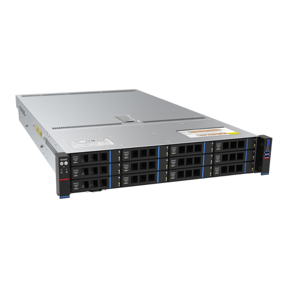
1.1 Product Overview SL201-G4 Series 2U Dual-socket Rack-Mount Server is a new generation of versatile 2U dual-socket rack-mount servers launched by Gooxi to meet the needs of the Internet, IDC (Internet Data Center), cloud computing, enterprise markets, and telecom business applications. It is suitable for core IT operations, cloud computing virtualization, high-performance computing, distributed storage, large-scale data processing, enterprise or telecom business applications, and other complex workloads. -
Page 7: Product Structure
1.2 Product Structure SL201 Eagle Stream 2U Dual-Socket Server has variations in configuration based on different requirements. Taking the 8-drive model as an example, the description of various components of the server is as shown in the following diagram: Structure diagram 1-3... -
Page 8: Logical Structure
1.3 Logical Structure The logic of the SL201-G4 Series Dual-Socket Rack-Mount Server is as shown in the following diagram: Motherboard logic block diagram 1-4 The CPU adopts the 4th generation Intel Xeon Scalable processor, LGA4677 socket. Each CPU supports 8 channels, and each channel supports 2 DDR5 ... -
Page 9: Product Specifications
1.4 Product Specifications SL201-D12R-G4 Product Series SL201-D08R-G4 SL201-D12RE-G4 SL201-D25RE-G4 SL201-D12R-NV-G4 2U 8-bay 2U 12-bay 2U 25-bay Product Type 799*433.4*87.6mm (depth*width*height) System Size Supports 1 or 2 4th generation Intel® Xeon® Scalable processors Processor 32 DDR5 memory slots, supporting DDR5 RDIMM-3DS/RDIMM 4400/4800 Memory MHz;... - Page 10 Management 1 dedicated RJ45 management port Port RoHS Compliant with RoHS2.0 Working Temperature 5℃~35℃/humidity 20%~80% RH non-condensing Temperature& Humidity Short-term storage (≤72 hours): Temperature -40°C ~ 70°C / Humidity 20% Storage ~ 90% RH (non-condensing, including packaging) Temperature& Long-term storage (>72 hours): Temperature 20°C ~ 28°C / Humidity 30% ~...
-
Page 11: Hardware Description
2. Hardware Description 2.1 Front Panel 2.1.1 Appearance 8x3.5-inch hard drive configuration Figure 2-1 Name Name DVD optical drive USB3.0 interface VGA interface 3.5-inch hard drive Table 2-1 12x3.5-inch hard drive configuration Figure 2-2 Name Name 3.5-inch hard drive USB3.0 interface VGA interface Table 2-2... -
Page 12: Indicator Lights And Buttons
2.1.2 Indicator lights and buttons Figure 2-4 Indicator light/button Indicator light/button Power switch System Alarm Indicator button/indicator UID button/indicator Network port 1 connection status indicator Reset server button Network port 2 connection status indicator Hard drive indicator LED status description Indicator Logo Status description... -
Page 13: Interface
Hard drive Blinking green light: The hard drive is operating indicator normally System warning indicator. Including system alarms, System Alarm fan alarms, power supply alarms, etc., which can be Indicator viewed through the IPMI management software Corresponds to the Ethernet port indicator of the network card. -
Page 14: Rear Panel
2.2 Rear Panel 2.2.1 Appearance Appearance of the rear panel Figure 2-6 Name Name Riser1 module Riser2 module Riser3 module Riser4 module OCP network card slot OCP network card slot Power module 1 Power module 2 Table 2-7 Note: 1. -
Page 15: Interface
Green (steady on): Indicates that the input and output are normal. Orange (steady on): Indicates that the AC power cord is unplugged or the power module is missing, and only one parallel-connected power module has AC input; the power module failure causes the output to be turned off, such as OVP, OCP, fan failure, etc. -
Page 16: Processor
When configuring with 1 processor, it should be installed in CPU 0 position. Processors installed in the same server must have the same model. For specific optional system configurations, please consult Gooxi sales. Processor positions are as shown in the following diagram: ... -
Page 17: Memory
2.4 Memory 2.4.1 Memory slot location This motherboard adopts the Intel Eagle Stream platform. Each CPU supports 8 channels, and each channel supports 2 DDR5 memories. The motherboard can support 32 DIMM DDR5 memories. When inserting only one memory, prioritize A0, B0, C0, D0, E0, F0, G0, H0 (memory slots with blue plastic color). -
Page 18: Memory Compatibility Information
2.4.2 Memory Compatibility Information The motherboard supports DDR5 RDIMM/RDIMM-3DS server memory, and the memory frequency is supported at 4400/4800MHz: Note: The same server must use the same model of DDR5 memory, and the operating speed of all memories must be the same, with the speed value being the minimum of the following: The memory speed supported by the specific CPU. -
Page 19: Hard Drive Serial Number
Configuration NVMe/SAS/SATA -Supports NVMe/SAS/SATA ATA hard hard drives hard drives drives require different cable support; SAS hard drives require the option of pass-through cards or RAID cards for support. Riser2 module(2x3.5/2.5)*2 -Supports SAS/SATA hard Requires Front Hard Drive drives 12x3.5-inch optional SAS (12x3.5/2.5) Riser3 module(2x2.5)* 2... -
Page 20: Hard Drive Status Indicator
12x3.5-inch NV hard drive configuration Figure 2-13 25x2.5-inch hard drive configuration Figure 2-14 2.5.3 Hard drive status indicator Figure 2-15 Hard drive status indicator description Function Act LED Fault LED Status LED Hard drive in Steady on place Hard drive Steady on... -
Page 21: Fans
For specific optional system accessories, please consult Gooxi sales. The power supply positions are as shown in the following diagram: Figure 2-16 2.7 Fans Supports 4 fan modules; Supports hot-swapping; Supports single fan failure; Supports variable fan speed;... -
Page 22: I/O Expansion
2.8 I/O Expansion 2.8.1 PCIe slot location Figure 2-18 The slots provided by Riser1 module are Slot0, Slot1, Slot2. When using a PCIe expansion module with 2 slots, Slot1 is not available. The slots provided by Riser2 module are Slot3, Slot4, Slot5. When using a ... -
Page 23: Pcie Expansion Module
Half height Slot 7 CPU1 PCIe 5.0 X8 or X16 half length Half height Slot 8 CPU1 PCIe 5.0 half length Half height Slot 9 CPU1 PCIe 5.0 X8 or X16 half length Note: ◆PCIe slots with a bus bandwidth of PCIe x16 are backward compatible with PCIe x8, PCIe x4, and PCIe x1 cards. - Page 24 Figure 2-20 PCIe Expansion Module 3 x16 to x8 (x16 slot) + x8 adapter card – Installed in Riser3 position, providing PCIe slots for Slot6 and Slot7 Figure 2-21 PCIe Expansion Module 4 – Installed in Riser4 position, providing PCIe slots for Slot6 and Slot7 Figure 2-22 3.5-inch hard drive module ...
-
Page 25: Pcba
Figure 2-24 2.9 PCBA 2.9.1 Motherboard Motherboard Figure 2-24... - Page 26 Name Connectors 1, 2, 3, 4, 5, 6, 7, 8 for 4U system fans J28,J30,J33,J34,J35,J37,J39,J42 in sequence Connectors 1, 2, 3, 4, 5, 6 for 2U system fans in J26,J31,J35,J37,J39,J41 sequence Connectors 1, 2, 3, 4, 5, 6, 7 for 1U system fans in J28,J30,J33,J35,J37,J39,J41 sequence 3 sets of 2x6Pin hard drive backplane power...
-
Page 27: Hard Drive Backplane
OCP1 CPU0 PCIE5.0 X8, supports OCP3.0 connector OCP2 CPU1 PCIE5.0 X8, supports OCP3.0 connector BMC1 BMC module board-to-board connector BMC module cable connector SLOT1 CPU0 PCIE5.0 X16 GENZ168 connector SLOT2 CPU1 PCIE5.0 X16 GENZ168 connector CPU0_MCIO7 CPU0 PCIE5.0 X8 MCIO connector CPU0_MCIO6 CPU0 PCIE5.0 X8 MCIO connector CPU0_MCIO5... - Page 28 Bottom surface Figure 2-26 Description Function Backplane power transmission 1、2 ATX power input connector, used power transmission Temperature controlled 3、4、5、6 For 4pin fan interface fan socket SFF-8643 12Gb 7、8 Backplane bay signal interface interface Table 2-15 12×3.5-inch expansion backplane TOP surface Figure 2-27 Description...
- Page 29 MINI SAS HD high speed For transmission of 12G/b SAS or connector 6G/b SATA signals Backplane power transmission power connector connector, used for 12V power transmission PM8043 SXP 24Sx12G EXPANDER chip 24-port 12G SAS Expander Note: *Directly connected backplane does not have this expansion chip. Table 2-17 25×2.5-inch Backplane ...
- Page 30 2×2.5 rear hard drive backplane-1 TOP surface Figure 2-31 Description Function SAS/SATA hard drive 1. Supports up to 12G/b SAS hard drive; connector 2. Supports up to 6G/b SATA hard drive; Table 2-20 Bottom surface Figure 2-32 Description Function 1、5 7PIN SATA interface SATA disk signal cable interface...
-
Page 31: Installation Instructions
3. Installation Instructions 3.1 Chassis Top Cover Installation Step 1: Lift the slot at the opening position, push and lift it in the direction indicated by the diagram. Figure 3-1 3.2 Installation of Accessories 3.2.1 CPU installation Step 1: Align the triangular mark on the CPU with the handle on the bracket as ... -
Page 32: Memory Installation
CPU socket. (As shown in the diagram below) Figure 3-3 Step 4: Press down on the four corners of the heatsink's fixing lock towards the outside, and, following the diagram below, rotate the screws fixing the heatsink in a clockwise direction twice to secure the heatsink to the motherboard. -
Page 33: Server Slide Rail Installation
notches should match the DIMM slots' notches. Insert each DIMM module vertically to prevent incorrect installation. Figure 3-6 Figure 3-7 Note: On this motherboard, please use memory modules with the same CAS latency value. It is recommended to use memory of the same capacity and frequency produced by the same manufacturer. - Page 34 Figure 3-9 Step 3: Install the outer rails on the cabinet brackets and secure the screws. Figure 3-10 Note: When installing the guide rail, align it with the U-mark, and push it into place until you hear a click sound. Secure it firmly using M5 screws.
- Page 35 Step 4: Align the chassis with the inner rails installed with the outer rails for installation. Figure 3-11 Note: When you push the chassis forward, you will hear a snapping sound. If you can’t push it, you need to pull down the buckle of the inner rail to continue to push the chassis gently.
-
Page 36: Configuration Instructions
4. Configuration Instructions 4.1 Initial Configuration 4.1.1 Power on and start Before powering on, it is necessary to ensure that all configurations of the server are installed in accordance with the corresponding specifications and standards, and keep the server turned off but not unplugged from the power supply. - Page 37 Figure 4-1 PCH state after G3 PCH state setting after G3, the menu options are: S0: Power on and start up directly S5: You need to press the Power button to turn on the power leave power state unchanged: Leave the power state unchanged . Default: S0 Log in to the iBMC management interface to perform remote power-on and ...
-
Page 38: Initial Data
Figure 4-2 For detailed usage of BMC and BIOS, please refer to the corresponding user manual. 4.1.2 Initial data BMC default account: admin BMC default password: Gooxi@123. BMC default address: 192.168.100.1 BIOS Default Password: None 4.1.3 Configure BIOS Press the <DEL>... -
Page 39: Configure Bmc
Figure 4-2 The Main interface contains the basic information of the BIOS system, such as the BIOS version number, CPU model, memory capacity, and the system time can be set. For detailed instructions, please refer to the "BIOS User Manual". Navigation key description: ... - Page 40 Check the BMC IP address as follows: After the server is powered on, turn it on. Pay attention to the POST process when starting the server. In the lower left corner of the logo screen, the IP address is displayed. After the server powers on, pay attention to the POST process.
- Page 41 When the "Configuration Address Source" option is set to "Unspecified," it will display the network parameters (IPv4) for the system's shared Ethernet port. The displayed information includes the current IP configuration method, BMC IP, subnet mask, MAC address, router IP, and router MAC. BMC Dedicated Management Channel ...
- Page 42 will display the network parameters (IPv6) for the system's shared Ethernet port. BMC Dedicated Management Channel IPV6 Support Choose whether to support IPV6, the menu options are: Enabeld: support IPV6 Disabled: does not support IPV6 Default: Enabeld When changing from "Unspecified"...
- Page 43 Figure 4-4 This page sets the IP address of the BMC management network port.
-
Page 44: Appendix
If the above steps do not resolve the issue, try replacing the monitor with a known working one to confirm if the original monitor is faulty. If the issue persists, please contact Gooxi technical support for further assistance. Front Panel Indicator Lights Alarm Refer to the instructions in the manual to determine the specific alarm information indicated by the front panel lights and buttons. - Page 45 If the issue persists even after replacing the RAID card with a known working one, restore to factory settings and update the BIOS version. Contact Gooxi technical support for further assistance. IPMI Connection Failure Confirm if the BMC function is correctly enabled in the BIOS.
Need help?
Do you have a question about the SL201 and is the answer not in the manual?
Questions and answers