
Related Manuals for Gooxi SR4108G4U


Summary of Contents for Gooxi SR4108G4U
- Page 1 SR4108G 4U Rack Server User Manual Document Version: 01 Release Date: 2023/January/17 Shenzhen Gooxi Information Security Co., Ltd. 1/ 45...
- Page 2 Gooxi does not provide guarantees for the results obtained from the use of this manual or the accuracy or reliability of any information obtained through this manual.
- Page 3 Foreword This manual is the product technical manual of SR4108G (4U) rack server, which mainly introduces the appearance, structure, hardware installation and basic configuration of this product. This manual is for reference and research by professional technicians. This product should only be installed and maintained by experienced technicians. Convention: Note: it is used to transmit equipment or environmental safety warning messages, if not avoided, it may lead to equipment damage, data loss,...
- Page 4 Modification record Manual version Release date Remarks 2023/JAN/17 Initial release 4/ 45...
-
Page 5: Table Of Contents
Contents 1. Product Introduction ............................7 1.1 Product overview ............................7 1.2 Product structure .............................8 1.3 Logical structure ............................. 9 1.4 Product parameters ..........................9 2. Hardware Description .............................11 2.1 Front panel .......................... 11 2.1.1 Appearance ........................11 2.1.2 LED and button ........................12 2.1.3 Interface ........................... 13 2.2 Rear panel ........................... - Page 6 4.1.1 Power on and start ......................37 4.1.2 Initial data ........................39 4.1.3 Configure BIOS ....................... 39 4.1.4 Configure BMC ....................... 40 5. Appendix ................................44 6/ 45...
-
Page 7: Product Introduction
1. Product Introduction 1.1 Product overview SR4108G series of 4U rack server is a GPU computing server launched by Gooxi for the application requirements of artificial intelligence, big data processing and high-performance computing. The main features of the product are: Support 1 AMD EPYC 7003/7002/7001 series processor. -
Page 8: Product Structure
1.2 Product structure The physical structure of SR4108G 4U rack server (the configuration maybe vary due to different requirements) is shown in the following figure: Structure diagram (1-3) Name Name 4U vent panel Power module Fan module Built-in 2.5-inch hard drive Upper cover Rear fan module Chassis... -
Page 9: Logical Structure
1.3 Logical structure The logic of SR4108G series server is shown in the figure below: Motherboard logic block diagram (1-4) Support 1 AMD EPYC 7001/7002/7003 series processor; Support 8 DDR4 channels, each channel supports 2 DIMMs, 16 DIMMs are supported ... - Page 10 Display function Onboard Aspeed AST2500 chip, support VGA output Support 2 M.2 ports (only support 2280 size NVMe SSD) Front 2 USB3.0 ports, rear 2 USB3.0 ports PCIE extension 8 PCIe x 16 slots (PCIe x8 signal), 3 Slimline ports 4* 1200W/1300W/1600/2000W/2200W power supplies, support 2 +2 Power supply redundant modes or 3 +1 redundant...
-
Page 11: Hardware Description
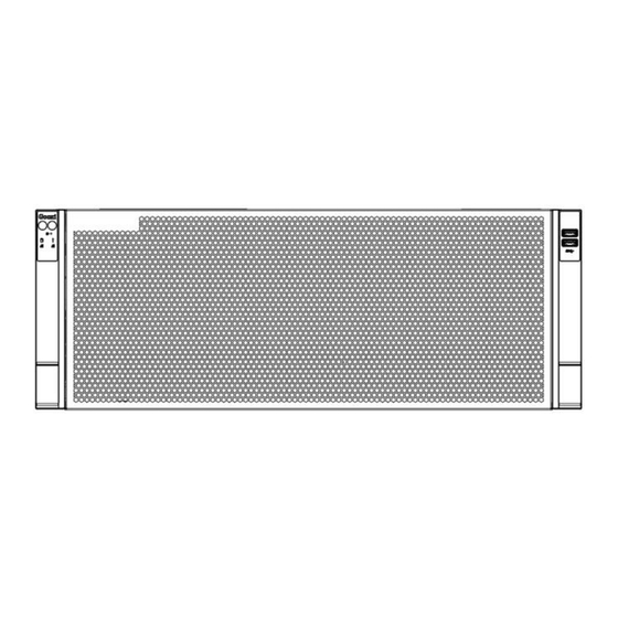
2. Hardware Description 2.1 Front panel 2.1.1 Appearance 11/ 45... -
Page 12: Led And Button
Figure (2-1) Name Name Front panel USB 3.0 interface Table (2-1) 2.1.2 LED and button Figure (2-2) LED/button LED/button Power switch button/LED System alarm LED Network port1 connection status UID button/LED Network port2 connection status Reset server button Hard drive LED LED status description Logo LED/button... -
Page 13: Interface
to start the machine. The UID button/LED is used to conveniently locate the server to be operated, and the LED can be turned off or on by manually pressing the UID button or remotely controlling the BMC command. Description of UID LED: UID button/ LED Blue (on/flashing): Indicates that the server is located. - Page 14 Figure (2-3) Name Description USB 3.0 interface For accessing USB devices Table (2-3) 14/ 45...
-
Page 15: Rear Panel
2.2 Rear panel 2.2.1 Appearance Appearance of the rear panel Figure (2-4) Name Name 2.5-inch hard disk module 2.5-inch hard disk module (optional) (optional) PCIE module (optional) 2.5-inch hard disk module expansion bay (optional) 2.5-inch hard disk module/PCIE module expansion bay Power module1 (optional) Power module2... - Page 16 Figure (2-5) Name Name 1/2/9/10 Power module LED Data transmission status LED Network connection status LED BMC reset button UID LED Table (2-5) LED description LED/button Status description Green on: Indicates that the input and output are normal. Yellow on: Indicates that the AC power cord is unplugged or the power module is lost, and only one parallel-connected power module has AC input;...
-
Page 17: Interface
2.2.3 Interface Rear panel interface Figure (2-6) Name Name 1/2/9/10 Power AC interface COM port IPMI management network port USB interface 1Gigabit Ethernet port Table (2-7) Interface description Name Type Description For connecting display terminal, such as a monitor DB15 or KVM. -
Page 18: Processor
COM port Serial communication port Table (2-8) 2.3 Processor Support 1 AMD EPYC 7003/7002/7001 processor The location of the processor is shown in the figure below: Figure (2-7) 2.4 Memory 2.4.1 Memory slot location The motherboard supports 8 DDR4 channels, each channel supports 2DIMMs, and supports a total of 16 DIMM DDR4 memories (when only one memory is inserted, insert the slot on the motherboard whose plastic color is blue first). -
Page 19: Memory Compatibility Information
Figure (2-8) 2.4.2 Memory compatibility information The motherboard supports DDR4 RDIMM/LRDIMM server memory, and the memory frequency supports 2400/2666/2933/3200MHz. Notice: The same server must use the same type of DDR4 memory, and all memory must run at the same speed, and the speed value is the lowest value of the following items: Memory speed supported by specific CPU. -
Page 20: Power Supply
2x2.5 inch hard 2 SAS/ SATA hard drives or 2 drives NVMe hard drives 4x2.5 inch hard 4 SAS/ SATA hard drives or 4 SAS hard drives NVMe hard drives drives need 6 SAS/ SATA hard drives or (4 to be 6 x 2.5-inch hard NVMe hard drives + 2 SATA hard supported by... -
Page 21: Expansion Module
Support 8 fan modules; Support hot swap; Support single fan failure; Support variable fan speed; For fan modules configured on the same server, the fan module models must be the same; The location of the fan is shown in the figure below: ... -
Page 22: Pcie Module
Figure (2-11) The server can be installed up to five 2.5-inch hard disk modules. Figure (2-12) The expansion bays of serial numbers 3 and 5 can be equipped with PCIE modules. 2.8.2 PCIE module PCIE module 2*Slimline x8 to 2*PCIe3.0x8 (1*x16 SLOT+1*x8 SLOT) –... -
Page 23: Pcba
PCIE module PCIE module Figure (2-14) 2.9 PCBA 2.9.1 Motherboard G2SWA-B Motherboard Diagram (2-15) Name Name 23/ 45... -
Page 24: I/O Board
FAN2 4PIN fan interface FAN 3 4PIN fan socket GPU power supply interface (GPU SATA2 (SATA3.0 Ports) POWER5 ~ 8) FAN6 4PIN fan socket Slim line1 interface FAN5 4PIN fan socket Slim line2 interface FAN9 4PIN fan socket Slim line3 interface Rear IO Conn1 interface MINI SAS HD1 (for connection to IO board) -
Page 25: Hard Disk Backplane
IO board diagram (2-16) Name Name Rear IO Conn2 interface IPMI management network port (for connection to motherboard) Rear IO Conn1 interface (for connection to motherboard) UID button COM port USB 3.0 interface 1Gigabit Ethernet port Table (2-11) 2.9.3 Hard disk backplane 2 ×... - Page 26 Figure (2-18) Description Function Used for hard disk LED positioning light and SGPIO signal interface fault LED indication function Note: This server does not support this function For I2C signal interface I2C interface Note: This server does not support this function 3, 5 7PIN SATA interface SATA disk signal cable interface...
-
Page 27: Gpu Card
Figure (2-20) Description Function Power socket 4Pin power socket for power supply Provide PCIe×4 interface to connect CPU and Slimline 4i connector NVMe SSD JATG debugging JTAG debug interface for program and version interface CPLD Table (2-15) 2.10 GPU card The 4U chassis can support 8 double-width GPU cards or 6 triple-width GPU cards (the length of the GPU card should not exceed 320 mm). -
Page 28: Three-Width Gpu Card
8 double-width GPU cards Figure (2-21) 2.10.2 Three-width GPU card 6 triple-width GPU cards can be installed in the chassis: 6 triple-width GPU cards Figure (2-22) 28/ 45... -
Page 29: Installation Instructions
3. Installation Instructions 3.1 Installation of the upper cover of the chassis Steps: Install the rear upper cover of the chassis 1. Align the nails on the upper cover with the opening of the box and place it downwards 2. Rotate the upper cover lock in the direction of the arrow to lock it in place Figure (3-1) Figure (3-2) 29/ 45... -
Page 30: Mounting Accessories
3.2 Mounting accessories 3.2.1 Install CPU Before starting to install the CPU, please read the following guides: Make sure the motherboard supports the CPU. Before installing the CPU, be sure to turn off the computer and unplug the power cord ... -
Page 31: Installing The Heat Sink
Outer cover Figure (3-3) Figure (3-4) Figure (3-5) 3.2.2 Installing the heat sink Before starting to install the heat sink, please read the following guidelines: 31/ 45... -
Page 32: Install Memory
Always turn off the computer and unplug the power cord from the electrical outlet before installing the heat sink to prevent damage to the hardware. Unplug all cables from electrical outlets. Disconnect all communication cables from their ports. ... -
Page 33: Installing Server Rails
Figure (3-7) Figure (3-8) Figure (3-9) 3.2.4 Installing server rails Step 1: Prepare two slide rails and pull out the inner rail 33/ 45... - Page 34 Figure (3-10) Step 2: Fasten the inner rails to the sides of the case Figure (3-11) (The server in the picture is a schematic diagram, the actual object shall prevail) Step 3: Mount the outer rails on the cabinet brackets and secure the screws ...
- Page 35 Figure (3-12) Note: When installing the guide rail, it is necessary to align with the U mark, and fix it with M 5 screws after hearing a snap sound when it is installed in place. Step 4: Align the chassis with the inner rails installed on the outer rails for installation ...
- Page 36 Figure (3-14) Note: During equipment maintenance, it is necessary to loosen the panel screws and pull the chassis lightly. Do not push or pull the chassis at random speed to avoid damage to the equipment. 36/ 45...
-
Page 37: Configuration Instructions
4. Configuration instructions 4.1 Initial configuration 4.1.1 Power on and start Before powering on, it is necessary to ensure that all configurations of the server are installed in accordance with the corresponding specifications and standards, and keep the server turned off but not unplugged from the power supply. And all cables are connected properly, and the power supply voltage is consistent with that of the device. - Page 38 Figure (4-1) AC Loss Control power-on control Status setting, the menu options are: Always off: Power on and start up directly Always on: To power on, you need to press the Power button to turn on P previous: Leave the power state unchanged Log in to the iBMC management interface to perform remote power-on and power-off ...
-
Page 39: Initial Data
Figure (4-2) 4.1.2 Initial data BMC default account: admin BMC default password: admin BMC default address: 192.168.1.100 BIOS Default Password: None 4.1.3 Configure BIOS Press <DEL> or <ESC> key on the keyboard during power-on and start-up to enter the BIOS Setup interface, as shown below: 39/ 45... -
Page 40: Configure Bmc
Figure (4-3) The Main interface contains the basic information of the BIOS system, such as the BIOS version number, CPU model, memory capacity, and the system time can be set. Navigation key description: →←: Select Screen ↑↓: Select Item Enter: Select +/-:... - Page 41 Figure (4-4) Enter the account password to enter the home page, and you can set the BMC IP address on the management interface. On the left side of the interface, switch to "Settings Page"-> "Network Settings"-> "Network IP Settings". As shown below: Figure (4-5) When the server is powered on, make sure that the BMC dedicated management 41/ 45...
- Page 42 network port cable is properly connected. Use another device, make sure it is in the same LAN as the BMC management network, and enter the BMC IP address on the web page. Check the BMC IP address as follows: After the server is powered on, turn it on. Pay attention to the POST process when starting ...
- Page 43 Configure IPV6 support Choose whether to support IPV6, the menu options are: Enabled: support IPV6 (default) Disabled: does not support IPV6 Change from Unspecified to other parameters, save and restart the execution, the option will restore the value of Unspecified, no need to configure BMC IP every time the startup process. When the Configuration Address source option is Unspecified, it will display the network parameter information (IPV4) of the system shared network port, the current IP configuration mode, BMC IP, subnet mask, MAC address, routing IP, routing MAC.
-
Page 44: Appendix
If the above operation does not solve the fault problem, it is recommended to replace the known correct monitor to confirm whether the original monitor is faulty If there are no problems, please contact Gooxi technical team to solve the problem Warning light on the front panel Please confirm the specific alarm information of the alarm LED according ... - Page 45 PING can be enabled by setting static or dynamic. If the WEB interface is invalid, please change to a new version of IE to connect. If the problem is still not resolved, please contact Gooxi technical team to solve it.
Need help?
Do you have a question about the SR4108G4U and is the answer not in the manual?
Questions and answers