
Subscribe to Our Youtube Channel
Related Manuals for Gooxi ASR4105G-D12R


Summary of Contents for Gooxi ASR4105G-D12R
- Page 1 ASR4105G-D12R 4U Rackmount Server User Manual Document version: 01 Release date: 2023/05/18 Shenzhen Gooxi Information security Co., Ltd.
-
Page 2: Statement
Disclaimer Gooxi provides this user manual "as is" and to the extent permitted by law, makes no express or implied warranties or guarantees, including but not limited to merchantability, fitness for a particular purpose, non-infringement of any rights of others, and any warranties or guarantees regarding the use or inability to use this user manual. -
Page 3: Foreword
Foreword This manual is the product technical manual for the AS401 Whitley platform 4U model servers. It primarily provides an introduction and explanation of the product's appearance, structure, hardware installation, and basic configuration. Please note that this manual is intended for reference and research purposes for professional technical personnel. -
Page 4: Table Of Contents
Contents Statement ..........................1 Foreword ..........................2 ......................4 1.1 Product Overview ......................4 1.2 Product Structure ......................5 1.3 Logical Structure ......................5 1.4 Product Specifications ....................7 ......................8 2.1 Front Panel ........................8 2.1.1 Appearance ....................... 8 2.1.2 Indicator lights and buttons ................8 2.1.3 Interface ...................... -
Page 5: Product Overview
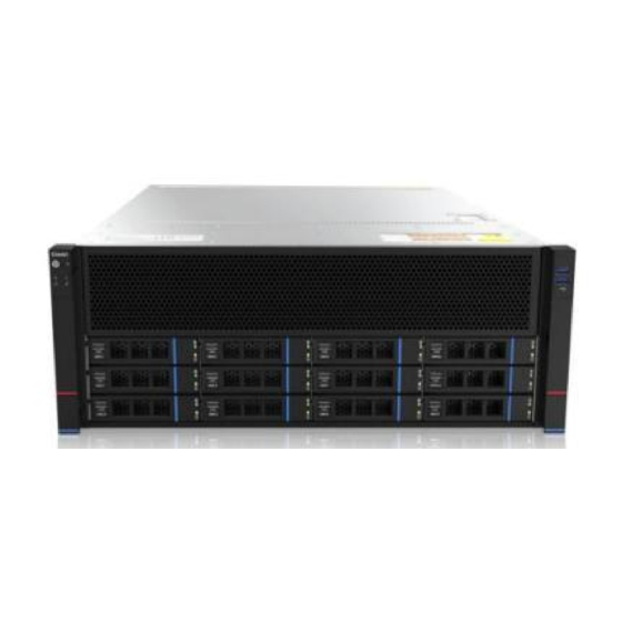
1.1 Product Overview The ASR4105G-D12R dual-socket server is a new-generation 4U rack-mounted server offered by Gooxi to meet the demands of various applications, including the internet, IDC (Internet Data Center), cloud computing, enterprise markets, and telecom services. It is suitable for IT core operations, cloud computing virtualization, high-performance computing, distributed storage, big data processing, enterprise or telecom service applications, and other complex workloads. -
Page 6: Product Structure
Rear View (Figure 1-2) 1.2 Product Structure ASR4105G-D12R server components, as shown in the following image: Structure diagram 1-3 Name Name Front hard drive (optional) Fan bracket Front hard drive module Cover Front panel Power supply enclosure Fan module Rear 2.5-inch hard drive module... - Page 7 DDR4 DIMM0 DDR 4 DIMM0 CH_A CH_A x16 xGMI DDR 4 DIMM0 DDR4 DIMM0 CH_B CH_B CPU0 CPU1 DDR 4 DIMM0 DDR4 DIMM0 x16 xGMI CH_C CH_C DDR 4 DIMM0 DDR4 DIMM0 CH_D CH_D DDR 4 DIMM0 x16 xGMI DDR4 DIMM0 CH_E CH_E DDR 4 DIMM0...
-
Page 8: Product Specifications
1.4 Product Specifications System Model ASR4105G-D12R ASR4105G-D12RE Chassis 4 U rack-mount chassis (695*433*176.5mm) Motherboard G2DERO-B Supports 2 AMD EPYC 7003/7002/7001 series processors 16 DDR4 slots, supports 2133/2400/2666/2933MHz DDR4 RDIMM / LRDIM memory, compatible with a single capacity of 16GB, 32GB, 64GB, 128GB, Memory * the whole machine supports a maximum of 4TB memory capacity. -
Page 9: Front Panel
2.1 Front Panel 2.1.1 Appearance Front view Figure 2-1 Name Name Front switch panel 3. 5-inch hard drive USB 3.0 interface table 2-1 2.1.2 Indicator lights and buttons Figure 2-2 Indicator light /button Indicator light /button Power switch button/indicator System alarm Indicator Reset server button Network port 1 connection... -
Page 10: Interface
Description of the power indicator light: Green (steady on): Indicates that the device has been powered on normally. Green (blinking): Indicates that the device is in standby. Green off: Indicates that the device is not powered on. power indicator Power button description: Short press this button in the power-on state, and the OS will shut down normally. -
Page 11: Rear Panel
Name Type Quantity Description USB interface For accessing USB devices USB 3.0 Table 2-3 2.2 Rear Panel 2.2.1 Appearance Rear panel appearance interface Figure 2-4 power module USB 3.0 interface _ Power module AC port RJ45 Gigabit network port 2.5-inch hard drive module COM port, VGA port (optional) -
Page 12: Indicator Lights And Buttons
You can choose the number of power supplies according to your actual needs, but make sure Power module AC 1 or 2 that the rated power of the power supply is port greater than the rated power of the whole machine rate. -
Page 13: Processor
When configuring 1 processor, it needs to be installed in CPU 0 position. The processors configured in the same server must have the same model. For specific optional system options, please consult Gooxi sales. The position of the processor is as shown in the figure below: ... -
Page 14: Memory
2.4 Memory 2.4.1 Memory slot location The motherboard supports 8 DDR4 channels, each channel supports 1 DIMM, and supports a total of 16 DDR4 slots (When using a single memory module, it is recommended to insert it into the slot indicated by the red box in the diagram below). memory slot location ... -
Page 15: Storage
2.5 Storage 2.5.1 Hard drive configuration Configuration Maximum Number of Maximum Number of Rear Hard Description Front Hard Drives (pcs) Drives (pcs) Supports twelve 3.5" or 1 2x3.5-inch Support 2.5 " SAS/SATA HDD hard drives. 2 *2.5-inch SAS/SATA hard requires the –... -
Page 16: Power Supply
For power modules configured on the same server, the power module models must be the same. For specific optional system options, please consult Gooxi sales. The location of the power supply is shown in the figure below: ... -
Page 17: I/O Expansion
Figure 2-11 2.8 I/O Expansion 2.8.1 PCIe slot location Figure 2-12 The PCIe expansion slots are Slot 1, 2, 3, 4, 5, 6, 7, 8, 9, and 10. 2.8.2 PCIe slot description When CPU1 is not in place, its corresponding PCIe slots are not available. PCIe Slot Subordinate CPU PCIe Standard... -
Page 18: Pcie Expansion Module
Slot 6 CPU 0 PCIe 3.0 or 4.0 x16 slots CPU 1 Slot 7 PCIe 3.0 or 4.0 x16 slots CPU 0 Slot 8 PCIe 3.0 or 4.0 x16 slots CPU 0 Slot 9 PCIe 3.0 or 4.0 x16 slots Slot 10 CPU 0 x16 slots... - Page 19 Motherboard Figure 2-13 Name Chassis fan control 4pin interface (8) ATX 8PIN power connector ATX 8PIN power connector PMBUS ATX 6PIN power connector ATX 6PIN power connector ATX 24PIN power connector Mini SAS HD1/HD2 8643 connector M.2 slot LPC TPM/80 Port 2x10PIN Header FP USB 3.0 *2 Header FP VGA Header SPI TPM Header...
-
Page 20: Hard Drive Backplane
SLOT7 PCIE X16 SLOT6 PCIE X16 SLOT5 PCIE X8 SLOT4 PCIE X8 or X16 SLOT3 PCIE X8 or null SLOT2 PCIE X16 SLOT 1 PCIE X8 Front panel pins DDR4 memory slot SP3 Socket DDR4 memory slot DDR4 memory slot DDR4 memory slot SP3 Socket DDR4 memory slot... - Page 21 used for transmitting 12V and 5V power Temperature-controlled fan socket For 4pin fan interface Used for transmitting 12Gb/s MiniSAS HD High Speed Connector SAS or 6Gb/s SATA signals Table 2-13 2×2.5 rear hard drive backplane TOP surface Figure 2-16 Description Function 1.
-
Page 22: Installation Of The Chassis Top Cover
3.1 Installation of the Chassis Top Cover Step 1: Lift the card slot at the indicated opening, then push it upwards in the direction shown in the diagram. Figure 3-1 3.2 Accessories Installation 3. 2.1 CPU installation Before starting to install the CPU, please read the following guidelines: Make sure the motherboard supports the CPU. - Page 23 Figure (3-2) Figure (3-3) Figure (3-4)
-
Page 24: Heatsink Installation
3.2.2 Heatsink installation. Before starting to install the heatsink, please read the following guidelines: Before installing the heatsink, please be sure to turn off the computer and unplug the power cord from the power outlet to prevent damage to the hardware. Unplug all cables from the power outlet. -
Page 25: Memory Installation
3.2.3 Memory installation 16 memory slots controlled by the motherboard CPU are: CPU0 DIMM A1/B1/C1/D1/E1/F1/G1/H1; CPU1 DIMM A 1/ B 1/ C 1/ D 1/ E 1/ F 1 /G1/H1. Please note that the notch on the memory module should align with the notch on the DIMM slot. Insert each DIMM module vertically to ensure proper installation. -
Page 26: Server Slide Rail Installation
3.2.4 Server slide rail installation Step 1: Prepare two slide rails and pull out the inner rail Figure 3-8 Step 2: Fix the inner rails on both sides of the chassis Figure 3-9 Step 3: Securely fasten the outer rails to the rack brackets using the screws ... - Page 27 Figure 3-11 Note: When you push the chassis forward, you will hear a snap. Only then can you continue to nudge the chassis. Step 5: Secure the screws to complete the installation when the chassis cannot slide forward. Figure 3-12 Note: When performing equipment maintenance, loosen the panel screws, gently pull the chassis, and avoid forcefully pushing or pulling the chassis to prevent equipment damage.
-
Page 28: Initial Configuration
4.1 Initial Configuration 4.1.1 Power on and start Before powering on, ensure that all server configurations are correctly installed according to specifications and standards. The server should be powered off but not disconnected from the power source. Additionally, verify that all cables are properly connected, and the power supply voltage matches the equipment requirements. -
Page 29: Bios Configuration
BMC default password: Gooxi @123. BMC default address: 192.168.100.1 BIOS default password: None Attention to password management: Remember to change your login password!!! 4.1.3 BIOS Configuration During the power-on process, press the <DEL> or <ESC> key on the keyboard to... - Page 30 To find the BMC IP address, follow these steps: After powering on the server and during the startup POST process, pay attention to the logo screen. In the lower-left corner of the logo screen, the IP address should be displayed. After powering on the server, during the startup POST process, press the <DEL>...
- Page 31 DynamicBmcDhcp: BMC is set to run DHCP for dynamic IP allocation. DynamicBmcNonDhcp: BMC is set to run Non-DHCP protocol for dynamic IP allocation. Default value: Unspecified When changed from 'Unspecified' to another parameter and saved before restarting, the option will revert to the 'Unspecified' value. There is no need to configure the BMC IP during each startup process.
- Page 32 Figure 4-5...
- Page 33 Try reseating the RAID card and PCIe adapter to confirm if they are functioning correctly. If the issue persists even after replacing the RAID card with a known working one, restore to factory settings and update the BIOS version. Contact Gooxi technical support for further assistance. IPMI Connection Failure...
- Page 34 Set static or dynamic IP and ensure ping connectivity. If the web interface does not open, try using a newer version of Internet Explorer. If the problem is not resolved, please contact Gooxi technical support for further assistance.
Need help?
Do you have a question about the ASR4105G-D12R and is the answer not in the manual?
Questions and answers