Table of Contents
Advertisement
Available languages
Available languages
Quick Links
Advertisement
Chapters
Table of Contents

Related Manuals for Sartorius CERTOMAT Tplus


Summary of Contents for Sartorius CERTOMAT Tplus
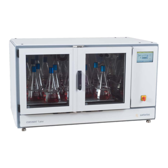
- Page 1 CERTOMAT® Tplus Inkubations-Schüttelschrank Bedienungsanleitung 85032-536-02...
-
Page 2: Besondere Hinweise
Alle Angaben wurden sorgfältig zusammen- Einhaltung der relevanten Sicherheitsmaßregeln gestellt, erfolgen jedoch ohne Gewähr. gewährleisten. Das Personal muss die erforderliche Die Sartorius Stedim Biotech GmbH behält sich Qualifikation für den Anwendungsbereich und den Änderungen in Aufbau und Ausstattung ihrer Umgang mit dem Gerät besitzen. -
Page 3: Table Of Contents
Inhalt Besondere Hinweise EG-Konformitätserklärung Bestimmungsgemäße Verwendung Allgemeine Sicherheitshinweise Leitfaden für diese Anleitung Aufbau und Funktion Hauptfunktion „Main“ Mechanischer Aufbau Funktionselemente des Hauptmenüs „Main“ Ausstattungsmöglichkeiten Starten einer Inkubation aus dem Menü „Main“ ... - Page 4 Hauptfunktion „Alarms“ 10.1 Funktionselemente des Hauptmenüs „Alarms” 10.2 Alarme bestätigen und/oder löschen 10.3 Übersicht zu Prozessalarmen 10.4 Prozessmeldungen 10.5 Kurzbezeichnungen 10.5.1 Prozesswerte 10.5.2 Digitaleingänge 10.5.3 Digitalausgänge ...
-
Page 5: Aufbau Und Funktion
Außenläufermotor und den geräuscharmen, robusten (je nach Ausführung im Lieferzustand; durch den Poly-V-Riemenantrieb. Es sind Schüttelantriebe mit Service der Sartorius AG auch vor Ort auf die unterschiedlichem Hub verfügbar, wobei der Hub alternative Amplitude umstellbar). durch unseren Service vor Ort umstellbar ist. Die •... - Page 6 Teile fehlen oder beschädigt sein, Luftzirkulation vermindert. informieren Sie bitte schnellstmöglich Ihre Vertretung Hierdurch kann der eingebaute Übertemperaturschutz der Sartorius Stedim Biotech GmbH. auslösen und das Gerät schaltet sich ab. Lassen Sie das Gerät einige Zeit akklimatisieren, bevor Sie es wieder im Betrieb nehmen.
- Page 7 Verfügt das Labor nicht über passende Bohrungen an der Oberseite des jeweils unteren Geräteanschlüsse, kann der für Sie zuständige Service Schrankes passen. der Sartorius AG einen geeigneten Gerätestecker montieren. Justieren Sie den Schüttelschrank bzw. die gestapelten Schränke sorgfältig waagrecht. Steht der Schüttelschrank schief, kann der Schüttel- antrieb schnell verschleißen, insbesondere bei schweren...
-
Page 8: Beleuchtungseinrichtung
Schüttelantriebs auf einen anderen Hub darf nur durch qualifizierte und autorisierte Servicetechniker erfolgen. Setzen Sie sich dazu gegebenenfalls mit der zuständigen Service-Vertretung oder direkt mit dem Service-Dienst der Sartorius AG in Verbindung. Abb. 3: Angeschlossene Beleuchtungseinheit 2.3.2 Beleuchtungseinrichtung (Option) •... -
Page 9: Einbau Der Montageleisten (4 Stück)
2.3.4.1 Einbau der Montageleisten (4 Stück) Drücken Sie nun den Haltewinkel zusammen und lassen Sie das untere Ende des Haltewinkels - eine Aussparung Fixieren Sie die erste Montageleiste mit der oberen tiefer - in die Montageleiste einrasten (s. Abb. 8). Schraube an der vorgesehenen Position der Seitenwand (Schraube locker anziehen). -
Page 10: Ausrüstung, Einbau Und Beladung Eines Tablars
Ausrüstung, Einbau und Beladung eines Tablars Die Sartorius Stedim Biotech GmbH bietet fertig bestückte Tablare (mit Haltern für Erlenmeyerkolben bestimmter Größen) oder Tablare ohne Aufbauten. Das Tablar kann bei Auslieferung oder nach Aufstellen des Schüttelschrankes betriebsbereit vorbereitet sein. Wenn damit die von Ihnen benötigten Gefäßhalterungen und Aufbausysteme verfügbar sind,... -
Page 11: Justieren Des Ausgleichsgewichts Für Die
2.4.2 Justieren des Ausgleichsgewichts für die Stecken Sie das Verstellwerkzeug (1) durch die Öffnung vorgesehene Beladung unter der Frontklappe im Gehäuse auf die Achse des Ausgleichsgewichts (2); Im Lieferzustand ist der CERTOMAT® Tplus für eine Drehen Sie das Ausgleichsgewicht mit dem Verstell- Beladung von 10 kg voreingestellt. -
Page 12: Aus- Und Einbau Eines Tablars
2.4.3 Aus- und Einbau eines Tablars Senken Sie das Tablar auf den Schütteltisch ab und schieben Sie es dabei mit den Aussparungen (1a/1b) gegen die hinteren Rändelschrauben (1c/1d) und die Klemme (2a) des Schütteltisches. Beachten Sie das Gewicht des Tablars wenn Sie es bereits mit Schüttelgefäßen beladen haben. -
Page 13: Montage Von Tablaren Und Aufbausystemen
Montage von Tablaren und Aufbausystemen Als fertig bestückte Tablare sind die Tablare Typ E und F erhältlich. Detaillierte Informationen dazu finden Sie 2.5.1 Montage und Beladung fertig bestückter Tablare bei den Bestellinformationen im Anhang. Stellen Sie das Tablar in den CERTOMAT® Tplus und befestigen Sie es wie unter Punkt 2.4.3 (Aus- und Einbau eines Tablars) beschrieben. -
Page 14: Montage Des Universal-Aufbausystems
2.5.3 Montage des Universal-Aufbausystems Stellen Sie die Seitenteile (1) auf das Tablar und schrauben Sie diese fest, vgl. Pos. (1a). Für jedes Universal-Aufbausysteme sind für die Tablare EU sowie Seitenteil sind 4 Schrauben vorgesehen. Montieren Sie FU erhältlich. Im Anhang finden Sie weitere Angaben die Verbindungsstäbe an den Seitenteilen wie in Pos. -
Page 15: Bedienung Des Certomat® Tplus
Shooting) Schutzbrillen und gegebenenfalls Atemschutz tragen. Sie dürfen nur Ausrüstungen verwenden, die die Sartorius Stedim Biotech GmbH für den Einsatz mit dem CERTOMAT® Tplus freigegeben hat. Prüfen Sie die einwandfreie Beschaffenheit aller Teile, insbesondere die Glasgefäße. Verwenden Sie keine beschädigten (Glas)- Teile. -
Page 16: Inbetriebnahme
Inbetriebnahme 3.2.1 Aufstellung und Einstellungen Falls Sie den Aufstellort (z.B. Kühlraum <-> Labor) gewechselt haben, warten Sie, bis sich das Gerät auf Raumtemperatur erwärmt hat, bevor Sie es in Betrieb nehmen. Ansonsten kann Luftfeuchtigkeit im Gerät kondensieren und Funktionsstörungen verursachen. Wenn Sie einen CERTOMAT®... -
Page 17: Systemverhalten Beim Start
3.2.2 Systemverhalten beim Start Bei Rückkehr der Spannung nach einem Netzausfall, der kürzer ist als „Failtime“, arbeitet das System so Nach Einschalten der Steuerungseinheit und weiter: Programmstart, sowie bei Wiederkehr der Spannung nach Stromausfall, befindet sich das Mess- und • Das System zeigt die Fehlermeldung „Power Failure“, Regelsystem in einem definierten Grundzustand: mit Zeitpunkt des Ausfalls. -
Page 18: Grundlagen Der Bedienung Des „Touch Display
Grundlagen der Bedienung des „Touch Display“ Aufteilung des Hauptbildschirms Der Bildschirm „Main" liefert einen grafischen Überblick der Einrichtung des kontrollierten Geräts, mit Symbolen ihrer typischen Anordnung am Schüttler. Kopfzeile, Anzeige des Systemstatus Arbeitsbereich: Anzeige der Funktionselemente*): − Temperaturregler „TEMP“ − Drehzahlregler „SHAKER“ −... -
Page 19: Arbeitsbereich
4.1.2 Arbeitsbereich Der „Arbeitsbereich" zeigt die Funktionselemente und Untermenüs der aktiven Hauptfunktion an: − Vorgewählte Prozesswerte mit ihrem aktuellen Messwert oder Sollwert − Regler, z.B. für Schütteleinheit, usw., mit aktuellen Sollwerten − Im Hauptbildschirm „Main“ werden die aktuellen Istwerte und Istzustände angezeigt. Abb. -
Page 20: Darstellung Der Funktionselemente
Darstellung der Funktionselemente Die Darstellung der Funktionselemente im Arbeitsbereich kennzeichnet ihren aktuellen Status und die vorgesehene Verwendung: Symbol Anzeige Bedeutung, Verwendung Taste mit grauer Unterlinie Messwerterfassung oder Ausgang des Funktionselements ist inaktiv, mit Messwert oder Stellgröße, wie angezeigt Taste mit grüner Unterlinie Messwerterfassung oder Ausgang des Funktionselements ist aktiv, mit Messwert oder Stellgröße, wie angezeigt... -
Page 21: Übersicht Der Hauptfunktionstasten
Übersicht der Hauptfunktionstasten Taste, Symbol Bedeutung, Verwendung Hauptfunktion „Main“ Startbildschirm mit graphischer Übersicht des kontrollierten Gerätes: − Anzeige der Komponenten der aktuellen Konfiguration − Übersicht der Messgrößen und Prozessparameter − Direktzugriff auf wichtige Menüs für Bedieneingaben Hauptfunktion „Controller“ Bedien- und Parametriermenüs für Regler, z.B.: −... -
Page 22: Hauptfunktion „Main
Hauptfunktion „Main“ Starten einer Inkubation aus dem Menü „Main“ Schnellzugriff auf alle Regler (TEMP, SHAKER) und Um eine Inkubation aus dem Menü „Main“ heraus zu Schalter (LIGHT, ILLUM, COOL) erhalten Sie über die starten gehen Sie folgendermaßen vor. Hauptfunktionstaste „Main“ in der Fußzeile. Nach Beispiel: Drücken der Taste erscheint zunächst ein Übersichtsmenü. -
Page 23: Drehzahl Eingeben
5.2.2 Drehzahl eingeben 5.2.4 Photobeleuchtung ein- oder ausschalten • • Taste „SHAKER“ drücken. Taste „ILLUM“ drücken. Es erscheint das Eingabemenü des Drehzahlreglers. Es erschein das Eingabemenü für die Photobeleuchtung (ILLUM). Abb. 24: Eingabe ILLUM „On“/ „Off“” • Photobeleuchtung durch Drücken von „On“ einschalten. -
Page 24: Editieren Einzelner Werte Einer Inkubation Aus Dem Menü „Main
Editieren einzelner Werte einer Inkubation aus dem Menü „Main“ Während der laufenden Inkubation können Sie jederzeit Änderungen einzelner Werte (Temperatur, Drehzahl) oder Zustände (Arbeitsbeleuchtung, Photo- beleuchtung, Kühlung) vornehmen. Ein laufender Inkubationsprozess muss hierzu nicht vorher gestoppt werden. Eine Drehzahl-Eingabe von „0“ /min. -
Page 25: Hauptfunktion „Controller
Hauptfunktion „Controller“ Zugriff auf die Regler Zugriff auf alle Regler erhalten Sie über die Beispiel: Temperaturregler Hauptfunktionstaste „Controller“ in der Fußzeile. 6.2.1 Temperatur-Sollwert eingeben Nach Drücken der Taste erscheint zunächst ein Übersichtsmenü, das die verfügbaren Regler zeigt. • Taste „TEMP“ drücken. Die Reglerbedienbilder öffnen Sie dann durch Drücken Es erscheint das Eingabemenü... -
Page 26: Alarmgrenzen Einstellen
6.2.2 Alarmgrenzen einstellen. • Nach Eingabe der Alarmgrenzen den Alarm durch Drücken der Taste „Alarm“ (Abb. 29, Pos. 5) aktivieren. • Taste „Alarm Param“ drücken. Anzeige zeigt „Alarm enabled“. Es erschein das Eingabemenü „Alarm TEMP“. Zusätzlich werden die Alarmgrenzen durch rote Dreiecke (Abb. -
Page 27: Hauptfunktion „Batches
Hauptfunktion „Batches“ Beispiel für die Erstellung eines Programmes • Insgesamt können 20 verschiedene Programme im Gerät abgespeichert werden. Jedes Programm wiederum besteht aus einem „Pre-Step“ und vier weiteren Steps, die nacheinander abgearbeitet werden. Für jeden Step können die Werte für Kühlung, Photobeleuchtung (ILLUM), Drehzahl und Temperatur unabhängig voneinander eingestellt werden. - Page 28 Beispiel: Am Montagmorgen um 9:00 Uhr sollen Kulturen zur Verfügung stehen. Das Programm (Step1...Step4) zur Herstellung dieser Kulturen benötigt insgesamt 38 h. Somit müsste das Programm ohne Nutzung des „Pre- Step“ am Samstag um 19:00 Uhr manuell gestartet werden. Der „Pre-Step“ erlaubt es, den Startzeitpunkt beliebig zu halten und den Ansatz bis zum Programmbeginn unter gewünschten Bedingungen zu halten.
-
Page 29: Programmdaten Eingeben
Programmdaten eingeben Schritt Taste, Symbol, Anzeige Eingabe Hauptmenü „Batches“ Taste „Batches“ drücken. aufrufen Programm auswählen Taste „Program“ drücken. Programm-Nr. über Programm-Nr. über Bildschirm-Zahlenblock Bildschirm-Zahlenblock eingeben und mit Taste „ok“ bestätigen. eingeben und bestätigen. - Page 30 Schritt Taste, Symbol, Anzeige Eingabe Modus wählen Taste „Mode“ drücken. Programmdaten Taste „Modify“ drücken. eingeben Pre-Step definieren Drehzahl während des Taste „Value“ in Zeile / Spalte „Pre-Step“ „SHAKER“ Pre-Step eingeben drücken. Drehzahl über Bildschirm- Drehzahl über Bildschirm-Zahlenblock eingeben. Zahlenblock eingeben. und mit Taste „ok“...
- Page 31 Schritt Taste, Symbol, Anzeige Eingabe Temperatur während des Taste „Value“ in Zeile / Spalte „Pre-Step“ „TEMP“ Pre-Step eingeben drücken. Temperatur über Temperatur über Bildschirm-Zahlenblock eingeben Bildschirm-Zahlenblock und mit Taste „ok“ bestätigen. eingeben. Alarmmeldung ein- oder Taste „Alarm“ drücken für gewünschten Status. ausschalten deaktiviert aktiviert...
- Page 32 Schritt Taste, Symbol, Anzeige Eingabe Step 1 definieren Laufzeit des Step 1 Taste „Value“ in Zeile / Spalte „Step 1“ „Duration“ eingeben. drücken. Laufzeit [hh:mm] über Laufzeit [hh:mm] über Bildschirm-Zahlenblock Bildschirm-Zahlenblock eingeben und mit Taste „ok“ bestätigen. eingeben. Eingabe der Zeitdauer grundsätzlich in Stunden und Minuten [hh:mm]. Laufzeiten größer 24 h werden nach Eingabe automatisch in Tage, Stunden und Minuten umgerechnet.
-
Page 33: Startzeit Eines Programmes Festlegen
Startzeit eines Programmes festlegen 7.4.1 Programm sofort starten Schritt Taste, Symbol, Anzeige Eingabe Hauptmenü „Batches“ Taste „Batches“ drücken. aufrufen. Modus wählen. Taste „Mode“ drücken. Programm starten. Taste „Start“ drücken. Anzahl der Zyklen Taste „Cycles“ drücken. eingeben. Anzahl der Zyklen über Anzahl der Zyklen über Bildschirm-Zahlenblock Bildschirm-Zahlenblock eingeben und mit Taste „ok“... -
Page 34: Programm Zu Vorgegebenem Zeitpunkt Starten
Programm starten. Taste „Start“ drücken. • Der Prozess startet sofort. 7.4.2 Programm zu vorgegebenem Zeitpunkt starten Schritt Taste, Symbol, Anzeige Eingabe Hauptmenü „Batches“ Taste „Batches“ drücken. aufrufen. Modus wählen. Taste „Mode“ drücken. - Page 35 Menü „Start at time“ Taste „Start at time“ drücken. aufrufen. Startzeit eingeben. Taste „Time“ drücken. Startzeit in Stunden, Startzeit in Stunden, Minuten, Sekunden Minuten, Sekunden [hh:mm:ss] über Bildschirm-Zahlenblock eingeben [hh:mm:ss] über und mit Taste „ok“ bestätigen. Bildschirm-Zahlenblock eingeben. Startdatum eingeben. Taste „Date“...
- Page 36 Anzahl der Zyklen Taste „Cycles“ drücken. eingeben. Anzahl der Zyklen über Anzahl der Zyklen über Bildschirm-Zahlenblock Bildschirm-Zahlenblock eingeben und mit Taste „ok“ bestätigen. eingeben. Programm starten. Taste „Start“ drücken. • Der Prozess startet zum vorgegebenen Zeitpunkt. Bis dahin werden die Bedingungen aus dem „Pre-Step“ ausgeführt.
-
Page 37: Programm Stoppen/ Abbrechen
Programm stoppen/ abbrechen Um ein laufendes Programm zu stoppen oder abzubrechen gehen Sie folgendermaßen vor: Schritt Taste, Symbol, Anzeige Eingabe Hauptmenü „Batches“ Taste „Batches“ drücken. aufrufen. Modus wählen. Taste „Mode“ drücken. Programm stoppen. Taste „Stop“ drücken. Es erfolgt nur ein Programmstopp/ -abbruch. Alle zum Zeitpunkt des Programmstopps/ -abbruchs aktiven Prozesswerte/ -zustände (Temperatur, Drehzahl, Photobeleuchtung und Kühlung bleiben aktiv). -
Page 38: Programm Editieren
Programm editieren Um ein gespeichertes Programm zu editieren gehen Sie folgendermaßen vor: Schritt Taste, Symbol, Anzeige Eingabe Hauptmenü „Batches“ Taste „Batches“ drücken. aufrufen. Zu editierendes Programm Taste „Program“ drücken. wählen. Programm-Nr. über Programm-Nr. über Bildschirm-Zahlenblock Bildschirm-Zahlenblock eingeben und mit Taste „ok“ bestätigen. eingeben und bestätigen. - Page 39 • Werte entsprechend den Erfordernissen anpassen. − Werte editieren wie in Kap. 7.3 „Programmdaten eingeben“ beschrieben. Menü „Batch Parameters“ Taste „Schließen“ drücken. verlassen.
-
Page 40: Hauptfunktion „Settings
Hauptfunktion „Settings“ Funktionselemente des Hauptmenüs „Settings” Die Hauptfunktion Systemeinstellungen „Settings“ Taste, Symbol Bedeutung, Verwendung erlaubt Eingriffe in die Systemkonfiguration. Die Systemeinstellungen („System Aus Einstellungen, die für ein bestimmtes Endgerät Parameters“) erlauben allgemeine unzulässig oder ungeeignet sind, können Fehlfunktionen Einstellungen am DCU System. mit unvorhersehbaren Auswirkungen auf den sicheren Betrieb resultieren. -
Page 41: Bedienmenüs Und Eingabefenster
Bedienmenüs und Eingabefenster 8.3.1 „System Parameters” Nach Drücken der Taste „System Parameters“ und anschließender Eingabe des Standard Passwortes können folgende Einstellungen vorgenommen werden: Feld Wert Funktion hh:mm:ss Eingabe der aktuellen Time Uhrzeit, in „Stunde:Minute:Sekunde“ yyyy-mm-dd Eingabe aktuelles Datum, Date Format „Jahr-Monat-Tag“ hh:mm:ss Eingabe der Netzausfall- Failtime... -
Page 42: Funktion „Remote
Funktion „Remote“ Hauptfunktion „Alarms“ Durch Drücken der Taste „Remote“ wird der Remote- Bei Auftreten eines Alarms erscheint ein betrieb aktiviert bzw. deaktiviert. Meldungsfenster im aktuellen Display, mit Angaben zu Datum, Uhrzeit und Art des aufgetretenen Fehlers. In der Fußzeile wechselt die Farbe der Alarmglocke von „weiß“... -
Page 43: Alarme Bestätigen Und/Oder Löschen
Wie Sie auf Alarme und sonstige Meldungen reagieren können, hängt von deren Art und Ursache ab. Die folgenden Tabellen geben einen Überblick. Bei Fragen zu Alarmen und geeigneten Maßnahmen zur Abhilfe wenden Sie sich an Sartorius Stedim Biotech GmbH. 10.3 Übersicht zu Prozessalarmen Text aus Alarmzeile... -
Page 44: Kurzbezeichnungen
10.5 Kurzbezeichnungen 10.5.3 Digitalausgänge Alle Bezeichnungen der Funktionselemente in den Abkürzung (TAG) Bedeutung, ggf. Maßnahme Bedienmenüs hängen ab von der Konfiguration des DCU-Systems. Standard-Konfigurationen verwenden HEAT Statussignal der Heizung, die folgenden Bezeichnungen: „Heizen” in Betrieb TMPON Heizung eingeschaltet 10.5.1 Prozesswerte SHAON Schüttler eingeschaltet Abkürzung (TAG) Bedeutung... -
Page 45: Anhang
Anhang 11.2.2 Sammelalarm 11.1 Betrieb mit dem eingebauten Kühlaggregat Über die 15-polige Sub-D-Buchse „ANALOG OUT“ werden auf PIN 7/8/15 zwei potentialfreie Kontakte • Bei einem Schüttelschrank mit integriertem zur Verfügung gestellt, mit dem Alarmsituationen Kühlaggregat muss keine Vorsorge für Kondensat- extern gemeldet werden können. -
Page 46: Maßnahmen Bei Betriebsstörungen (Trouble-Shooting)
Formblatt „Function bug handling“ (auf Anfrage erhältlich) die Möglichkeit, das Problem zu Um den Antriebsriemen zu überprüfen, nehmen Sie beschreiben. Damit kann die Sartorius Stedim Biotech das Tablar und den Schütteltisch ab. Lösen Sie dazu die GmbH dem Anwender meist kurzfristig eine 4 Schrauben in der Mitte des Schütteltisches. -
Page 47: Wartungshinweise
Ersatz defekter Leuchtstoffröhren und Geräte- sicherungen. Bei anderen Störungen benachrichtigen Entfernen Sie zerbrochene Glaskolben, verschüttete Sie den für Sie zuständigen Service der Sartorius AG. Flüssigkeiten und Fremdkörper immer schnellstmöglich. Sie sollten Verschmutzungen nicht antrocknen lassen. Schalten Sie die Beleuchtungseinheit aus und trennen Sie das Gerät von der Stromversorgung. -
Page 48: Gewährleistung Und Kundendienst
Sartorius AG repariert werden oder durch autorisiertes zugänglich. Dieses wird nur dem autorisierten Service Servicepersonal vor Ort. Im Fall eines Defektes zur Verfügung gestellt. informieren Sie bitte Ihre Vertretung der Sartorius AG oder direkt Bei Anwahl passwortgeschützter Funktionen erscheint automatisch ein Tastenfeld mit der Aufforderung das Sartorius AG Password einzugeben. -
Page 49: Technische Daten, Bestellinformationen
Schrank aus Stahlblech mit säurefester Lackierung; Innenauskleidung aus Edelstahl Tablare Typ E/EU : (420 x 420 mm) ; Typ F/FU : (800 x 420 mm) Beladung abhängig von Tablar und montierten Aufbausystemen des Sartorius Stedim Biotech GmbH Zubehörprogramms 12.1.2 Elektrischer Anschluss Anschluss Schuko-Steckdose Netzspannung 230 V (±5 %) / 50 Hz oder 115 V (±5 %) / 60 Hz... -
Page 50: Bestelldaten
12.2 Bestelldaten 12.2.1 Schüttlerkonfigurationen Art.-Nr. Bestellinformationen, besondere Merkmale Inkubations-Schüttler CERTOMAT® Tplus / 25 mm Ausführung 230 V / 50 Hz 8865809 Heizversion (UH) 8865906 Heiz- und Kühlversion (UHK) Inkubations-Schüttler CERTOMAT® Tplus / 50 mm Ausführung 230 V / 50 Hz 8865825 Heizversion (UH) 8865922... -
Page 51: Zubehör
12.2.3 Zubehör Art.-Nr. Bestellinformationen, besondere Merkmale Festbestückte Tablare (mit Klammern f. Erlenmeyerkolben) Tablar E 420 x 420 mm – Halteklammern aus Edelstahl 8853533 Tablar mit 39 Klammern für Erlenmeyerkolben 100 ml 8853568 Tablar mit 20 Klammern für Erlenmeyerkolben 250 ml 8853584 Tablar mit 14 Klammern für Erlenmeyerkolben 500 ml 8853606... - Page 52 Art.-Nr. Bestellinformationen, besondere Merkmale Reagenzglasgestelle Abb. 39: Reagenzglasgestell 8853134 Reagenzglasgestell für 64 Gläser Ø 14 mm 8853142 Reagenzglasgestell für 42 Gläser Ø 16 mm 8853150 Reagenzglasgestell für 36 Gläser Ø 18 mm 8853169 Reagenzglasgestell für 33 Gläser Ø 20 mm 8853185 Reagenzglasgestell für 18 Gläser Ø...
- Page 53 Art.-Nr. Bestellinformationen, besondere Merkmale 8854572 Halteklammern für Erlenmeyer-Kolben 500 ml Bestückungskapazität des Tablars bei Tablar Typ EU - max. 12 Stück bei Tablar Typ FU - max. 26 Stück 8854599 Halteklammern für Erlenmeyer-Kolben 1.000 ml Bestückungskapazität des Tablars bei Tablar Typ EU - max. 8 Stück bei Tablar Typ FU - max.
- Page 54 Art.-Nr. Bestellinformationen, besondere Merkmale Halteklammern aus Kunststoff für Erlenmeyer-Kolben (zur wahlweisen Bestückung der Universal - Tablare) 8854700 Halteklammern aus Kunststoff für Erlenmeyerkolben 100 ml Bestückungskapazität der Universal – Tablare bei Tablar Typ EU - max. 20 Stück bei Tablar Typ FU - max. 58 Stück 8854711 Halteklammer aus Kunststoff für Erlenmeyerkolben 250 ml Bestückungskapazität der Universal-Tablare...
- Page 55 Art.-Nr. Bestellinformationen, besondere Merkmale Schüttelkolben (Kulturkolben Erlenmeyer-Form, mit Schikanen) Abb. 41: Schüttelkolben mit Schikanen in der Wandung Schüttelkolben aus DURAN-Glas, Erlenmeyer-Form; gerader Hals für Metallkappen, Hals, außen Ø = 38 mm; Ausführung für Verschluss-Stopfen Kolbenwandung mit 3 Schikanen (∠ 120°) 8861005 Ausführung 300 ml, Ø...
- Page 56 Art.-Nr. Bestellinformationen, besondere Merkmale Universal-Spannleiste Typ U Abb. 43: Universal-Spannleiste 8854254 Typ U für Basiselemente B-2 und B-3 Abb. 44: Aufbausystem mit 3 Universal-Spannleisten Aufbausatz für Scheidetrichter Typ S Abb. 45: Aufbausatz für Scheidetrichter 8854262 Typ S-1 für 5 Stück Scheidetrichter 50 oder 100 ml; mit Klammern, Rückhaltefedern und 1 Universalspannleiste U-2 8854270 Typ S-2 für 3 Stück Scheidetrichter 250, 500 oder 1000 ml;...
-
Page 57: Sicherheitshinweise Für Laborschüttler
12.3 Sicherheitshinweise für Laborschüttler (Sicherheitshinweise für Laborschüttler s. Anlage) 12.4 EG-Konformitätserklärung (EG-Konformitätserklärung s. Anlage) 12.5 Dekontaminationserklärung (Dekontaminationserklärung s. Anlage) 12.6 Entsorgungs- und Reparaturhinweise (Entsorgungs- und Reparaturhinweise s. Anlage 12.7 Maßblatt CERTOMAT® Tplus (Maßblatt/Aufstellplan CERTOMAT® Tplus s. Anlage) 12.8 Prospekt CERTOMAT® Tplus (Informationen zum Zubehör finden Sie anliegend) - Page 58 Genehmigung der Sartorius Stedim Biotech GmbH nicht gestattet. Alle Rechte nach dem Gesetz über das Urheberrecht bleiben der Sartorius Stedim Biotech GmbH vorbehalten. Die in dieser Anleitung enthaltenen Angaben und Abbildungen entsprechen dem unten angegebenen Stand.
- Page 59 Sicherheitshinweise Laborschüttler und Inkubations-Schüttelschränke 85030-520-67...
- Page 60 Inhalt Einführung Transport und Installation Transport der Geräte Anforderungen an den Aufstellort Betriebshinweise Umgang mit Medien Inbetriebnahme und Normalbetrieb Reinigung, Wartung und Service ...
- Page 61 Sie über Vorsichtsmaßregeln für CERTOMAT ® Die Schüttler und besonders die Inkubations- Laborschüttler und Inkubationsschüttelschränke aus schüttelschränke sind sehr schwer. Verwenden Sie daher dem Produktprogramm der Sartorius Stedim Biotech für den Transport zum Aufstellort und bei GmbH, insbesondere für: Standortwechsel nur dazu geeignete Werkzeuge, Transport- und Hebemittel.
- Page 62 Handschuhe, Schutzbrillen und gegebenenfalls Atemschutz. Inbetriebnahme und Normalbetrieb Verwenden Sie ausschließlich Geräte und Zubehörteile, welche die Sartorius Stedim Biotech GmbH für den Einsatz mit dem Schüttler freigegeben hat. Überprüfen Sie die einwandfreie Beschaffenheit aller Teile, insbesondere bei Glasgefäßen. Beschädigte Teile dürfen nicht verwendet werden.
- Page 63 Rücksenden von defekten Geräten Reinigung, Wartung und Service Defekte Geräte oder Komponenten können Sie an die Regelmäßige Reinigung und Wartung erhält die Geräte zuständige Sartorius AG-Vertretung oder an die funktionsfähig und betriebssicher. Sartorius AG einsenden. Beachten Sie die für den Anwendungsbereich Die Geräte müssen gereinigt, hygienisch einwandfrei...
- Page 64 Sartorius Stedim Biotech GmbH August-Spindler-Straße 11 37079 Göttingen Telefon +49.551.308.3118 Fax +49.551.308.3918 www.sartorius-stedim.com Copyright by Sartorius Stedim Biotech GmbH, Göttingen, Deutschland. Nachdruck oder Übersetzung, auch auszugsweise, ist ohne schriftliche Genehmigung der Sartorius Stedim Biotech GmbH nicht gestattet. Alle Rechte nach dem Gesetz über das Urheberrecht bleiben der...
- Page 67 Seite F-13-01 1 / 4 Rückware Version Gültig ab 01.01.2008 Erklärung über die Dekontaminierung und Reinigung von Geräten und Komponenten Sofern Sie die Geräte oder Komponenten zurücksenden, teilen Sie uns bitte auf Seite 2 dieses Formblattes mit, was Sie zu beanstanden haben und welche Arbeiten ausgeführt werden sollen.
- Page 68 Seite F-13-01 2 / 4 Rückware Version Gültig ab 01.01.2008 C. Rechtsverbindliche Erklärung Hiermit versichere ich/wir, daß die Angaben in diesem Formular korrekt und vollständig sind. Die Geräte und Komponenten wurden entsprechend den gesetzlichen Bestimmungen sachgemäß dekontaminiert und gereinigt. Von den Geräten gehen keinerlei chemische, biologische oder radioaktive Risiken aus, die eine Gefährdung für die Sicherheit oder die Gesundheit betroffener Personen darstellt.
- Page 69 Sartorius AG Bitte verpacken Sie das Gerät sachgemäß und senden Sie es Servicezentrum Nord frei Empfänger an Ihren zuständigen lokalen Service oder Weender Landstraße 94-108 direkt an Sartorius AG Servicezentrum Nord 37075 Göttingen Telefon +49.551.308.3729 / 3740 / 3741 Fax +49.551.308.3730...
- Page 70 Seite F-13-01 4 / 4 Rückware Version Gültig ab 01.01.2008 Sartorius Stedim Biotech GmbH August-Spindler-Straße 11 37079 Göttingen, Germany Telefon +49.551.308.0 Fax +49.551.308.3289 www.sartorius-stedim.com Copyright by Sartorius Stedim Biotech GmbH, Göttingen, Deutschland. Nachdruck oder Übersetzung, auch auszugsweise, ist ohne schriftliche Genehmigung der Sartorius Stedim Biotech GmbH nicht gestattet.
- Page 71 Mitgliedsstaaten, elektrische und elektronische Geräte vom unsortierten Sied- lungsabfall getrennt zu erfassen, um sie anschließend wiederzuverwerten. In Deutschland und einigen anderen Ländern führt die Sartorius AG die Rücknahme und gesetzeskonforme Entsorgung ihrer elektrischen und elektronischer Produkte selbst durch. Diese Produkte dürfen nicht – auch nicht von Kleingewerbetreibenden –...
- Page 75 CERTOMAT® Tplus Incubation Shaking Cabinet Operating Manual 85032-536-02...
- Page 76 Sartorius Stedim Biotech GmbH reserves • Please take special care regarding the operating the right to modify the equipment and to change this information.
- Page 77 Contents Introductionary Note EG Statement of Conformity Intended Use General Safety Notes Guide through this Manual Design and Function "Main" Function Design and Construction Features Functional Elements of the "Main" Menu Available Equipment and Accessories Starting an Incubation from the "Main"...
- Page 78 "Remote Function" Functional Elements of the "Remote” Function Main "Alarms" Function 10.1 Functional Elements of the Main "Alarms" Menu 10.2 Confirming and/or deleting Alarms 10.3 Overview of Process Alarms ...
-
Page 79: Design And Function
The mounting of the tray insert is described in chapter 2.3.4 Installation of the Grid for Petri Dishes (optionally). Trays of modified design for actual locking; rebuilding of old trays for this locking on request. Please contact the Sartorius customer service. -
Page 80: Delivery And Installation
Sartorius Stedim Biotech GmbH representative as soon If the machine is operated continuously for a long as possible. period in conditions of relatively high humidity, ice can form on the vaporiser. -
Page 81: Installation And Laboratory Connection
• If the plug at the power supply cable does not fit to your sockets, the service technician of Sartorius AG can Carefully level the incubation shaker or the stacked attach a suitable plug. units. -
Page 82: Configuration Of The Certomat® Tplus And Optional Equipment
Rebuilding to a different orbit must only be done by authorized and qualified service personnel. Please contact your service representative or the service department of Sartorius AG, if necessary. Fig. 3: Affiliated illumination unit 2.3.2 Illumination Unit (option) -
Page 83: Installation Of The Mounting Rails (4 Pieces)
2.3.4.1 Installation of the Mounting Rails (4 pieces) Now press the angle bracket in such a way that the lower end of it snaps in the mounting rail – one recess Attach the first mounting rail with the upper screw in notch under it (see figure 8). -
Page 84: Equipment, Mounting And Loading Of A Tray
Equipment, Mounting and Loading of a Tray Sartorius Stedim Biotech GmbH offers trays for the CERTOMAT® Tplus fixed with sets of universal clamps for Erlenmeyer flasks of different sizes, or trays without assemblies. On delivery or after the first set- up of the CERTOMAT®... -
Page 85: Adjustment Of The Counter Weight To The Intended Load
2.4.2 Adjustment of the Counter Weight to the Intended Put the variable tool (1) through the opening under the Load front flap in the housing and guide it on the axis of the counter weight (2); Upon delivery the CERTOMAT® Tplus is preadjusted for Turn the counter weight with the variable tool in the a load of 10 kg. -
Page 86: Mounting And Dismounting A Tray
2.4.3 Mounting and Dismounting a Tray Place the tray onto the shaking table. Push it with the indents (1a/1b) against the rear knurled screws (1c/1d) and the clamp (2a) of the shaking table. Please mind the weight of the tray if you have already loaded it with shaking containers. -
Page 87: Mounting Of Trays And Mounting Sets
Mounting of Trays and Mounting Sets The trays type E and F are available as completely equipped trays. Detailed information you will find in 2.5.1 Assembly and Loading of Finally Equipped Sets of the “Ordering Information“ in the supplement. Trays Place the tray in the CERTOMAT®... -
Page 88: Mounting Of The Universal Mounting System
2.5.3 Mounting of the Universal Mounting System Place the side parts (1) onto the tray and screw them onto the tray with the mounting screws as shown at The universal mounting set is available for the trays of pos. (1a). For each side part 4 screws are supplied to size EU and FU. -
Page 89: Operating Information
Maintenance and Trouble-Shooting. Only equipment and accessories must be used which Sartorius Stedim Biotech GmbH has released for the Tplus. Before starting operation all parts should be checked for damages, especially the glass parts. You must not use any damaged or defective equipment. -
Page 90: Equipment, Mounting And Loading Of A Tray
Equipment, Mounting and Loading of a Tray 3.2.1 Equipping the Tray If you have changed the mounting place (e. g. cooling room <-> laboratory) please wait until the device has warmed up to room temperature before you start it. Otherwise the air humidity may condensate in the device leading to functional disturbances. -
Page 91: System Behaviour At The Start
3.2.2 System behaviour at the Start When the voltage returns after a power failure that was shorter than "Failtime", the system continues to After switching on the control unit and program start work as it was: as well as following the return of the power after a power failure the measuring and regulating system is •... -
Page 92: Basics Of The Operation Of The "Touch Display
Basics of the Operation of the "Touch Display" Layout of the main screen The "Main" screen provides a graphic overview of the installation of the controlled device where symbols indicate the typical arrangement in the shaker. Header, display of the system status Working range: display of the functional elements*): −... -
Page 93: Working Area
4.1.2 Working Area The "working area" shows the functional elements and submenus of the active main function: − Preselected process values with their current measured value or set value − Controllers, e.g. for shaking unit, etc., with current set values −... -
Page 94: Display Of The Functional Elements
Display of the Functional Elements The display of the functional elements in the working area indicates their current status and intended use: Symbol Display Meaning, Use Key with grey underline Measured value recording or output of the functional element is inactive, with measured value or control variable as shown Key with green underline Measured value recording or output of the... -
Page 95: Overview Of The Main Function Keys
Overview of the Main Function Keys Key, Symbol Meaning, Use "Main" function Start screen with graphical overview of the controlled device: − Display of the components of the current configuration − Overview of the measured variables and process parameters − Direct access to important menus for operating inputs Main "Controller"... -
Page 96: Main" Function
"Main" Function Starting an Incubation from the "Main" Menu Fast access to all controllers (TEMP, SHAKER) and In order to start an incubation from the "Main" menu, switches (LIGHT, ILLUM, COOL) is obtained via the proceed as follows. "Main" function key in the footer. After pressing the Beispiel: key an overview menu appears first. -
Page 97: Entering The Speed
5.2.2 Entering the Speed 5.2.4 Switching the Photo Illumination on or off • • Press the "SHAKER" key. Press the "ILLUM" key. The input menu of the speed controller appears. The input menu for the photo illumination (ILLUM) appears. Fig. 24: Entry for ILLUM "On"/ "Off" •... -
Page 98: Editing Individual Values Of An Incubation From The "Main" Menu
Editing individual Values of an Incubation from the "Main" Menu While the incubation is running, changes can be made to individual values (temperature, speed) or states (working light, photo illumination, cooling) at any time. A running incubation process does not have to be stopped beforehand in order to do so. -
Page 99: Main "Controller" Function
Main "Controller" Function Access to the Controller Access to all controllers is gained via the main Example: Temperature Controller "Controller" function key in the footer. 6.2.1 Entering the Set Temperature Value After pressing the key an overview menu appears first that shows the available controllers. -
Page 100: Setting The Alarm Limits
6.2.2 Setting the Alarm Limits • After entering the alarm limits activate the alarm by pressing the "Alarm" key (Fig. 29, Pos. 5). • Press the "Alarm Param" key. Display shows "Alarm enabled". The "Alarm TEMP" input menu appears. In addition the alarm limits are indicated by red triangles (Fig. -
Page 101: Main "Batches" Function
Main "Batches" Function Example of Creating a Program • A total of 20 different programs can be stored in the device. Each program consists in turn of a "Pre-step" and four further steps that are worked through one after the other. For each step the values for cooling, photo illumination (ILLUM), speed and temperature can be set independently of one another. - Page 102 Example: On Monday morning at 9:00 o’clock any cultures have to be ready. The program (Step 1 ... Step 4) for the production of these cultures needs altogether 36 h. So the program must be started manually without use of the “Pre-step“...
-
Page 103: Entering Program Data
Entering Program Data Step Key, Symbol, Display Input Call up main "Batches" Press the "Batches" key. menu Select program Press the "Program" key. Enter program no. via Enter program no. via screen keypad and screen keypad and confirm. confirm with "ok" key. - Page 104 Step Key, Symbol, Display Input Select mode Press the "Mode" key. Enter program data Press the "Modify" key. Define pre-step Enter speed during the Press the "Value" key in "Pre-Step" line / "SHAKER" pre-step column. Enter speed via screen Enter speed via screen numeric keypad and keypad.
- Page 105 Step Key, Symbol, Display Input Enter temperature during Press "Value" key in "Pre-Step" line / "TEMP" the pre-step column. Enter temperature via Enter temperature via screen keypad and confirm numeric keypad on the with "ok" key. screen. Switch alarm message on or Press "Alarm"...
- Page 106 Step Key, Symbol, Display Input Define step 1 Enter operating time of Press "Value" key in "Step 1" line / "Duration" step 1 column. Enter operating time Enter operating time [hh:mm] via screen keypad [hh:mm] via screen keypad. and confirm with "ok" key. Input of the duration is basically made in hours and minutes [hh:mm].
-
Page 107: Specifying The Start Time Of A Program
Specifying the Start Time of a Program 7.4.1 Starting the Program immediately Step Key, Symbol, Display Input Call up main "Batches" Press "Batches" key. menu. Select mode. Press "Mode" key. Start the program. Press "Start" key. Enter number of cycles. Press "Cycles"... -
Page 108: Starting The Program At A Specified Time
Start the program. Press the "Start" key. • The process starts immediately. 7.4.2 Starting the Program at a specified Time Step Key, Symbol, Display Input Call up main "Batches" Press the "Batches" key. menu. Select mode. Press the "Mode" key. - Page 109 Call up the "Start at time" Press the "Start at time" key. menu. Enter start time. Press the "Time" key. Enter start time in hours, Enter start time in hours, minutes, seconds minutes, seconds [hh:mm:ss] via screen keypad and confirm with [hh:mm:ss] via screen "ok"...
- Page 110 Enter number of cycles Press "Cycles" key. Enter number of cycles via Enter number of cycles via screen keypad and screen keypad. confirm with "ok" key. Start the program. Press the "Start" key. • The process starts at the specified time. The conditions from the "pre-step" are carried out until then.
-
Page 111: Stopping / Cancelling A Program
Stopping / Cancelling a Program To stop or cancel a running program, proceed as follows: Step Key, Symbol, Display Input Call up main "Batches" Press the "Batches" key. menu. Select mode. Press the "Mode" key. Stop program. Press the "Stop" key. Only a program stop/cancellation takes place. -
Page 112: Editing The Program
Editing the Program In order to edit a stored program, proceed as follows: Step Key, Symbol, Display Input Call up main "Batches" Press the "Batches" key. menu. Select program to be Press the "Program" key. edited. Enter program no. via Enter program no. - Page 113 • Adjust values according to requirements. − Edit values as described in section 7.3 "Entering Program Data". Leave "Batch Parameters" Press "Close" key. menu.
-
Page 114: Main "Settings" Function
Main "Settings" Function Functional Elements of the Main "Settings" Menu The main funktion "Settings" enables interventions in Key, Symbol Meaning, Use the system configuration. The system settings ("System Malfunctions with unforeseeable effects on safe Parameters") enable general operation can arise from settings that are not settings on the DCU system. -
Page 115: Operating Menus And Input Window
Operating Menus and Input Window 8.3.1 "System Parameters" After pressing the "System Parameters" key and subsequent entry of the standard password the following settings can be carried out: Field Value Function hh:mm:ss Entry of current time, in Time "hours:minutes:seconds" format yyyy-mm-dd Entry of current date, in Date... -
Page 116: "Remote Function
"Remote Function" Main "Alarms" Function The remote mode is activated or deactivated by If an alarm occurs, a message window appears on the pressing the "Remote" key. current display with details of the date, time and type of error that occurred. The colour of the alarm bell in the footer changes from "white"... -
Page 117: Confirming And/Or Deleting Alarms
How to react to alarms and other messages depends on their type and cause. The following tables give an overview. If you have any queries about alarms and suitable measures for their remedy, please contact Sartorius Stedim Biotech GmbH. 10.3 Overview of Process Alarms Text from alarm line... -
Page 118: Abbreviations
10.5 Abbreviations 10.5.3 Digital Outputs All designations of the functional elements in the Abbreviation Meaning (and measure if operating menus depend on the configuration of the (TAG) necessary) DCU system. Standard configurations use the following designations: HEAT Status signal of the heating, "Heating"... -
Page 119: Appendix
Appendix 11.2.2 Collective Alarm 11.1 Operation of the Internal Cooling Unit Via the 15-pin sub-D "ANALOG OUT" socket two ® potential-free contacts are available on PIN 7/8/15 • If the CERTOMAT Tplus is equipped with the optional which can be used to externally register alarm cooling unit, you need not care for condensate situations. -
Page 120: Maintenance And Trouble-Shooting
This can activate the overheating safety cut-out and Sartorius AG. You will find the telephone number on switch off the machine. the next page. Allow the machine to cool down before turning it on 11.3.2 Malfunctions of the Shaking Drive... -
Page 121: Maintenance
If other malfunctions occur, please contact your After cleaning and disinfection with such agents you service representative of Sartorius AG. should thoroughly dry and ventilate the incubation room. Switch-off the illumination unit and disconnect from its mains supply. -
Page 122: Warranty Regulations And Service
"Manual Operation" level. shaking cabinet CERTOMAT® Tplus. The "Service" submenu of the main "Settings" function Repairs can be carried out by the Sartorius AG service can only be accessed with a special service password. representative or by authorized personnel of a This is only available to authorized service personnel. -
Page 123: Technical Data, Ordering Information
Trays, type/size Type E/EU (420 x 420 mm) ; type F/FU : (800 x 420 mm) Load depending on tray and mounting system of the Sartorius Stedim Biotech GmbH accessory program 12.1.2 Mains Supply Laboratory connector laboratory grounded socket (specific connectors on request) Mains specifications 230 V (±5 %) 50 Hz or 115 V (±5 %) 60 Hz... -
Page 124: Ordering Information
12.2 Ordering Information 12.2.1 Configuration of the Shaking Cabinets Cat.-no. Features and Specifications Incubation shaker CERTOMAT® Tplus / 25 mm Version 230 V / 50 Hz 8865809 Heating version (UH) 8865906 Heating and cooling version (UHK) Incubation shaker CERTOMAT® Tplus / 50 mm Version 230 V / 50 Hz 8865825 Heating version (UH) -
Page 125: Accessories
12.2.3 Accessories Cat.-no. Features and Specifications Trays with fixed clamps (with clamps for Erlenmeyer flasks) Tray E 420 x 420 mm – clamps made of stainless steel 8853533 Tray incl. 39 clamps for Erlenmeyer flasks 100 ml 8853568 Tray incl. 20 clamps for Erlenmeyer flasks 250 ml 8853584 Tray incl. - Page 126 Cat.-no. Features and Specifications Test Tube Racks Fig. 39: Test tube rack 8853134 Test tube rack for 64 test tubes Ø 14 mm 8853142 Test tube rack for 42 test tubes Ø 16 mm 8853150 Test tube rack for 36 test tubes Ø 18 mm 8853169 Test tube rack for 33 test tubes Ø...
- Page 127 Cat.-no. Features and Specifications 8854572 Clamps for Erlenmeyer flasks 500 ml required / possible max. number of clamps for tray type EU - max. 12 pcs. for tray type FU - max. 26 pcs. 8854599 Clamps for Erlenmeyer flasks 1.000 ml required / possible max.
- Page 128 Cat.-no. Features and Specifications Plastic clamps for Erlenmeyer flasks (optional equipment of the universal trays) 8854700 Plastic clamps for Erlenmeyer flasks 100 ml required / possible max. number of clamps for tray type EU - max. 20 pcs. for tray type FU - max. 58 pcs. 8854711 Plastic clamps for Erlenmeyer flasks 250 ml required / possible max.
- Page 129 Cat.-no. Features and Specifications Shaking flask Erlenmeyer type, with baffles for increased turbulence Fig. 41: Shaking flask Erlenmeyer type; with baffles in the concave side-wall section shaking flask made of DURAN ® -glass, Erlenmeyer-type; straight neckpiece for metal caps; neckpiece of Ø = 38 mm or version with cellucotton stoppers flask body with three baffles at Δ...
- Page 130 Cat.-no. Features and Specifications Universal clamping rod type U Fig. 43: Universal clamping rod 8854254 type U for basic elements B-2 and B-3 Fig. 44: Mounting system with universal clamping rods Mounting set for separating funnels type S Fig. 45: Mounting set for separating funnels type S 8854262...
-
Page 131: Safety Instructions Laboratory Shakers And Incubation Shaking Cabinets
12.3 Safety Instructions Laboratory Shakers and Incubation Shaking Cabinets Safety Instructions Laboratory Shakers and Incubation Shaking Cabinets see appendix) 12.4 EG Declaration of Conformity (EG Declaration of Conformity see appendix) 12.5 Declaration of Decontamination (Declaration of Decontamination see appendix) 12.6 Information and Instructions on Disposal and Repairs (Information and Instructions on Disposal and Repairs see appendix) 12.7... - Page 132 Sartorius Stedim Biotech GmbH August-Spindler-Straße 11 37079 Göttingen, Germany Telephon +49.551.308.0 Fax +49.551.308.3289 www.sartorius-stedim.com Copyright by Sartorius Stedim Biotech GmbH, Göttingen, Germany. All rights resserved. No part of this publication may be reprinted or translated in any form or by any means without the prior written permission of Sartorius Stedim Biotech GmbH.
- Page 133 Safety Instructions Laboratory Shakers and Incubation Shaking Cabinets 85030-520-67...
- Page 134 Content Introduction Transport and Installation Transporting Equipment Requirements at the site of installation Operating Instructions Working with Media Initial Startup and Normal Operation Cleaning, Maintenance, and Service ...
- Page 135 The shakers and especially the incubation shaking shakers and incubation shaking cabinets from the cabinets are heavy. Use only suitable transportation and product program of the company Sartorius Stedim lifting tools when moving or setting up units. Biotech GmbH, especially for Make sure clearances are sufficient along the transport •...
- Page 136 Initial Startup and Normal Operation Use only units, equipment, accessories, and spare parts released by the company Sartorius Stedim Biotech GmbH for use with the shaker. Check all components for damage, especially glass components such as jars. Any damaged components must not be used.
- Page 137 Cleaning, Maintenance, and Service Defective units or components can be returned to the Regular cleaning and maintenance ensures the responsible Sartorius AG representative or directly to equipment's functionality and safety. Sartorius AG. Comply with the legal safety regulations applicable to...
- Page 138 Sartorius Stedim Biotech GmbH August-Spindler-Straße 11 37079 Göttingen, Germany Telephone +49.551.308.0 Fax +49.551.308.3289 www.sartorius-stedim.com Copyright by Sartorius Stedim Biotech GmbH, Göttingen, Germany. All rights reserved. No part of this publication may be reprinted or translated in any form or by any means without the prior written permission of Sartorius Stedim Biotech GmbH.
- Page 141 F-13-01 Page 1 / 4 Return of material Version Effective Date 01.01.2008 Declaration about decontamination and cleaning of equipment and components When returning equipment or components, please describe on page 2 of this form the problem(s) or fault(s) you have found. Please also indicate the remedial actions you require.
- Page 142 F-13-01 Page 2 / 4 Return of material Version Effective Date 01.01.2008 C. Legally binding declaration I (we) certify that all information given in this form is correct and complete. The equipment and components have been adequately decontaminated and cleaned according to the legal requirements. No chemical or biological or radioisotopic risks remain that can endanger exposed persons' safety or health.
- Page 143 Notes Sartorius AG Please pack the unit properly and send it freight paid to your Servicezentrum Nord local service supplier or directly to Sartorius AG Servicezentrum Weender Landstraße 94-108 Nord, Germany. 37075 Göttingen, Germany Telephone +49.551.308.3729 / 3740 / 3741...
- Page 144 Sartorius Stedim Biotech GmbH. The status of the information, specifications and illustrations in this manual is indicated by the date given below. Sartorius Stedim Biotech GmbH reserves the right to make changes to the technology, features, specifications, and design of the equipment without notice.
- Page 145 Service Center Weender Landstrasse 94-108 37075 Goettingen, Germany In countries that are not members of the European Economic Area (EEA) or where no Sartorius affiliates, subsidiaries, dealers or distributors are located, please contact your local authorities or a commercial disposal operator.
- Page 149 CERTOMAT® Tplus Agitateur/incubateur forme armoire- Mode d`emploi 85032-536-02...
- Page 150 Avec les déclarations de conformité fournies ou jointes moment précis indiqué par le numéro de révision. à cet appareil, Sartorius Stedim Biotech GmbH déclare la concordance du CERTOMAT ® Tplus avec les directives Toutes les données de ce mode d'emploi ont été...
- Page 151 Remarques concernant la sécurité Précis du mode d'emploi • Les responsables du laboratoire ou les personnes Ce mode d'emploi est bâti selon le schéma suivant. De responsables de l'utilisation des appareils doivent cette manière, vous pouvez accéder de manière ciblée prévenir le personnel des dangers lors de l'exploitation aux informations importantes en fonction de vos du CERTOMAT ®...
- Page 152 Sommaire Remarques préalables Déclaration de conformité EG Utilisation conforme aux prescriptions Remarques concernant la sécurité Précis de ce mode d’emploi Structure et Fonctionnement Fonction principale „Main“ (Principal) Construction mécanique Eléments fonctionnels du menu principal „Main“ ...
- Page 153 59 12.4 Déclaration de conformité EG 12.5 Déclaration de décontamination (pour renvoi d’appareils) 12.6 Instructions d’élimination des déchets et de réparation 12.7 Plan joint CERTOMAT Tplus 12.8 Accessoires ...
-
Page 154: Structure Et Fonctionnement
à courroie poly V version à l'état de livraison; réglable par le service solide à faible émission de bruits. Des entraînements après-vente de Sartorius AG sur place sur l'amplitude). d'agitation aux courses différentes sont disponibles, la •... -
Page 155: Pose Et Mise En Service
Le givrage de l'évaporateur permet de réduire la succursale de Sartorius Stedim Biotech GmbH. circulation d'air. Ici, la protection de surtempérature montée peut être déclenchée et l'appareil se déconnecte. -
Page 156: Pose Et Raccordement À Effectuer Par Le Laboratoire
Veillez à observer le poids des armoires. d'appareils correspondants, le service habilité de N’utilisez que des outils de levage ou outils auxiliaires Sartorius AG doit monter une fiche d'appareil appropriés. Les goupilles de centrage doivent appropriée. concorder sans coincer dans les alésages situés sur le côté... -
Page 157: Equipement Du Certomat® Tplus Et Raccordement Des Options D'équipement
Fig. 3: Unité d’éclairage raccordée maintenance de la société Sartorius AG. 2.3.2 Dispositif d’éclairage (option) • nsérez le dispositif d'éclairage dans les rails de guidage prévus à cet effet. Desserrez préalablement les 4 vis de fixation des rails d'insertion. -
Page 158: Montage Des Barrettes De Montage
2.3.4.1 Montage des barrettes de montage (4) Enfoncer alors l’angle de retenue et laisser s’encliqueter l’extrémité inférieure de l’angle de retenue dans la A l’aide de la vis supérieure, fixer la première barrette barrette de montage– un évidement plus bas (v. fig. 8). de montage sur la position prévue de la paroi latérale (visser la vis légèrement). -
Page 159: Equipement, Montage Et Chargement D'un Plateau
Equipement, montage et chargement d'un plateau Sartorius Stedim Biotech GmbH offre des plateaux entièrement équipés (avec supports pour Erlenmeyer de différentes tailles) ou plateaux sans accessoires. Lors de la livraison ou après pose de l'agitateur/incubateur, le plateau peut être préparé... -
Page 160: Ajustage Du Poids De Contre Équilibrage Pour Le Chargement Prévu
2.4.2 Ajustage du poids de contre équilibrage pour le Insérez l’outil de réglage (1) à travers l’orifice sous le chargement prévu clapet avant du carter sur l’axe du poids de compensation (2). En état de la livraison, le CERTOMAT® Tplus est Virez le poids de contre-équilibrage avec l’outil de préconfiguré... -
Page 161: Démontage Et Montage D'un Plateau
2.4.3 Démontage et montage d’un plateau Placez le plateau sur la table d'agitation et positionnez les deux fentes (1a/1b) par rapport aux vis moletées arrière (1c/1d) et glissez le plateau sous la pince (2a) de la table d'agitation. Faites attention au poids du plateau si vous l'avez déjà chargé... -
Page 162: Montage De Plateaux Et De Systèmes De Montages
Montage de plateaux et de systèmes de montages Les plateaux type E et F sont disponibles comme plateaux équipés au complet. Vous trouverez des 2.5.1 Montage et chargement de plateaux entièrement informations détaillées en annexe dans les équipés informations de commande. Posez le plateau dans le CERTOMAT®... -
Page 163: Montage Du Système De Construction Universel
2.5.3 Montage du système de construction universel Posez les pièces latérales (1) sur le plateau et vissez-les à fond cf.pos (1a). 4 vis sont prévues pour chaque Les systèmes de construction universels sont pièce latérale. Montez les tiges de raccordement sur les disponibles pour les plateaux EU ainsi que FU. -
Page 164: Commande Du Certomat® Tplus
Voir chapitre 11.3 Mesures lors d’un un masque respiratoire protecteur. dysfonctionnement. N'utilisez que des équipements que la société Sartorius Stedim Biotech GmbH a autorisés pour l'utilisation en conjonction avec le CERTOMAT® Tplus. Contrôlez la consistance parfaite de tous les composants, en particulier des récipients en verre. -
Page 165: Mise En Service
Mise en service 3.2.1 Mise en place et configurations Si vous avez changé l'appareil de place (par exemple chambre froide <-> laboratoire), attendez que l'appareil soit à température ambiante avant de l'enclencher. Dans le cas contraire, l'humidité de l'air peut condenser dans l'appareil et provoquer éventuellement un dysfonctionnement. -
Page 166: Comportement Du Système Lors Du Démarrage
3.2.2 Comportement du système lors du démarrage Une fois l'unité de contrôle lancée et le lancement du programme initialisé ainsi que lors du retour de la tension après une panne de courant, le système de mesure et de réglage se trouve dans un état initial défini : •... - Page 167 Lors du retour de la tension après une panne de secteur qui est plus courte que „Failtime“ (Temps de mise au repos), le système continue à fonctionner : • Le système affiche le message d'erreurs „Power Failure“ (Panne de secteur)avec le moment de la panne. •...
-
Page 168: Bases De La Commande Du „Touch Display
Bases de la commande du „Touch Display“ (écran tactile) Subdivision de l'écran principal L'écran „Main" délivre une vue d'ensemble graphique du dispositif de l'appareil contrôlé matérialisé par des pictogrammes et leur disposition typique sur l'agitateur. Ligne d'en-tête, affichage du statut du système Plage de travail : Affichage des éléments fonctionnels*) -
Page 169: Zone De Travail
4.1.2 Zone de travail La „zone de travail" indique les éléments fonctionnels et les sous-menus de la fonction principale active : − Valeurs de process présélectionnées avec leur valeur mesurée actuelle ou leur valeur de consigne − Régulateurs, par ex. pour l'unité de l'agitateur, etc. avec valeurs de consigne actuelles −... -
Page 170: Affichage Des Éléments Fonctionnels
Affichage des éléments fonctionnels L'affichage des éléments fonctionnels dans la zone de travail caractérise leur statut actuel et l'utilisation prévue : Pictogramme Affichage Signification, utilisation Touche avec sous-ligne grise La saisie de la valeur mesurée ou la sortie de l'élément fonctionnel est inactive avec valeur mesurée ou variable réglante comme affichée Touche avec sous-ligne verte La saisie de la valeur mesurée ou la sortie de... -
Page 171: Vue D'ensemble Des Touches De Fonction Principales
Vue d'ensemble des touches de fonction principales Touche, pictogramme Signification, utilisation Fonction principale „Main“ Ecran de démarrage avec vue d'ensemble graphique de l'appareil contrôlé : (Principal) − Affichage des composants de la configuration actuelle − Vue d'ensemble des variables réglantes et des paramètres de process −... -
Page 172: Fonction Principale „Main" (Principal)
Fonction principale „Main“ (Principal) Eléments fonctionnels du menu principal „Main“ Vous obtiendrez un accès direct à tous les régulateurs Touche, Signification, utilisation (TEMP, SHAKER) et aux interrupteurs (LIGHT, ILLUM, pictogramme COOL) via la touche de fonction principale „Main“ (Principal) dans le pied de page. Après avoir appuyé sur •... -
Page 173: Lancement D'une Incubation Depuis Le Menu „Main" (Principal)
Lancement d'une incubation depuis le menu 5.2.2 Entrée de la vitesse „Main“ (Principal) • Appuyer sur la touche „SHAKER“. Afin de démarrer une incubation depuis le menu Le menu d'entrée du régulateur de vitesse apparaît. „Principal“, procédez de la manière suivante. Exemple : •... -
Page 174: Enclenchement Ou Désenclenchement De L'éclairage Photo
5.2.4 Enclenchement ou désenclenchement de l'éclairage Edition des différentes valeurs d'une incubation photo depuis le menu „Main“ (Principal) • Appuyez sur la touche „ILLUM“. Pendant l'incubation en cours, vous pouvez effectuer à Le menu d'entrée apparaît pour l'éclairage photo tout moment les modifications des différentes valeurs (ILLUM). -
Page 175: Fonction Principale „Controller" (Contrôleur)
Fonction principale „Controller“ Accès aux régulateurs (Contrôleur) Exemple : Régulateurs de température Vous aurez accès à tous les régulateurs via la touche 6.2.1 Entrée de la valeur de consigne de température de fonction principale "Controller“ (Contrôleur) dans le • Appuyer sur la touche „TEMP“. pied de page. -
Page 176: Réglage Des Limites D'alarme
6.2.2 Réglage des limites d'alarme. • Après l'entrée des limites d'alarme, activer l'alarme en appuyant sur la touche „Alarm“ (Alarme) (fig. 29, pos. • Appuyer sur la touche „Alarm Param“ (Paramètres d'alarme). L'affichage indique „Alarm enabled“ (alarme autorisée). Le menu d'entrée „Alarm TEMP“ (Paramètres d'alarme) Par ailleurs, les limites d'alarmes sont matérialisées par apparaît. -
Page 177: Fonction Principale „Batches
Fonction principale „Batches“ Exemple pour la création d'un programme • En tout, 20 programmes différents peuvent être sauvegardés dans l'appareil. Chaque programme se compose à son tour d'une „Pre-Step“ (Etape préalable) et de quatre autres étapes, qui peuvent être traitées les unes après les autres. - Page 178 Exemple: Le lundi matin, des cultures doivent être disponibles à 9:00 heures. Le programme (Step1...Step4) destiné à la fabrication de ces cultures a besoin d'au total 38 h. De cette manière, le programme devrait être lancé manuellement sans utilisation de la "Pre-Step“ le samedi à...
-
Page 179: Entrée Des Données Du Programme
Entrée des données du programme Etape Touche, pictogramme, affichage Entrée Appeler le menu principal Appuyer sur la touche „Batches“ „Batches“ Sélectionner le programme Appuyer sur la touche „Programme“. Via l'écran Pavé numérique, Via l'écran Pavé numérique, entrer et valider le entrer et valider le n de programme à... - Page 180 Etape Touche, pictogramme, affichage Entrée Sélectionner le mode Appuyer sur la touche „Mode“. Entrer les données du Appuyer sur la touche „Modify“ (Modifier). programme Définir la Pre-Step Entrer la vitesse pendant la Appuyer sur la touche „Value“ dans la ligne / Pre-Step colonne „Pre-Step“...
- Page 181 Etape Touche, pictogramme, affichage Entrée Entrer la température Appuyer sur la touche "Value" dans la ligne / pendant la Pre-step colonne "Pre-Step" "Temp" Entrer la température via Entrer la température via l'écran Pavé numérique l'écran Pavé numérique. et valider via la touche „ok“. Enclencher ou Appuyer sur la touche „Alarm“...
- Page 182 Etape Touche, pictogramme, affichage Entrée Définir l'étape 1 Entrer le temps d'exécution Appuyer sur la touche „Value“ (Valeur) dans la de l'étape 1. ligne / colonne „Step 1“ „Duration“. Entrer le temps d'exécution Entrer le temps d'exécution [hh:mm] via l'écran [hh:mm] via l'écran Pavé...
-
Page 183: Détermination Du Temps De Lancement D'un Programme
Détermination du temps de lancement d'un programme 7.4.1 Démarrer immédiatement le programme Etape Touche, pictogramme, affichage Entrée Appeler le menu principal Appuyer sur la touche „Batches“. „Batches“. Choisir le mode Appuyer sur la touche „Mode“. Lancer le programme. Appuyez sur la touche „Start“. Entrer le nombre des cycles. -
Page 184: Démarrer Le Programme Au Moment Prévu
Lancer le programme. Appuyer sur la touche „Start“. • Le process démarre immédiatement. 7.4.2 Démarrer le programme au moment prévu Etape Touche, pictogramme, affichage Entrée Appeler le menu principal Appuyer sur la touche „Batches“. „Batches“. Choisir le mode. Appuyer sur la touche „Mode“. - Page 185 Appeler le menu „Start at Appuyer sur la touche „Start at Time“. Time“ (Lancement à temps). Entrer l'heure de Appuyer sur la touche „Time“ (Temps). lancement. Via l'écran Pavé numérique, Via l'écran Pavé numérique, entrer l'heure de entrer l'heure de lancement lancement en heures, minutes, secondes et valider en heures, minutes, via la touche „ok“.
- Page 186 Entrer le nombre de cycles. Appuyer sur la touche „Cycles“. Via l'écran Pavé numérique, Via l'écran Pavé numérique, entrer le nombre des entrer le nombre de cycles. cycles et valider via la touche „ok“. Lancer le programme. Appuyer sur la touche „Start“. •...
-
Page 187: Arrêter / Interrompre Le Programme
Arrêter / interrompre le programme Afin d'arrêter ou d'interrompre un programme courant, procédez comme suit: Etape Touche, pictogramme, affichage Entrée Appeler le menu principal Appuyer sur la touche „Batches“. „Batches“. Choisir le mode. Appuyer sur la touche „Mode“. Stopper le programme. Taste „Stop“... -
Page 188: Editer Le Programme
Editer le programme Afin d'éditer un programme sauvegardé, procédez comme suit: Etape Touche, pictogramme, affichage Entrée Appeler le menu principal Appuyer sur la touche „Batches“. „Batches“. Choisir le programme à Appuyer sur la touche „Programme“. éditer. Via l'écran Pavé numérique, Via l'écran Pavé... - Page 189 • Adapter les valeurs en fonction des exigences. − Editer les valeurs comme décrit au Chap. 7.3 „Entrée des données du programme. Quitter le menu „Batch Appuyer sur la touche „Fermer“. Parameters“ (Paramètres Batch).
-
Page 190: Fonction Principale „Settings" (Configurations)
Fonction principale „Settings“ Eléments fonctionnels du menu principal „Settings” (Configurations) (Configurations) Touche, Signification, utilisation La fonction principale Configurations système „Settings“ pictogramme permet des interventions dans la configuration système. À partir des configurations, qui ne sont pas autorisées Les configurations système(„System ou qui ne sont pas appropriées pour un appareil final Parameters“) (Paramètres système) précis, des dysfonctionnements peuvent en résulter... -
Page 191: Menus De Commande Et Fenêtres D'entrée
Menus de commande et fenêtres d'entrée 8.3.1 „System Parameters” (Paramètres système) Après avoir appuyé sur la touche „System Parameters“ et une fois le mot de passe par défaut entré, les configurations suivantes peuvent être effectuées : Champ Valeur Fonction hh:mm:ss Entrée de l'heure actuelle, Time „heures:minute:seconde“... -
Page 192: Fonction „Remote" (À Distance)
Fonction „Remote“ (à distance) Fonction principale „Alarms“ Le fait d'appuyer sur la touche „Remote“ (à distance), Lors de l'apparition d'une alarme, une fenêtre de l'exploitation à distance est activée ou désactivée. message apparaît dans l'afficheur actuel avec les indications portant sur la date, heure et type de l'erreur survenue. -
Page 193: Validation Et/Ou Suppression Des Alarmes
Fermeture de la fenêtre visualisée sans validation avec d'ensemble. En cas de questions concernant les alarmes [ X ]. Le message d'alarme dans la ligne d'en-tête et la et les mesures appropriées, veuillez contacter Sartorius mise en relief rouge du pictogramme d'alarme restent Stedim Biotech GmbH. -
Page 194: Brèves Désignations
10.5 Brèves désignations Toutes les désignations des éléments fonctionnels dans les menus de commande sont fonction de la configuration du système DCU. Les configurations par défaut utilisent les désignations suivantes : 10.5.1 Valeurs de process Abréviation Signification (TAG) TEMP Température sur la sonde de mesure du chauffage SHAKER Vitesse d'agitation (vitesse pour... -
Page 195: Annexe
Annexe 11.2.2 Alarme collective 11.1 Exploitation avec le groupe de refroidissement Via la douille Sub-D 15 pôles „ANALOG OUT“, les deux monté contacts sans potentiel sont mis à disposition sur les BROCHES 7/8/15 permettant de signaliser en externe • Lors d‘un agitateur avec groupe de refroidissement les situations d'alarme. -
Page 196: Mesures Lors D'un Dysfonctionnement
Ici, la protection de surtempérature montée peut être habilité de Sartorius AG. Vous trouverez le numéro de déclenchée et l'appareil se déconnecte. téléphone du service habilité à la page suivante. -
Page 197: Conseils De Maintenance
En cas d’autres dysfonctionnements, veuillez informer le service compétent de Sartorius AG Eliminez les récipient cassés, les liquides versés et les corps étrangers toujours immédiatement. Ne laissez pas Eteignez le dispositif d’éclairage et tirez le câble sécher des impuretés. -
Page 198: Garantie Et Service Après-Vente
Des pannes peuvent être réparées par votre service Le sous-menu „Service” de la fonction principale habilité de Sartorius AG ou par un personnel de service "Settings” n'est accessible que via un mot de passe de après-vente autorisé sur place. En cas de panne, service personnalisé. -
Page 199: Caracteristiques Techniques, Informations De Commande
Typ E/EU : (420 x 420 mm) ; Typ F/FU : (800 x 420 mm) Chargements En fonction du plateau et des systèmes de montage adaptés du programme d’accessoires Sartorius Stedim Biotech GmbH 12.1.2 Raccordement électrique Branchement Fiche à contact de protection Alimentation 230 V (±5 %) / 50 Hz ou 115 V (±5 %) / 60 Hz... -
Page 200: Références De Commande
12.2 Références de commande 12.2.1 Configurations d’agitateur Référence n Références de commande, caractéristiques spéciales Agitateur d’incubation CERTOMAT ® Tplus / 25 mm Version 230 V / 50 Hz 8865809 Version chauffante (UH 8865906 Version chauffante et de refroidissement (UHK) Agitateur d’incubation CERTOMAT® Tplus / 50 mm Version 230 V / 50 Hz 8865825 Version chauffante (UH) -
Page 201: Accessoires
12.2.3 Accessoires Référence n Références de commande, caractéristiques spéciales Plateaux équipés (avec tulipes pour Erlenmeyer) Plateau E 420 x 420 mm - Pinces de retenue en acier spécial 8853533 Plateau avec 39 tulipes pour Erlenmeyer 100 ml 8853568 Plateau avec 20 tulipes pour Erlenmeyer 250 ml 8853584 Plateau avec 14 tulipes pour Erlenmeyer 500 ml 8853606... - Page 202 Référence n Références de commande, caractéristiques spéciales Supports à tube à réaction Fig. 39: Support à tube à réaction 8853134 Support à tube à réaction pour 64 verres Ø 14 mm 8853142 Support à tube à réaction pour 42 verres Ø 16 mm 8853150 Support à...
- Page 203 Référence n Références de commande, caractéristiques spéciales 8854572 Pinces de fixation pour Erlenmeyer 500 ml Capacité du plateau pour plateau type EU - maxi 12 pièces pour plateau type FU - maxi 26 pièces 8854599 Pinces de fixation pour Erlenmeyer 1000 ml Capacité...
- Page 204 Référence n Références de commande, caractéristiques spéciales Pinces de fixation en matière plastique pour Erlenmeyer (pour équipement au choix des plateaux universels) 8854700 Pinces de fixation en matière plastique pour Erlenmeyer 100 ml Capacité des plateaux universels pour plateau type EU - maxi 20 pièces pour plateau type FU - maxi 58 pièces 8854711 Pinces de fixation en matière plastique pour Erlenmeyer 250 ml...
- Page 205 Référence n Références de commande, caractéristiques spéciales Fiole d’agitation (fiole de culture forme Erlenmeyer avec chicanes) Fig. 41: Fiole d’agitation avec chicanes sur la paroi Fioles d’agitation en verre DURAN ® , forme Erlenmeyer; col droit pour fermetures métalliques, col, extérieur Ø = 38 mm ou; version pour bouchon de fermeture Paroi de fiole avec 3 chicanes (Ê...
- Page 206 Référence n Références de commande, caractéristiques spéciales Tringle-tendeur universelle type U Fig. 43: Tringle-tendeur universelle 8854254 Type U pour élément de base B-2 et B-3 Fig. 44: Système de montage avec 3 tringles-tendeur universelles Kit de montage pour entonnoir de décantation type S Fig.
-
Page 207: Instructions De Sécurité Pour Les Agitateurs De Laboratoire Et Armoires D'agitation Et D'incubation
(Déclaration de décontamination voir Annexe) 12.6 Instructions d’élimination des déchets et de réparation (Instructions d’élimination des déchets et de réparation voir Annexe) 12.7 Plan joint CERTOMAT Tplus (plan coté joint voir Annexe) 12.8 Accessoires (Vous trouverez les informations sur les accessoires ci-après) - Page 208 Sartorius Stedim Biotech GmbH August-Spindler-Straße 11 37079 Göttingen, Allemangne Tél. +49.551.308.0 Fax +49.551.308.3289 www.sartorius-stedim.com Copyright by Sartorius Stedim Biotech GmbH, Göttingen, République Fédérale d’Allmangne. Tous droits réservés. Toute reproduction ou traduction, intégrale ou partielle, faite sans Sartorius Stedim Biotech GmbH est illustrations contenues dans ce manuel correspondent à...
- Page 209 Remarques concernant la sécurité Agitateurs de laboratoire et armoires d’agitation et d’incubation 85030-520-67...
- Page 210 Sommaire Introduction Transport et installation Transport des appareils Exigences posées au lieu de pose Conseils de manipulation Manipulation avec les médium Mise en service et exploitation normale ...
- Page 211 C’est pourquoi armoires d’agitation et d’incubation CERTOMAT ® de la n’utilisez que les outils appropriés, les moyens de palette de produits Sartorius Stedim Biotech GmbH, en transport et les dispositifs de levage adéquats pour le particulier pour : transport sur le lieu de montage et lors d'un changement de site.
- Page 212 Mise en service et exploitation normale Utilisez exclusivement des appareils et des accessoires autorisés par Sartorius Stedim Biotech GmbH pour l’utilisation avec l'agitateur. Contrôlez la qualité parfaite de toutes les pièces, en particulier pour les récipients en verre. Les pièces endommagées ne doivent pas être utilisées.
- Page 213 Weender Landstraße 94-108 37075 Göttingen, Allemangne Téléphone +49.551.308.3729 / 3740 / 3741 Fax +49.551.308.3730 Si vous convoquez des collaborateurs du service après- vente Sartorius AG pour les travaux d'entretien, il convient de joindre une déclaration de nettoyage et de décontamination écrite.
- Page 214 Sartorius Stedim Biotech GmbH August-Spindler-Straße 11 37075 Göttingen, Allemagne Tél. +49.551.308.0 Fax +49.551.308.3289 www.sartorius-stedim.com Copyright by Sartorius Stedim Biotech GmbH, Göttingen, République Fédérale d’Allemagne. Tous droits réservés. Toute reproduction ou traduction, intégrale ou partielle, faite sans le consentement écrit de la société...
- Page 215 Page F-13-01 1 / 4 Marchandise retournée Version Valable à partir de 01.01.2008 Déclaration de décontamination et de nettoyage des appareils et des composants Lorsque vous nous retournez des appareils ou des composants, veuillez nous décrire à la page 2 de ce formulaire les problèmes rencontrés et quels travaux doivent être effectués.
- Page 216 Page F-13-01 2 / 4 Marchandise retournée Version Valable à partir de 01.01.2008 C. Déclaration juridique J‘assure (nous assurons) que les indications fournies dans ce formulaire sont correctes et complètes. Les appareils et les composants ont été décontaminés et nettoyés soigneusement conformément aux directives en vigueur. Aucun risque qu‘il soit chimique, biologique ou radioactif pouvant menacer la sécurité...
- Page 217 3 / 4 Marchandise retournée Version Valable à partir de 01.01.2008 F. A remplir par le service Sartorius-Servicezentrum Remarques Sartorius AG Veillez à empaqueter correctement l'appareil et envoyez-le à Service vos frais à la succursale habilitée locale ou bien directement au Weender Landstraße 94-108...
- Page 218 Page F-13-01 4 / 4 Marchandise retournée Version Valable à partir de 01.01.2008 Sartorius Stedim Biotech GmbH August-Spindler-Straße 11 37079 Göttingen, Allemangne Téléphone +49.551.308.0 Fax +49.551.308.3289 www.sartorius-stedim.com Copyright by Sartorius Stedim Biotech GmbH, Göttingen, République Fédérale d’Allmangne. Tous droits réservés. Toute reproduction ou traduction, intégrale ou partielle, faite sans...
- Page 219 37075 Goettingen Allemagne Dans les pays qui ne font pas partie de l’Espace Economique Européen ou dans lesquels Sartorius n’a ni filiale, ni succursale, ni revendeur, veuillez vous adresser aux autorités locales ou à l’entreprise chargée de l’élimination de vos déchets.
- Page 223 Sales and Service Contacts For further contacts, visit www.sartorius-stedim.com Europe America Asia|Pacific Austria Germany India Sartorius Stedim Austria GmbH Sartorius Stedim Biotech GmbH Sartorius Stedim North America Inc. Sartorius Stedim India Pvt. Ltd. Franzosengraben 12 August-Spindler-Strasse 11 131 Heartland Blvd.
Need help?
Do you have a question about the CERTOMAT Tplus and is the answer not in the manual?
Questions and answers