Sartorius Cubis MCA Series Operating Instructions Manual
Semimicro, analytical and precision balances
Hide thumbs
Also See for Cubis MCA Series:
- Operating instructions manual (103 pages) ,
- Operating instructions manual (83 pages) ,
- Operating instructions manual (92 pages)

Related Manuals for Sartorius Cubis MCA Series


Summary of Contents for Sartorius Cubis MCA Series
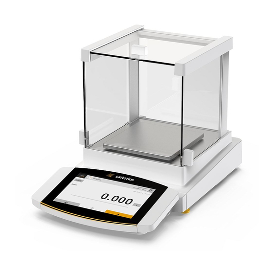
- Page 1 Operating Instructions Original Operating Instructions Cubis ® MCA Models Semimicro, Analytical and Precision Balances 1000047984...
-
Page 3: Table Of Contents
Contents Contents 1 About these Instructions . . . . . . . . . . . . . . . . . . . . . . . . . . . 7 4 Operating Design . - Page 4 Contents 5.10 Installing Palm-operable Keys 7.7.11 Parameters in the “Connections / (Only for Devices with Interfaces / Serial Communication Motorized Draft Shield)..... . .51 over Network”...
- Page 5 Contents 8 Operation . . . . . . . . . . . . . . . . . . . . . . . . . . . . . . . . . . . . . . . . . 84 10 Malfunctions .
- Page 6 17 Sartorius Service . . . . . . . . . . . . . . . . . . .
-
Page 7: About These Instructions
About these Instructions About these Instructions Scope These instructions are part of the device. These instructions apply to the device in the following versions: Device Model Cubis semi-microbalance, with MCA125P-... | MCA125S-... | ® manual or motorized draft shield, MCA225P-... | MCA225S-... with or without ionizer Cubis analytical balance, with... -
Page 8: Other Symbols
About these Instructions 1.2.2 Other Symbols Required action: Describes actions which must be carried out. Result: Describes the result of the actions carried out. Text inside brackets refers to control and display items. Text inside brackets indicates status, warning, and error messages. -
Page 9: Safety Instructions
The safety of the device may be impaired or the quality marks may lose their validity. We recommend that any repair work, even that not covered by the warranty, is carried out by Sartorius Service or after consulting with Sartorius Service. Operating Instructions Cubis ®... -
Page 10: Personnel Qualification
A damaged device or worn parts may lead to malfunctions or cause hazards which are difficult to recognize. Only operate the device when it is safe and in perfect working order. Have any damage repaired immediately by Sartorius Service. Safety Information on the Device Symbols, e.g. warnings, safety stickers, are safety information for the handling of the device. -
Page 11: Electrical Equipment
Only use the original power supply cable and AC adapter. If the AC adapter or power supply cable must be replaced: Contact Sartorius Service. Do not repair or modify the power supply unit or power supply cables. Conduct in an Emergency If there is immediate danger of personal injury or if there is a risk of damage to the device, e.g., due to malfunctions or dangerous situations, the device... -
Page 12: Accessories, Consumables
− Risk of injury to persons − Damage to the device − Device malfunctions − Device failure Only use approved accessories and spare parts supplied by Sartorius. Only use accessories, consumables, and spare parts that are in proper working order. Glass Breakage Glass components can break if they fall or are handled incorrectly. -
Page 13: Device Description
Device Description Device Description Device Overview Fig. 1: Semi-microbalance with motorized draft shield with ionizer and electronics module (example) Pos. Name Description Weighing chamber Manufacturer’s ID label Not depicted Weighing module Electronics module Only for semi-microbalances with electronics module Leveling foot Motorically adjustable Palm-operated key Opens and closes the side and upper panel of the draft shield... -
Page 14: Draft Shield
Device Description Draft Shield Fig. 2: Precision balance with frame draft shield, analytical balance with motorized analytical draft shield, and precision balance with manual analytical draft shield (example) Pos . Name Description Frame draft shield Is placed on the shield plate. Analytical draft shield Can be opened at the door handle of the upper panel or at the door handles of the side panels. -
Page 15: Weighing Pan
Device Description Weighing Pan and Associated Components Fig. 3: Precision balance with frame draft shield, analytical balance with manual analytical draft shield, and precision balance with manual analytical draft shield (example) Pos . Name Description Weighing pan Pan support Only for models with pan support Shield plate Pan retainer Operating Instructions Cubis... -
Page 16: Connections And Components
9-pin, for connection to a PC or PLC Access switch Protects the device from changes to the device settings. Is sealed for conformity-assessed devices. Peripheral connection For connecting Sartorius accessories Power supply For connection to the power supply Slot For attaching a “Kensington” anti-theft device Operating Instructions Cubis ®... -
Page 17: Semi-Microbalance
Access switch Protects the device from changes to the device settings. Is sealed for conformity-assessed devices. Peripheral connection For connecting Sartorius accessories Weighing module connection For connecting the electronics module to the weighing module Power supply For connection to the power supply Operating Instructions Cubis ®... -
Page 18: Connections On The Display And Control Unit
Device Description Connections on the Display and Control Unit Fig. 7: Connections on the display and control unit (example) Pos . Name Description USB-C connection For USB mass storage devices USB-A connection For USB accessories, e.g. printers, USB mass storage devices, barcode scanners Ethernet connection For connecting an Ethernet cable Safety Equipment... -
Page 19: Protective Caps On The Electronics Module
Device Description 3.7.2 Protective Caps on the Electronics Module Fig. 9: Protective caps on the electronics module Pos . Name Description Protective cap for USB-A connection Plastic attachment hood, fastened to the device. Protective cap for USB-B connection Plastic attachment hood, fastened to the device. Protective cap for COM-RS232 connection Removable plastic sealing cap. -
Page 20: Conformity-Assessed Devices
Device Description Conformity-assessed Devices Some settings of conformity-assessed models are protected against user changes, e.g. “external calibration” for devices in accuracy class II. This measure is intended to ensure the suitability of the devices for use in legal metrology. Symbols on the Device Fig. -
Page 21: Operating Design
Operating Design Operating Design Operating Elements in the Main Menu Fig. 1: Operating elements in the main menu (example) Pos . Name Description Navigation and function bar − Enables navigation and searching in menus and lists. − In the “Settings” Menu: Displays the name of the menu. Available tasks Displays all tasks available for the active user. -
Page 22: Operating Elements In Task Management
Operating Design Operating Elements in Task Management Fig. 2: Operating elements in Task Management (example) Pos . Name Description Navigation and function bar − Enables navigation and searching in menus and lists. − Enables the addition of tasks. − Opens the QAPP Center. −... -
Page 23: In The Weighing Display
Operating Design Operating Elements in the Weighing Display Fig. 3: Weighing display (example) Pos . Name Description Application symbol Displays the symbol for the active application. Task name Displays the name of the active task. Date display Displays the current date. User name Displays the name of the active user profile. -
Page 24: Advanced Operator Guidance
Operating Design Advanced Operator Guidance Advanced applications have advanced operator guidance. Fig. 4: Advanced operator guidance (example) Pos . Name Description Weighing display with operator guidance Advanced operator guidance Guides the user through the active task. Includes 2 or 3 convertible displays depending on the selected application: −... -
Page 25: Messages
Operating Design Messages Fig. 5: Error message (example) Pos . Name Description Description Specifies the cause. Remedy Specifies the measures necessary to eliminate the cause of the message. Confirm Confirms and closes the message. Message type Indicates that the message is a status message, warning message, or an error message. -
Page 26: Status Center
Operating Design Status Center Fig. 6: Status Center (example) Pos . Name Description Messages Displays information, warning, and error messages. Leveling status Displays the status of the level. Status for the device Displays the general device information. Calibration and adjustment report Displays the data for the last adjustment and calibration. -
Page 27: Keypad
Operating Design Keypad The keypad is used for entering values in entry fields. If an entry field is activated: The alphanumeric keypad or numerical keypad appears. Fig. 7: Alphanumeric keypad and numerical keypad (example) Pos . Name Description Input field Input assistance Indicates which values can be entered in the entry field, e.g. only numbers. -
Page 28: Buttons In The Operating Display
Operating Design Buttons in the Operating Display 4.9.1 Buttons for Navigation or Organization in Displays Symbol Name Description [Menu] button Quits the active task and opens the main menu. [Back] button − Returns to the previous display. − In the main menu: Accesses the last-performed task. [Search] button Displays options for browsing tasks and list elements. -
Page 29: Buttons For Editing
Operating Design Symbol Name Description [10 Positions Right] button Jumps 10 positions to the right in tasks or list elements. [Service Information] button Opens the “Settings” / “Device Settings” / Service “Device Information” / “Service” menu. Information [Status Archive] button Opens an overview of all status messages, Archive warning messages, and error messages. -
Page 30: Buttons For Weighing, Printing, And Export Functions
Operating Design Symbol Name Description [Deselect All] button Deselects the selection for all elements of a list. [Cancel] button − Cancels the current process without saving the changed settings or values. − In the display for editing the print memory: Marks the selected value as invalid. [Edit] button Accesses the Adjustment Wizard for editing the displayed element, e.g. - Page 31 Operating Design Symbol Name Description [Tare 1] button Stores the current weight value in the tare 1 memory. Tare 1 [Tare 1 Entry] button Opens an entry field for manually entering the tare 1 value. 0.00 g [Delete Tare 1] button Deletes the tare 1 memory. [Start] button Starts the selected application.
-
Page 32: Displays In The Operating Display
Operating Design 4.10 Displays in the Operating Display Symbol Name Description [Leveling] display Indicates that the device is not leveled. [Print memory] display Indicates that elements are located in the print memory. [Unit symbol] display Indicates the set weight unit, e.g. [g] for “grams”. [Result] display Indicates whether the weight value being displayed Gross... -
Page 33: User Management
Operating Design 4.11 User Management 4.11.1 User Profiles In the factory, four user profiles are created for the device. One role is assigned to each user profile. Each role has rights to operate the device. The rights assigned to each role depend on which device functions the user has to use. -
Page 34: Menu Structure
Operating Design 4.14 Menu Structure 4.14.1 Main Menu Navigating in menus (see Chapter 4.15, page 41). Level 1 Level 2 Level 3 Description Task Displays all available tasks. management Opens a summary of the properties for the displayed task. QAPP Center QAPP package −... -
Page 35: Settings" Menu
Display the period until the next scheduled maintenance maintenance. Maintenance cycle Display the maintenance cycle. Website Display the website for Sartorius Service. Device qualification Display the qualification date. View data Display, sort, browse, or export the contents storage device of the data storage device. - Page 36 Operating Design Level 1 Level 2 Level 3 Description User 4 standard Display or edit the standard user profiles: management user profiles User name, description, role, language, user color profile, and login method. If the “User Management” extension has been configured in the QAPP Center: Display or edit additional user profiles, roles, and rules.
- Page 37 Operating Design Level 1 Level 2 Level 3 Description Weighing and Spreadsheet (CSV) Display all available print profiles. Print Profiles on USB Edit, create or delete the print profiles. PC direct PC direct (USB keyboard Display all available PC direct profiles. emulation) Edit, create or delete the PC direct profiles.
- Page 38 Operating Design Level 1 Level 2 Level 3 Description Connections SBI protocol Format Configure the settings for the data output and data output format. Output Define whether the output takes place with or without stability. Automatic output Activate or deactivate the output rate for automatic data output.
- Page 39 Operating Design Level 1 Level 2 Level 3 Description Device minUSP minUSP function If this extension has been activated in settings the QAPP Center: Activate or deactivate the minimum initial weight. Starting point of If this extension has been activated in operating range the QAPP Center: Define the starting point value.
- Page 40 Operating Design Level 1 Level 2 Level 3 Description Device Display settings Display brightness Define the brightness of the settings operating display. On | off switch Activate or deactivate the “energy saving” function. Color scheme Define the settings for the operating display color scheme if this extension has been configured in the QAPP Center.
-
Page 41: Navigating The Menus
Operating Design 4.15 Navigating the Menus Procedure To open a menu from the main menu: Tap on the desired menu button in the function bar. The menu opens and the name of the open menu is displayed in the navigation bar. To return to the main menu from other displays: Press the [Menu] button or press the [Back] button (multiple times) until the main menu is displayed. - Page 42 Operating Design If a value needs to be selected from a list: Scroll to the desired value in the display. In order to do so, swipe the display upwards or downwards. Press the desired value. To confirm the selection: Press the [OK] button. The selected value is saved and the list closes.
-
Page 43: Installation
Installation Installation Scope of Delivery Item Quantity Device Weighing pan Shield plate For models with pan support: Pan support AC adapter For models with a motorized draft shield: Palm-operated key Country-specific power supply cable with test seal USB connection cable In-use dust cover for display and control unit For models with analytical draft shield: Dust cover For models without a draft shield: In-use dust cover... -
Page 44: Selecting An Installation Site
Installation Selecting an Installation Site Procedure Make sure that the following conditions are met at the installation site: Condition Features Ambient conditions Suitability tested (see Chapter “15.3 Ambient Conditions”, page 107) Setup surface Stable, even surface that is not exposed to vibrations Not directly against a wall Sufficiently dimensioned for the device... -
Page 45: Removing The Display And Control Unit
Installation Removing the Display and Control Unit 5.4.1 Positioning the Display and Control Unit The display and control unit can be removed. This enables the flexible setup of the display and control unit at the workplace. Tool: 1 Torx Allen key, T20 Material: 1 soft support base Requirements... -
Page 46: Connecting The Ethernet Cable
Installation Connecting the Ethernet Cable Material: 1 Ethernet cable 1 soft support base Requirements − The weighing pan and the associated components have not been set up. − For a device with an analytical draft shield or flat glass draft shield: The side panels and upper panel have not been fitted. - Page 47 Installation Requirements − The weighing pan and the associated components have not been set up. − For a device with an analytical draft shield or flat glass draft shield: The side panels and upper panel have not been fitted. Procedure Turn the device on its side and place it on the soft support base. Remove the hook for below-balance weighing (1) from the retainer on the underside of the base of the device.
-
Page 48: Installing A Device With An Analytical Draft Shield Or Flat Glass Draft Shield
Installation Installing a Device with an Analytical Draft Shield or Flat Glass Draft Shield 5.7.1 Positioning the Weighing Pan and Associated Components Procedure If this relates to a device with a pan support: Place the shield plate (1) on the base of the weighing chamber (2). Hook the pin on the pan support into the clip on the pan retainer. -
Page 49: Installing The Analytical Draft Shield
Installation If this relates to a device without a pan support: Place the shield plate (2) into the weighing chamber. Place the weighing pan (1) into the recess in the shield plate. 5.7.2 Installing the Analytical Draft Shield Procedure Slide the upper panel into the guide rail (1). Gently push the upper panel down. -
Page 50: Installing The Flat Glass Draft Shield
Installation 5.7.3 Installing the Flat Glass Draft Shield Procedure Gently tilt the upper panel down. This enables the upper panel to slide completely into the slot (1). Slide the upper panel completely into the slot. Insert the side panel completely into the guide rails on the weighing module (2) and into the upper guide rails (1). -
Page 51: Connecting The Electronics Module
Installation Place the shield plate (3) on the device housing. Place the weighing pan (2) on the pan support. Place the frame draft shield (1) on the shield plate (3). Connecting the Electronics Module (Only for Semi-microbalance) Procedure Connect the connection cable to the electronics module’s weighing module connection. -
Page 52: Setting Up The Cable Entry (Only For Devices With A Manual Analytical Draft Shield)
Installation 5.11 Setting Up the Cable Entry (Only for Devices with a Manual Analytical Draft Shield) For models with a manual analytical draft shield, a cable can be fed into the weighing chamber, e.g. when using a temperature sensor. Procedure Lift the locking tab (1) on the rear panel of the device. -
Page 53: Acclimatization
Installation 5.12 Acclimatization When a cold device is brought into a warmer area: The temperature difference can lead to condensation of humidity in the device (moisture formation). Moisture in the device can lead to malfunctions. Allow the device to acclimatize for approx. 2 hours at the installation site. Ensure that the device is disconnected from the power supply during that time. -
Page 54: Getting Started
Getting Started Getting Started Procedure NOTICE Improper connection may damage the device! If the device is connected using electronic components, e.g. printer, PC: The device must be disconnected from the power supply. Ensure that the device is disconnected from the power supply. Connect the device using electronic components (see electronic components instructions). -
Page 55: Connecting The Power Supply
WARNING Severe injuries caused by using a defective power supply cable! Check the power supply cable for damage, e.g., cracks in the insulation. If required: Contact Sartorius Service. Check whether the country-specific power plug matches the power connections at the installation site. -
Page 56: System Settings
System Settings System Settings Performing System Settings Default settings can be adjusted for the device and the applications in order to align with the ambient conditions and individual operating requirements. The following settings are necessary to operate the device together with connected components: −... -
Page 57: Assigning A Password
System Settings Assigning a Password Procedure Log into the device using the user profile for which a password needs to be assigned. Open the “Settings / User Management” menu. Press the [Lock] button. The user password input field is displayed. Enter the desired password in the entry field and confirm with the [OK] button. -
Page 58: Setting Up Device For Network Printer Via Independent Wi-Fi Network
System Settings − The device communicates with a company network via Wi-Fi. The network printer is connected to the company network. All the device’s network functions can be used in the entire company network. This configuration has 2 restrictions: − The company network must have a DHCP server. −... -
Page 59: Via Company Network
System Settings 7.5.3 Setting Up Device for Network Printer via Company Network Requirements − The device administrator or service rights are activated via user management. − The company network has a DHCP server. − The network printer is connected to the company network. Procedure Open the “Settings / Connections / Network / Wi-Fi”... -
Page 60: Configuring Print Profiles
A description on installation for a website certificate is available as a PDF file in English entitled “Installation Instructions for Website Certificate”. These PDF files are available to download under “Cubis II MCA Firmware” ® via the Sartorius website www.sartorius.com. Operating Instructions Cubis ®... -
Page 61: Parameter List
[User Activated] button. Language Set the language for the user profile. User color profile Sartorius Standard* If the QAPP extension “Color Scheme” has been activated: Define a user color for the user profile. Login method Determine whether the user password is saved locally on the device or provided by an LDAP network server. -
Page 62: Parameters In The "Timer-Controlled Actions" Menu
System Settings 7.7.3 Parameters in the “Timer-controlled Actions” Menu Parameter Setting Values Explanation Start task Execution date Activates the date and time for starting the task. Repeat period Repeats in minutes, hours, days, months, or years. Name Saves a name for the timer-controlled action. Action execution Sets the action execution to cancelable or not cancelable. -
Page 63: Parameters In The "Weighing And Print Profiles
System Settings 7.7.4 Parameters in the “Weighing and Print Profiles / Weighing” Menu Parameter Setting Values Explanation Ambient Very stable Sets the ambient conditions to “very stable”: Activates a fast conditions change in the weight values in the event of a load change with a high output rate. - Page 64 System Settings Parameter Setting Values Explanation Stability Very high accuracy Sets the stability to “very high accuracy”. High accuracy Sets the stability to “high accuracy”. Medium accuracy* Sets the stability to “medium accuracy”. Fast Sets the stability to “fast”. Very fast Sets the stability to “very fast”.
- Page 65 System Settings Parameter Setting Values Explanation Available units The availability of units may depend on national legislation and is therefore country-specific. Multiple selection is possible. mg – milligrams The device displays the weight in milligrams. g – grams* The device displays the weight in grams. kg –...
-
Page 66: Parameters In The "Weighing And Print Profiles / Ydp30, Pc Direct
System Settings 7.7.5 Parameters in the “Weighing and Print Profiles / YDP30, PC Direct, or SBI Direct” Menu Parameter Setting Values Explanation GLP print Off* Deactivates the GLP print. The GLP print is always switched on. All printouts contain a GLP header and a GLP footer. GLP header Standard elements −... - Page 67 System Settings Parameter Setting Values Explanation Print mode Report with print Displays the data to be printed in the operating display (for YDP printer) preview* before printing. Immediate output Prints the determined data directly on the connected printer. without preview Paper Continuous* Continuously prints the individual printouts on the lineprint.
-
Page 68: Parameters In The "Weighing And Print Profiles / Pdf Or Csv" Menu
System Settings 7.7.6 Parameters in the “Weighing and Print Profiles / PDF or CSV” Menu Parameter Setting Values Explanation GLP print Deactivates the GLP print. The GLP print is always switched on. All printouts contain a GLP header and a GLP footer. GLP header Standard elements −... -
Page 69: Parameters In The "Connections / Connectors" Menu
System Settings 7.7.7 Parameters in the “Connections / Connectors” Menu Parameter Setting Values Explanation Connector name Saves the entered name for a USB stick. Destination directory Saves the name of a destination directory. YDP30-NET Connector name Saves the entered name for a YDP30-NET. IP or host Enter the IP or host address for the printer. -
Page 70: Parameters In The "Connections / Network" Menu
System Settings 7.7.8 Parameters in the “Connections / Network” Menu Parameter Setting Values Explanation General settings Host name Saves the device host name. Ethernet IPv4 method Sets the method to DHCP, Manual or Off. IPv4 address If “Manual” has been selected for the IP method: Saves the number of an IP address. -
Page 71: Parameters In The "Connections / Website / Web Services" Menu
System Settings 7.7.9 Parameters in the “Connections / Website / Web Services” Menu Parameter Setting Values Explanation Website access Deactivated Deactivates the display of the website for the device. On, without Sets the display options of the website for the device authentication* to “without authentication”. -
Page 72: Parameters In The "Connections / Interfaces / Serial Communication Over Network" (Ethernet) Menu
System Settings 7.7.11 Parameters in the “Connections / Interfaces / Serial Communication over Network” (Ethernet) Menu Parameter Setting Values Explanation Protocol Off* Deactivates the serial transmission via Ethernet. Enables SBI communication. The data is output to a PC or control unit. - Page 73 System Settings Parameter Setting Values Explanation Protocol QAPP direct Enables data entry and output to a data processing program via a QAPP direct connection. Only the special QAPPs, which are started by a task, can use the interface for their purposes of input and output.
-
Page 74: Parameters In The "Connections / Interfaces / Usb-B Interface
System Settings 7.7.13 Parameters in the “Connections / Interfaces / USB-B Interface” Menu Parameter Setting Values Explanation Protocol Off* Deactivates the USB-B connection. Enables SBI communication. The data is output to a PC or control unit. Enables the use of ESC commands from a PC to control the basic balance functions with ASCII protocol. -
Page 75: Parameters In The "Connections
System Settings 7.7.14 Parameters in the “Connections / SBI Protocol” Menu Parameter Setting Values Explanation Format Value without header The data output only exports the measured value without ID code. Value (with header)* The data output exports the measured value with ID codes. Date &... -
Page 76: Parameters In The "Connections / Connected Devices / Motion Sensor" Menu
System Settings 7.7.16 Parameters in the “Connections / Connected Devices / Motion Sensor” Menu (only for connected motion sensors) Parameter Setting Values Explanation Number 2 gestures (left, right)* Activates the control of functions with 2 gestures. of gestures Gestures: left, right. 4 gestures (left, right, Activates the control of functions with 4 gestures. -
Page 77: Parameters In The "Connections / Connected Devices / External Usb Keys (Only For Connected Peripheral Device)" Menu
System Settings 7.7.17 Parameters in the “Connections / Connected Devices / External USB Keys (only for connected peripheral device)” Menu Parameter Setting Values Explanation Press key 1 (F1) No action Deactivates the function of the connected device. Release key 1 (F2) Start / cancel taring Starts a taring process or cancels a taring process. -
Page 78: Parameters In The "Device Settings / Safe Weighing" Menu
System Settings 7.7.19 Parameters in the “Device Settings / Safe Weighing” Menu Parameter Setting Values Explanation isoCAL Deactivates the isoCAL function. Depending upon the national execution mode legislation, this setting is not possible in conformity-evaluated (calibrated) devices or else the device may only be operated in a restricted temperature range. -
Page 79: Parameters In The "Device Settings
System Settings 7.7.20 Parameters in the “Device Settings / Preload” Menu Parameter Setting Values Explanation Preload Set preload − Sets the load present on the device as a preload and therefore changes the zero point of the device. − Reduces the maximum capacity by the set preload. Delete preload −... -
Page 80: Parameters In The "Device Settings
System Settings 7.7.23 Parameters in the “Device Settings / Measurement Uncertainty” Menu Parameter Setting Values Explanation Active Off* If this extension has been activated in the QAPP Center: Disables the measurement uncertainty. If this extension has been activated in the QAPP Center: Activates the dynamic display of the measurement uncertainty for the weight value. -
Page 81: Parameters In The "Device Settings / Draft Shield" Menu (Only For Devices With A Motorized Draft Shield)
System Settings 7.7.25 Parameters in the “Device Settings / Electronic Signature” Menu Parameter Setting Values Explanation Sign report Off* If the QAPP extension has been activated: Deactivates electronic signature. If the QAPP extension has been activated: Activates electronic signature. * Factory setting 7.7.26 Parameters in the “Device Settings / Draft Shield”... -
Page 82: Parameters In The "Device Settings / Start-Up Behavior" Menu
ON key. Color scheme Sartorius Standard* If the QAPP extension has been activated: Selects the color scheme for the “Sartorius Standard” operating display. Additional color schemes can be unlocked via the QAPP Center. * Factory setting Operating Instructions Cubis... -
Page 83: Parameters In The "Device Settings / Sound (Loudspeaker)" Menu
System Settings 7.7.30 Parameters in the “Device Settings / Sound (Loudspeaker)” Menu Parameter Setting Values Explanation Touch sounds Activated Deactivates the acoustic signal for touch and keypad operation. Deactivated* Activates the acoustic signal for touch and keypad operation. Message sounds Activated Deactivates the acoustic signal for messages. -
Page 84: Operation
Operation Operation Switching the Device On and Off The device only delivers accurate values if it has reached the necessary operating temperature. The warm-up time after switching the device on must therefore be complied with. If the device is being switched on for the first time or if the device is switched on after being reset to factory settings: The Setup Wizard opens. -
Page 85: Logging Users In And Out
Operation Logging Users In and Out Procedure If the name of the desired user profile is displayed in the entry field (1) of the login display: Press the [Login] button. If the name of the desired user profile is not displayed in the entry field of the login display: Tap on the entry field in the login display. -
Page 86: Opening And Closing The Motorized Draft Shield
Operation Opening and Closing the Motorized Draft Shield (Only for Devices with a Motorized Draft Shield) 8.4.1 Opening Draft Shield by Pressing the Palm-operated Key Pressing the palm-operated key enables the motorized side and upper draft shield panels to be opened and closed. A palm-operated key can be used to control up to three doors simultaneously. -
Page 87: Activating Applications And Adding A Task
Operation Activating Applications and Adding a Task 8.5.1 Activating Applications All applications from the QAPP package “Essentials” are activated the device at the factory. Additional applications may be activated in the QAPP center. These applications and QAPP packages can be tested for 30 days free of charge, and after that require a license. Procedure Open Task Management. -
Page 88: Adding An Application To A Task
Operation 8.5.2 Adding an Application to a Task Applications must be added to a task so that they can run. Procedure Open Task Management. Press the [New] button. A list of all activated applications is displayed. To select an application: Press the desired application. The wizard for creating a new task starts. -
Page 89: Weighing
Operation Weighing NOTICE Chemicals may damage the device or accessories! Chemicals can attack the device or the connected accessories internally and externally. This may damage the device and accessories. Use appropriate containers when weighing chemicals. Procedure Start a task with weighing function. Zero the device. -
Page 90: Adjusting With The Isocal Function
Operation 8.10 Adjusting with the isoCAL Function The device can be automatically internally calibrated and adjusted using the isoCAL function. Requirements − The device is not located in the menu. − Alphanumeric inputs are not active. − The load on the weighing pan remains unchanged for 2 minutes. −... -
Page 91: Internally Calibrating
Operation 8.11 Internally Calibrating and Adjusting the Device Requirements The weighing pan is unloaded. Procedure Open the main menu. Select the “Internal Adjustment” task. The internal calibration | adjustment function is executed. If automatic leveling is set for a model with motorized adjusting feet: The device levels itself automatically. -
Page 92: Marking Saved Values As Invalid
Operation If additional values are to be saved: Remove the sample being weighed. Place the next sample on the weighing pan and press the [Confirm] button. Scan or type the lot ID into the entry field. Press the [OK] button. 8.12.2 Marking Saved Values as Invalid Procedure Press the [Print Memory] button. -
Page 93: Exiting The Task
Operation 8.12.5 Exiting the Task Procedure Press the [Exit] or [Menu] button. If additional values are to be saved in the print memory: A dialog for prematurely ending the task appears. To return to the weighing display and print the saved values: Tap on the [Yes] button and print the saved values. -
Page 94: Turning The Ionizer On | Off (Only For Devices With An Ionizer)
Operation 8.14 Turning the Ionizer On | Off (Only for Devices with an Ionizer) 8.14.1 Setting the Ionizer Procedure Open the “Settings / Device Settings / Ionizer” menu. Select manual or automatic activation for the “Ionizer Function” parameter. For the “Ionizer Intensity” parameter, select the desired intensity, e.g. weak. -
Page 95: Running The "Statistics" Application (From Qapp Package "Essentials")
Operation All resolutions for the weight value defined in the weighing profile for the active task are displayed in a list. Press the desired unit. To set the resolution for the selected unit: Press the desired resolution. To confirm the selection and return to the weighing display: Press the [OK] button. -
Page 96: Cleaning And Maintenance
Cleaning and Maintenance Cleaning and Maintenance Preparing a Device with an Analytical Draft Shield or Flat Glass Draft Shield Procedure Turn the device off. Disconnect the device from the power supply. To do so, disconnect the power supply cable from the wall outlet. Fully open the draft shield side panels and upper panel. -
Page 97: Preparing A Device
Cleaning and Maintenance Remove the weighing pan and all associated components from the weighing compartment, e.g. shield plate, pan support. Preparing a Device with a Frame Draft Shield Procedure Turn the device off. Disconnect the device from the power supply. To do so, disconnect the power supply cable from the wall outlet. -
Page 98: Assembling And Connecting The Device
Re-connect the device to the power supply (see Chapter “6.2 Connecting the Power Supply”, page 55). Maintenance Schedule Interval Component Action Chapter, page Monthly to every 2 years, depending Device Contact Sartorius Service 17, 121 on the operating conditions Operating Instructions Cubis ®... -
Page 99: Performing A Software Update
− The USB mass storage device is formatted with file system “FAT32”. Procedure Download the software update from the Sartorius website onto the USB mass storage device. If this relates to a zip file: Unzip the software update on the stick. The files must be saved at root level. -
Page 100: Performing A Qapp Center Update
− The USB mass storage device is formatted with file system “FAT32”. Procedure Download the QAPP center update from the Sartorius website onto the USB mass storage device. If this relates to a zip file: Unzip the QAPP center update on the stick. -
Page 101: Malfunctions
Hold down the palm-operated the motorized draft shield upper panel of the motorized draft key. If the problem continues to does not open or close. shield is not functional or is blocked. occur: Contact Sartorius Service. Operating Instructions Cubis ®... -
Page 102: Decommissioning
Decommissioning Decommissioning 11.1 Decommissioning the Device Procedure Turn the device off. Disconnect the device from the power supply. Disconnect the device from all connected devices and all accessories, e.g. printer or electronics module. If this relates to a device with an analytical draft shield or flat glass draft shield: Remove the draft shield side panels and upper panel (see Chapter “9.1 Preparing a Device with an Analytical Draft Shield or Flat Glass Draft Shield”, page 96). -
Page 103: Storage And Shipping
Store the device according to the ambient conditions (see Chapter “15.3 Ambient Conditions”, page 107). 13.2 Returning Device and Parts Defective devices or device components can be returned to Sartorius. Returned devices must be clean, decontaminated, and properly packed, e.g. in the original packaging. -
Page 104: Disposal
WARNING Risk of injury due to contaminated devices Devices contaminated with hazardous materials (NBC contamination) will not be accepted by Sartorius for repair or disposal. 14.2 Disposing of Device and Parts 14.2.1 Information on Disposal The device and the device accessories must be disposed of properly by disposal facilities. -
Page 105: Technical Data
Technical Data 15 Technical Data 15.1 Dimensions and Weight 15.1.1 Semi-microbalance With manual draft shield With motorized draft shield Unit Value Value Dimensions Weighing module (L × W × H) 450 × 240 × 373 450 × 240 × 373 Electronics module (L ×... -
Page 106: Power Supply
Technical Data 15.2 Power Supply 15.2.1 Device Only by Sartorius AC adapter YEPS03-15V0 15.2.2 AC Adapter Unit Value Item No. YEPS03-15V0 Primary AC voltage 100–240 (± 10%) Frequency 50–60 (± 5%) Current consumption, maximum Secondary DC voltage at 2 A output current 14.25–15.75... -
Page 107: Electromagnetic Compatibility
Technical Data 15.2.4 Electromagnetic Compatibility Interference resistance Suitable for use in industrial areas Transient emissions Class B Suitable for use in residential areas and areas that are connected to a low voltage network that also supplies residential buildings. 15.3 Ambient Conditions 15.3.1 Installation Site Unit... -
Page 108: Ambient Temperature
Technical Data 15.3.2 Ambient Temperature for the isoCAL Function MCA225S MCA225P MCA125S MCA125P Unit Value Value Value Value Scope of application as per Directive 2014/31/EU With isoCAL function °C +10–+30 +10–+30 +10–+30 +10–+30 Without isoCAL function °C +17–+27 +17–+27 +17–+27 +17–+27 MCA524S MCA524P MCA324S... -
Page 109: Materials
Technical Data 15.4 Materials Housing: Die-cast aluminum, plastic PBT, Optiwhite float glass and stainless steel 1.4401|1.4404, PA handles, aluminum trim Display and control unit: Die-cast aluminum, painted, float glass and plastic PBT, PP 15.5 Integrated Clock Unit Value Maximum deviation per month (RTC) 15.6 Backup Battery Unit Value... -
Page 110: Metrological Data
Technical Data 15.7 Metrological Data 15.7.1 Models MCA225S | MCA225P | MCA125S | MCA125P MCA225S MCA225P MCA125S MCA125P Unit Value Value Value Value Scale interval (d) 0.01 0.01/0.02/ 0.01 0.01 | 0.1 0.05 Maximum capacity (Max) 60/120/220 60 | 120 Repeatability at 5% load Standard deviation of the load values, 0.015... -
Page 111: Models Mca524S | Mca524P | Mca324S | Mca324P
Technical Data 15.7.2 Models MCA524S | MCA524P | MCA324S | MCA324P MCA524S MCA524P MCA324S MCA324P Unit Value Value Value Value Scale interval (d) 0.1/0.2/0.5 0.1/0.2/0.5 Maximum capacity (Max) 120/240/ 80/160/320 Repeatability at 5% load Standard deviation of the load values, 0.08 0.08 0.08... -
Page 112: Models Mca224S | Mca124S | Mca5203S | Mca5203P
Technical Data 15.7.3 Models MCA224S | MCA124S | MCA5203S | MCA5203P MCA224S MCA124S MCA5203S MCA5203P Unit Value Value Value Value Scale interval (d) 1/2/5 Maximum capacity (Max) 5200 1200/2400/ 5200 Repeatability at 5% load Standard deviation of the load values, 0.07 tolerance Standard deviation of the load values,... -
Page 113: Models Mca3203S | Mca2203S | Mca2203P | Mca1203S
Technical Data 15.7.4 Models MCA3203S | MCA2203S | MCA2203P | MCA1203S MCA3203S MCA2203S MCA2203P MCA1203S Unit Value Value Value Value Scale interval (d) 1 | 10 Maximum capacity (Max) 3200 2200 1010 | 2200 1200 Repeatability at 5% load Standard deviation of the load values, tolerance Standard deviation of the load values, typical value... -
Page 114: Models Mca623S | Mca623P | Mca323S | Mca5202S
Technical Data 15.7.5 Models MCA623S | MCA623P | MCA323S | MCA5202S MCA623S MCA623P MCA323S MCA5202S Unit Value Value Value Value Scale interval (d) 1 | 2 | 5 Maximum capacity (Max) 150 | 300 | 5200 Repeatability at 5% load Standard deviation of the load values, tolerance Standard deviation of the load values,... -
Page 115: Recommended Calibration Weight
Technical Data 15.8 Recommended Calibration Weight MCA225S MCA225P MCA125S MCA125P Unit Value Value Value Value External test weight Recommended accuracy class MCA524S MCA524P MCA324S MCA324P Unit Value Value Value Value External test weight Recommended accuracy class MCA224S MCA124S MCA5203S MCA5203P Unit Value Value... -
Page 116: Isocal Function
Technical Data 15.9 isoCAL Function 15.9.1 Models MCA225S | MCA225P | MCA125S | MCA125P | MCA324S | MCA324P | MCA224S | MCA124S | MCA2203S | MCA2203P | MCA1203S Unit Value isoCAL is triggered by the following criteria: In the event of a temperature change After a time interval After successful leveling 15.9.2 Models MCA524S | MCA524P | MCA5203S | MCA5203P | MCA3203S... -
Page 117: Interfaces
Pin 8: Request to Send (RTS) Pin 9: Not used 15.11.2 Specifications for the USB-A Interface Communication USB host (master) Connectable devices Sartorius printers, USB memory sticks, USB barcode scanners, USB keyboards 15.11.3 Specifications for the USB-B Interface Communication USB device (slave) Type of interface Virtual serial interface (virtual COM-port, VCP) and “PC direct”... -
Page 118: Accessories
Accessories 16 Accessories 16.1 Accessories This table contains an excerpt of the accessories that can be ordered. For information on other products, contact Sartorius Service. 16.1.1 Printers and Communication Item Quantity Order number Thermal transfer | thermal printer YDP30 for GLP | GMP printouts on continuous... -
Page 119: Displays And Input | Output Elements
Accessories 16.1.2 Displays and Input | Output Elements Item Quantity Order number MCE operating display with color 69MS0128 TFT display and touch screen Motion sensor for triggering a maximum YHS02MS of 4 functions via gesture control, selection via menu 16.1.3 Hardware for Pipette Calibration Item Quantity Order number... -
Page 120: Weighing Tables
Accessories 16.1.6 Weighing Tables Item Quantity Order number Weighing table Made from synthetic stone, with YWT03 vibration dampening Made from wood and synthetic stone YWT09 Wall console YWT04 16.1.7 Weighing Accessories Item Image Quantity Order number Weighing scoop made from 641214 chrome-nickel steel, L 90 mm ×... -
Page 121: Sartorius Service
When contacting Sartorius Service with questions about a system or in the event of malfunctions, be sure to have the device information close at hand e.g., serial number, hardware, firmware, and configuration. Consult the information on the manufacturer’s ID label and in the “General Device... - Page 122 Conformity Documents Original EG-/EU-Konformitätserklärung EC / EU Declaration of Conformity Hersteller Sartorius Lab Instruments GmbH & Co. KG 37070 Goettingen, Germany Manufacturer erklärt in alleiniger Verantwortung, dass das Betriebsmittel declares under sole responsibility that the equipment Geräteart Elektronische Präzisions-, Milligramm-, Analysen-, Semimikro-, Mikro-Klein- und Hochlastwaage Netzgerät...
-
Page 123: Declaration Of Conformity
Conformity Documents 18.2 UK Declaration of Conformity Operating Instructions Cubis ®... -
Page 124: Certificate Of Compliance
Project: 70185847 Date Issued: 2018-09-24 Issued to: Sartorius Lab Instruments GmbH & Co. KG Otto-Brenner-Strasse 20 Goettingen, Niedersachsen 37079 GERMANY The products listed below are eligible to bear the CSA Mark shown with adjacent indicators 'C' and 'US' for Canada and US or with adjacent indicator 'US' for US only or without either indicator for Canada only. - Page 125 Conformity Documents Certificate: Master Contract: 167555 70185847 Project: 70185847 Date Issued: 2018-09-24 APPLICABLE REQUIREMENTS CSA Standards: CAN/CSA-C22.2 No. 61010-1-12 Safety Requirements for Electrical Equipment for Measurement, Control, and Laboratory Use, Part 1: General Requirements UL Standards: UL Std. No. 61010-1 (3 Edition) - Safety Requirements for Electrical Equipment for Measurement, Control, and Laboratory Use - Part 1: General Requirements...
- Page 126 Sartorius Lab Instruments GmbH & Co. KG Otto-Brenner-Strasse 20 37079 Goettingen, Germany Phone: +49 551 308 0 www.sartorius.com The information and figures contained in these instructions correspond to the version date specified below. Sartorius reserves the right to make changes to the technology, features, specifications and design of the equipment without notice.
Need help?
Do you have a question about the Cubis MCA Series and is the answer not in the manual?
Questions and answers