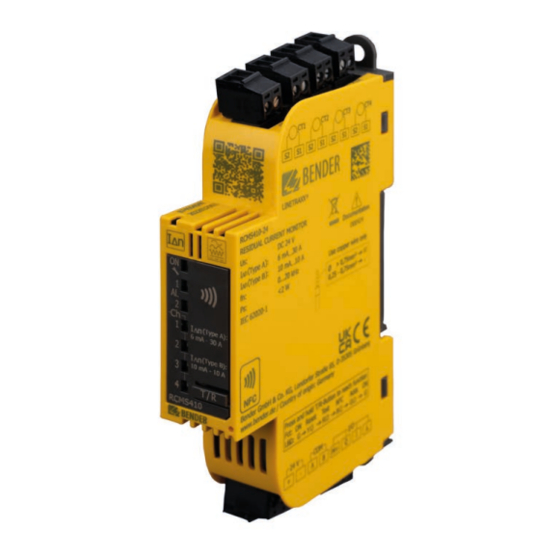
Bender LINETRAXX SmartDetect RCMS410 Manual
Four-channel dc, ac and pulse current sensitive residual current monitor for earthed ac, ac/dc and dc systems
Hide thumbs
Also See for LINETRAXX SmartDetect RCMS410:
- Quick start manual (4 pages) ,
- Manual (68 pages)

Related Manuals for Bender LINETRAXX SmartDetect RCMS410


Summary of Contents for Bender LINETRAXX SmartDetect RCMS410
- Page 1 LINETRAXX® SmartDetect RCMS410 Four-channel DC, AC and pulse current sensitive residual current monitor for earthed AC, AC/DC and DC systems RCMS410_D00424_00_M_XXEN / 09.2022 Manual EN...
- Page 2 Service and support for Bender products First-level support Technical support Carl-Benz-Strasse 8 • 35305 Gruenberg • Germany Telephone: +49 6401 807-760 0700BenderHelp * Fax: +49 6401 807-629 E-mail: support@bender-service.de Available from 7.00 a.m. to 8.00 p.m. 365 days a year (CET/UTC+1) * Landline German Telekom: Mon-Fri from 9.00 a.m.
-
Page 3: Table Of Contents
Signs and symbols ......................7 Training courses and seminars.................7 Delivery conditions .......................7 Inspection, transport and storage ................8 Warranty and liability....................8 Disposal of Bender devices ..................8 Safety ..........................8 Intended use ........................9 Function .................... 10 Device features ......................10 Functional description ..................... 10 2.2.1... - Page 4 Interfaces ..................19 Digital inputs and outputs (overview) ............... 19 Output M+ ........................20 4.2.1 Digital mode ....................... 20 4.2.2 Analogue mode ......................21 Digital input and output Q ..................22 Digital input I ......................25 Inputs CT1…4 ......................26 4.5.1 Measuring-current-transformer connection ...........
- Page 5 LINETRAXX® SmartDetect RCMS410 6.17 Time-behaviour registers ..................48 6.18 Monitoring-functions registers ................48 6.19 Measuring-current-transformer registers ............49 6.20 Device-error-code registers ..................49 6.21 Control-commands registers ................. 51 6.22 Function-control-commands registers .............. 51 Error – Cause – Error correction ........... 53 Technical data ..................
- Page 6 RCMS410_D00424_00_M_XXEN / 09.2022...
-
Page 7: General Instructions
Training courses and seminars www.bender.de > Know-how-> Seminars. Delivery conditions The conditions of sale and delivery set out by Bender apply. These can be obtained from Bender in printed or electronic format. The following applies to software products: "Software clause in respect of the licensing of standard software as part of deliveries. -
Page 8: Inspection, Transport And Storage
• Non-observance of technical data. • Repairs carried out incorrectly. • Use of accessories and spare parts not recommended by Bender. • Catastrophes caused by external influences and force majeure. • Mounting and installation with device combinations not recommended by the manufac- turer. -
Page 9: Intended Use
LINETRAXX® SmartDetect RCMS410 ! Risk of electrocution due to electric shock! anger Touching live parts of the system carries the risk of: - An electric shock - Damage to the electrical installation - Destruction of the device Before installing and connecting the device, make sure that the installation has been de- energised. -
Page 10: Function
• Device status and Alarm LED • Fault-memory behaviour selectable • RS-485 with Modbus RTU • NFC interface for device parameter setting via Bender Connect App with the device en- gerised or de-energised • Continuous CT-connection monitoring • Expanded functions available by enabling these function modules: –... -
Page 11: Connection Monitoring
LINETRAXX® SmartDetect RCMS410 fore t has elapsed, no alarm is signalled: The LEDs AL1, AL2 do not light up, and no prewarnung or main alarm is signalled via an interface. The set release time t starts when, after the alarm sta- tus was triggered, the measured value again reaches the release value. -
Page 12: Manual Self Test
Function 2.2.2 Manual self test When the T/R-button is operated (3…6 s), the device simulates an alarm status. All LEDs are illu- minated, and the outputs are activated. The alarm messages are output via the corresponding in- terfaces. When the storing of a fault in the memory is enabled, the alarm LEDs and the outputs re- main active until the fault memory is cleared by means of a reset. -
Page 13: Factory Settings Fac
LINETRAXX® SmartDetect RCMS410 2.2.5 Factory settings FAC There are two ways to carry out a reset: Factory settings without interface After restoring the factory settings, all previously changed settings are reset to the state upon delivery. The settings for the Modbus interface are not reset. Factory settings with interface After restoring the factory settings, all previously changed settings including the settings for the Modbus interface and the device address are reset to the state upon delivery. -
Page 14: Preset Function
The NFC interface can be used to transmit a previously configured device parameter setting di- rectly to the RCMS410. This function is available only via the Bender Connect App. You can find this app in the Appstores for and Android. -
Page 15: Function Modules
2.3.3 Connection of Type A external transformers This function module permits the use of measuring-current transformers by manufacturers other than Bender. When an external transformer is used, a winding number must be selected in the corresponding Modbus register (33104…33107). With ordering number B84604042 the incorporation of external transformers is already enabled as a default. -
Page 16: Mounting And Connection
Mounting and connection Mounting and connection Only qualified personnel are permitted to carry out the work necessary to install, com- mission and run a device or system. of electrocution due to electric shock! Touching live parts of the system carries the risk of: - A fatal electric shock - Damage to the electrical installation... -
Page 17: Connecting The Rcms410
LINETRAXX® SmartDetect RCMS410 DIN rail mounting Screw mounting Removal Mounting Ø M4 ISO7380-1, DIN84 < 2.5 mm Click! Fig. 3–3 Mounting Connecting the RCMS410 3.2.1 Connections overview Terminal Connection S1, S2 (CT4) Measuring-current transformer CT4 S1, S2 (CT3) Measuring-current transformer CT3 S1, S2 (CT2) Measuring-current transformer CT2 S1, S2 (CT1) -
Page 18: Wiring Diagram
Mounting and connection 3.2.2 Wiring diagram S1/S2: DI S1/S2: CT L1 L2 L3 N S1 (k) CT1…4 S2 (l) Verbraucher Load +24 V – RCMS410 – RS-485 L1 L2 L3 N ~/+ ~/– Fig. 3–5 RCMS410 wiring diagram Legend for wiring diagram For details see „4.6 RS-485 interface“... -
Page 19: Interfaces
LINETRAXX® SmartDetect RCMS410 – Interfaces Digital inputs and outputs (overview) Element Explanation Multi-functional output • Digital output: Signalling device states • Analogue voltage or current output: For the direct connection of analogue instruments that analyse and display measured values. Digital input/output •... -
Page 20: Output M
Interfaces Output M+ M+ is a multi-functional digital analogue output with reference to GND of the measuring sensor's supply voltage. 4.2.1 Digital mode Settings in registers 32500…32501 The following settings can be assigned to the output M+ in digital mode: High-active: In the active mode +24 V are applied to output M+ internally. -
Page 21: Analogue Mode
LINETRAXX® SmartDetect RCMS410 Permanently low: The output is permanently set to GND. In this manner e. g. an additional refer- ence for the digital input can be created. Alarm assignments permit assigning the following alarms to the output M+ in digital mode (reg- isters 32504…32519): Prewarning (AL1) AC/DC/RMS CH1…4 The output becomes active if AL1 of the selected measuring channel is present. -
Page 22: Digital Input And Output Q
Interfaces The overview shows how the measured values I (A) of the output signals (in A or V) are shown as Δ proportional values. Mode Analogue output 50 % ≥ 100 % I or set Δn RMS full scale value 0…20 mA 10 mA 20 mA... - Page 23 LINETRAXX® SmartDetect RCMS410 Input The following settings can be assigned to input Q: High-active: Event is carried out, when the digital input undergoes a slope change from low to high. Low-active: Event is carried out, when the digital input undergoes a slope change from high to low.
- Page 24 Interfaces In the passive mode, ≤ 32 V are connected externally (see technical data). The output switches the applied potential to GND. = 100 mA in max internally externally Permanently high: The output is permanently set to +24 V. In this manner e. g. an additional refer- ence for the digital input can be created.
-
Page 25: Digital Input I
LINETRAXX® SmartDetect RCMS410 Digital input I Settings in registers 32000…32001 The digital input "I" can read the status of a potential-free contact. Only voltages up to 3 V may be applied to input "I". The digital input "I" can trigger either a test, a reset or the combined function T/R (register 32301). As with the test and reset function, the combined function T/R is located at the T/R-button at the front. -
Page 26: Inputs Ct1
Interfaces Inputs CT1…4 4.5.1 Measuring-current-transformer connection RCMS410 Measuring-current transformer S2(l) S1(k) S2(l) S1(k) "Type A/type F" transformer Ensure that the measuring-current transformers are connected correctly. Terminal S1 must be connected to terminal "S1" (k) of the measuring-current transformer. Terminal S2 must be connected to terminal "S2" (l) of the measuring-current transformer. For further information on the connection of measuring-current transformers, refer to the corresponding manuals of the measuring-current transformers. -
Page 27: Connection Of Cts Of Other Manufacturers
LINETRAXX® SmartDetect RCMS410 Suitable measuring-current transformers Type B/type B+ Type A/type F Type A CTBS CTUB series CTAC series Wx series WR series WS series CTBS25 CTUB102 CTAC20 W0-S20 WR70x175S WS20x30 CTAC35 W1-S35 WR115x305S WS50x80 CTAC60 W2-S70 WR150x350S WS50x80S CTAC120 W3-S105 WR200x500S WS80x120... -
Page 28: Ct1
The RCMS410 has an RS-485 interface with Modbus RTU protocol. In a system setup it is therefore compatible with other Modbus RTU-capable device series from Bender, such as e. g. the RCMB300 series, RCMS150-01, and RCMB13 …-01. Up to 247 Modbus-RTU devices can be used on the bus. -
Page 29: Operation And Settings On The Device
∆ 10 mA - 10 A S 2.1 S 2.2 T / R S 1.1 S 1.2 RCMS410 Bender Fig. 5–6 RCMS410-24 control panel STATUS LED Multicoloured display of various operating modes. Operating mode START PHASE Device booting after start... -
Page 30: Alarm Leds
10 mA - 10 A Ch 3 RCMS410 • flashes in time with the STATUS LED when a measur- ing-current-transformer connection fault is present at the Bender Ch 4 corresponding channel T / R RCMS410 Bender... -
Page 31: Reset" Function
LINETRAXX® SmartDetect RCMS410 5.5.1 "RESET" Function The "RESET" function resets stored alarm states, and disables the limit value hysteresis for that in- stant. 5.5.2 "TEST" function The "TEST" function simulates a residual current of 1.5 x I for a period of 5 seconds. During this Δn period, the device has the following states: •... -
Page 32: Harmonic Analysis
Operation and settings on the device The address values are displayed via BCD code. Addresses can only be entered within the valid address range. When there is no input for a period of 5 minutes, the device automatically exis the address setting mode. The device then uses the currently set Modbus address. -
Page 33: Modbus Interface
LINETRAXX® SmartDetect RCMS410 Modbus interface Overview Description of the Modbus registers for RCMS41x devices. The following Modbus function codes are supported: • Holding register for reading out values (Read Holding Register; function code 0x03) • Register for device programming (Write Multiple Registers; function code 0x10) For a complete Modbus-protocol specification, visit http://www.modbus.org. -
Page 34: Device-Information Registers
Article number String UTF8 e.g.: B74604040 Serial number String UTF8 10 characters, e. g..: 2002123456 Manufacturer String UTF8 Bender GmbH & Co. KG Application D number UINT16 631 = D631 Application version number UINT16 xxx = Vx.xx Application build number... -
Page 35: Alarm/Measuring-Value Registers
LINETRAXX® SmartDetect RCMS410 Alarm/measuring-value registers Register Description Format Bytes Property Value/Unit/Comment Measured values (registers 999…1999) 0…n = number of active messages (device error, alarms, connection faults, …) Number of active messages UINT16 n is the number of messages that could also be attributed to an output (e. - Page 36 Modbus interface Register Description Format Bytes Property Value/Unit/Comment 1072 AC CH1 Float 1074 AC CH2 Float 1076 AC CH3 Float 1078 AC CH4 Float 1080 DC CH1 Float Min. residual-cur- 1082 DC CH2 Float rent measured Smalles measured value since the last Modbus query 1084 DC CH3 Float...
-
Page 37: Monitoring-Functions Registers
LINETRAXX® SmartDetect RCMS410 Monitoring-functions registers Prop- Register Description Format Bytes Value/Unit/Comment erty Monitoring functions (registers 2000…2050) 2000 UINT16 0 = OK 2001 UINT16 CT status 1 = short circuit 2002 UINT16 2 = interruption 2003 UINT16 Reload memory of 2014 UINT16 input/output "Q"... -
Page 38: Harmonic-Analysis Registers
Modbus interface Harmonic-analysis registers Registers (4000…4500) are only available with the optional function module "harmonic analysis". Otherwise these registers are reserved. Prop- Register Description Format Bytes Value/Unit/Comment erty Harmonic analysis, individual values H1…20 (registers 4000…4079) 4000 H1, CH1 UINT16 1st harmonic [mA] 4001 H2, CH1 UINT16... - Page 39 LINETRAXX® SmartDetect RCMS410 Prop- Register Description Format Bytes Value/Unit/Comment erty 4020 H1, CH2 UINT16 1st harmonic [mA] 4021 H2, CH2 UINT16 2nd harmonic [mA] 4022 H3, CH2 UINT16 3rd harmonic [mA] 4023 H4, CH2 UINT16 4th harmonic [mA] 4024 H5, CH2 UINT16 5th harmonic [mA] 4025...
- Page 40 Modbus interface Prop- Register Description Format Bytes Value/Unit/Comment erty 4040 H1, CH3 UINT16 1st harmonic [mA] 4041 H2, CH3 UINT16 2nd harmonic [mA] 4042 H3, CH3 UINT16 3rd harmonic [mA] 4043 H4, CH3 UINT16 4th harmonic [mA] 4044 H5, CH3 UINT16 5th harmonic [mA] 4045...
- Page 41 LINETRAXX® SmartDetect RCMS410 Prop- Register Description Format Bytes Value/Unit/Comment erty 4060 H1, CH4 UINT16 1st harmonic [mA] 4061 H2, CH4 UINT16 2nd harmonic [mA] 4062 H3, CH4 UINT16 3rd harmonic [mA] 4063 H4, CH4 UINT16 4th harmonic [mA] 4064 H5, CH4 UINT16 5th harmonic [mA] 4065...
-
Page 42: Thd, Rms Registers, H1
Modbus interface THD, RMS registers, H1…400 Prop- Register Description Format Bytes Value/Unit/Comment erty Harmonic analysis H1…400 (registers 4080…4500) Total of all harmonics (incl. fundamental harmonic) divided by 4080 THD CH1 UINT16 fundamental harmonic; value range: 0…10000 [%] 4081 THD validity CH1 UINT16 Validity of THD value;... -
Page 43: Modbus-Parameter Registers
LINETRAXX® SmartDetect RCMS410 6.10 Modbus-parameter registers Prop- Register Description Format Bytes Value/Unit/Comment Factory setting erty Modbus RTU parameters (register 32000) Last 2 digits of the 32000 Device address UINT16 1…247 serial number + 100 32001 Baud rate UINT32 9600, 19200, 38400, 57600, 115200 19200 1 = even 32003... -
Page 44: Registers Of Input/Output "Q
Modbus interface 6.12 Registers of input/output "Q" Prop- Factory Register Description Format Bytes Value/Unit/Comment erty setting Parameters of input/output "Q" (32400) 1 = output: passive 2 = output: high-active: 3 = output: low-active 32400 Mode UINT16 4 = output: permanently high 5 = output: permanently low 6 = input: high-active 7 = input: low-active... -
Page 45: Registers Of Output "M
LINETRAXX® SmartDetect RCMS410 6.13 Registers of output "M+" Prop- Factory Register Description Format Bytes Value/Unit/Comment erty setting Parameters of output "M+" (32500) 1 = output: passive 2 = output: high-active 3 = output: low-active 4 = output: permanently high 32500 Mode UINT16 5 = output: permanently low... -
Page 46: Registers Of Response-Value Parameters
Modbus interface Prop- Factory Register Description Format Bytes Value/Unit/Comment erty setting Alarm assignment, 0 = disabled 32518 UINT16 CT-connection fault 1 = enabled Alarm assignment, overload- 0 = disabled 32519 UINT16 ing of the measuring channels 1 = enabled 0…10 = Number of switching cycles until the 32520 Reload cycles UINT16... -
Page 47: Function And Operating-Characteristics Registers
LINETRAXX® SmartDetect RCMS410 6.15 Function and operating-characteristics registers Prop- Factory Register Description Format Bytes Value/Unit/Comment erty setting Function and response behaviour parameters (32700…32720) 1 = overcurrent 32700 CT1 function UINT16 2 = undercurrent 32701 CT2 function UINT16 3 = window function 4 = digital input: high-active 32702 CT3 function... -
Page 48: Alarm-Behaviour Registers
Modbus interface 6.16 Alarm-behaviour registers Prop- Factory Register Description Format Bytes Value/Unit/Comment erty setting Alarm behaviour parameters (32800 …32810) 32800 CH1 fault memory UINT16 32801 CH2 fault memory UINT16 0 = disabled 1 = enabled 32802 CH3 fault memory UINT16 32803 CH4 fault memory UINT16... -
Page 49: Measuring-Current-Transformer Registers
LINETRAXX® SmartDetect RCMS410 6.19 Measuring-current-transformer registers Prop- Factory Register Description Format Bytes Value/Unit/Comment erty setting CT - parameters (33100) Type of measuring-current 33100 UINT16 transformer, CT1 Type of measuring-current 33101 UINT16 transformer, CT2 1 = "type A"/ "type F" 2 = "type B"/ ”type B+” Type of measuring-current 33102 UINT16... - Page 50 Modbus interface Prop- Revers- Device Register Description Format Bytes Value/Unit/Comment erty ible faulty 58013 4.74 UINT16 474 = CT4 overload 475 = invalid settting of CT1: AC, DC and/or RMS 58014 4.75 UINT16 response values are too far apart 476 = invalid settting of CT2: AC, DC and/or RMS 58015 4.76 UINT16...
-
Page 51: Control-Commands Registers
LINETRAXX® SmartDetect RCMS410 6.21 Control-commands registers Prop- Factory Register Description Format Bytes Value/Unit/Comment erty setting Control commands (59000) 0 = disabled 59000 UINT16 1 = enabled (automatic disabling after 5 min) 59003 Start PRESET function UINT16 1 = start PRESET 1…4 (corresponds to measuring channels 59004 Start DC-offset fine matching... - Page 52 Modbus interface Prop- Register Description Format Bytes Value/Unit/Comment erty Function 2: Find device 2 = Selection of the "Find device" function 60000 Function selection UINT16 61918 60001 Pattern value part 1 UINT16 Security pattern must be written for the function to be executed.
-
Page 53: Error - Cause - Error Correction
LINETRAXX® SmartDetect RCMS410 Error – Cause – Error correction Error pattern Cause Correction Complete device Terminal blocks incorrectly plugged in Plug in terminal blocks correctly No device start Supply voltage incorrectly connected Establish correct wiring RS-485 Missing termination due to incorrect commissioning or Configure the terminating resistor, determine defective component. -
Page 54: Technical Data
Technical data Technical data Frequency responses of the filters The lines represent the area in which the device triggers a main alarm. no Filter Type A Filter 1000 10000 100000 1000 10000 100000 f [Hz] f [Hz] Type B Filter Type F Filter 1000 10000... - Page 55 LINETRAXX® SmartDetect RCMS410 60 Hz Filter 150 Hz Filter 1000 10000 100000 f [Hz] 1000 10000 100000 f [Hz] 180 Hz Filter 500 Hz Filter 1000 10000 100000 1000 10000 100000 f [Hz] f [Hz] 1 kHz Filter 2 kHz Filter 1000 10000 100000...
-
Page 56: Tabular Data
Technical data Tabular data Insulation coordination (IEC 60664-1/IEC 60664-3) Rated voltage U Rated voltage ............50 V ....see measuring-current-transformer manual Overvoltage category ..........III Connecting wires Rated impulse voltage ........800 V ....see measuring-current-transformer manual Rated insulation voltage ........50 V External transformer Pollution degree ............2 permissible continuous secondary current with.. -
Page 57: Standards & Certifications
......0.25…0.5 mm² EU Declaration of Conformity Stripping length ..........7 mm Tightening torque ......0.22…0.25 Nm Bender GmbH & Co. KG hereby declares that Conductor cross section AWG......28 … the device covered by the Radio Directive com- plies with Directive 2014/53/EU. - Page 58 Technical data RCMS410_D00424_00_M_XXEN / 09.2022...
- Page 59 LINETRAXX® SmartDetect RCMS410 RCMS410_D00424_00_M_XXEN / 09.2022...
- Page 60 Nachdruck und Vervielfältigung Reprinting and duplicating nur mit Genehmigung des Herausgebers. only with permission of the publisher. Bender GmbH & Co. KG Bender GmbH & Co. KG Postfach 1161 • 35301 Grünberg • Deutschland PO Box 1161 • 35301 Gruenberg • Germany Londorfer Str.
Need help?
Do you have a question about the LINETRAXX SmartDetect RCMS410 and is the answer not in the manual?
Questions and answers