Table of Contents
Advertisement
Quick Links
Advertisement
Table of Contents

Related Manuals for Raisecom Gazelle S1503i


Summary of Contents for Raisecom Gazelle S1503i
- Page 1 Gazelle S1503i (A) User Manual (Rel_01)
- Page 2 Website: http://www.raisecom.com Tel: 8610-82883305 Fax: 8610-82883056 Email: export@raisecom.com Address: Raisecom Building, No. 11, East Area, No. 10 Block, East Xibeiwang Road, Haidian District, Beijing, P.R.China Postal code: 100094 ----------------------------------------------------------------------------------------------------------------------------------------- Notice Copyright © 2014 Raisecom All rights reserved.
- Page 3 Objectives This document describes overview, hardware structure, technical specifications, serial server features, hardware installation, networking application, and management and maintenance of the Gazelle S1503i. The appendix lists terms, acronyms, and abbreviations involved in this document. Versions The following table lists the product versions related to this document.
- Page 4 Raisecom Gazelle S1503i (A) User Manual Preface General conventions Convention Description Times New Roman Normal paragraphs are in Times New Roman. Arial Paragraphs in Warning, Caution, Notes, and Tip are in Arial. Names of files, directories, folders, and users are in boldface.
-
Page 5: Table Of Contents
Raisecom Gazelle S1503i (A) User Manual Contents Contents 1 Overview ............................1 1.1 Introduction ..............................1 1.2 Features ................................1 1.2.1 High reliability ............................1 1.2.2 Various interface types ..........................2 1.2.3 Flexible networking performance ......................2 1.2.4 Strict QoS guarantee ..........................2 1.2.5 Complete secutity ensurance ........................ - Page 6 Raisecom Gazelle S1503i (A) User Manual Contents 2.7.1 Fiber ..............................16 2.7.2 Ethernet cable ............................18 2.7.3 Serial cable ............................21 2.7.4 AC power cable ............................. 22 2.7.5 DC power cable ............................. 24 2.7.6 Grounding cable ............................ 25 3 Technical specifications ......................28 3.1 Overall parameters ............................
- Page 7 Raisecom Gazelle S1503i (A) User Manual Contents 7.1 Management methods ............................ 46 7.1.1 CLI ................................ 46 7.1.2 Web ............................... 47 7.1.3 SNMP..............................47 7.2 Maintenance methods ............................. 47 7.2.1 Ping ............................... 47 7.2.2 Traceroute ............................. 48 7.2.3 Enviromental monitoring ........................48 7.2.4 RMON management ..........................
- Page 8 Figure 5-2 Installing the Gazelle S1503i to the guide rail ..................35 Figure 5-3 Removing the clamping rail connector ....................36 Figure 5-4 Installing the wall-mount plate to the rear panel of the Gazelle S1503i ..........36 Figure 5-5 Installing the wall-mount plate to the wall ..................37...
- Page 9 Figure 5-10 Connector for connecting the AC power cable ................. 40 Figure 6-1 Networking scheme of rail transportation ISCS by using the Gazelle S1503i ........43 Figure 6-2 Networking scheme of secure campus SDS by using the Gazelle S1503i.......... 44 Figure 6-3 Networking scheme of serial server by using the Gazelle S1503i ............
- Page 10 Table 1-1 Gazelle S1503i models ........................... 3 Table 2-1 Interfaces on the Gazelle S1503i ......................8 Table 2-2 Management and auxiliary interfaces on the Gazelle S1503i ..............8 Table 2-3 Parameters of the 1000BASE-X SFP optical interface ................9 Table 2-4 Parameters of the 100BASE-FX SFP optical interface ................9 Table 2-5 Parameters of the 10/100/1000BASE-T electrical interface ..............
- Page 11 Table 2-26 Technical specifications of the grounding cable ................. 26 Table 2-27 Technical specifications of the OT terminal ..................26 Table 3-1 Overall parameters of the Gazelle S1503i .................... 28 Table 3-2 Environmental requirements of the Gazelle S1503i ................29 Table 5-1 Power conditions of the Gazelle S1503i ....................
-
Page 12: Overview
(hereinafter referred to as the Gazelle S1503i), is characterized by all-GE interfaces, guide- rail chassis, full metal shell, fan-free design for heat dissipation, small size, low power consumption, and easy installation. The Gazelle S1503i can address the needs of the access- layer guide-rail switch in industrial control, intelligent transportation, and electrical ring network scenarios. -
Page 13: Various Interface Types
Support static Address Resolution Protocol (ARP), that is, bind the MAC address with the interface to protect the network from ARP attacks. Support storm control (including broadcast, unknown multicast, and unknown unicast packets), which effectively ensures the Gazelle S1503i to work normally in bad network conditions. Raisecom Technology Co., Ltd. -
Page 14: Comprehensive Management Modes
Support multiple software upgrading modes, such as, TFTP, FTP, SFTP, Network Management System (NMS), and Web. 1.3 Models The Gazelle S1503i can be divided by interface type into two models, as described in Table 1- Table 1-1 Gazelle S1503i models Model... -
Page 15: Hardware Structure
LEDs Power module Cables 2.1 Appearance Dimensions of the Gazelle S1503i chassis: 56 mm (Width) × 105 mm (Depth) × 135 mm (Height) The Gazelle S1503i can be installed in the following scenarios: Guide rail Wall 2.1.1 Front appearance... -
Page 16: Top Appearance
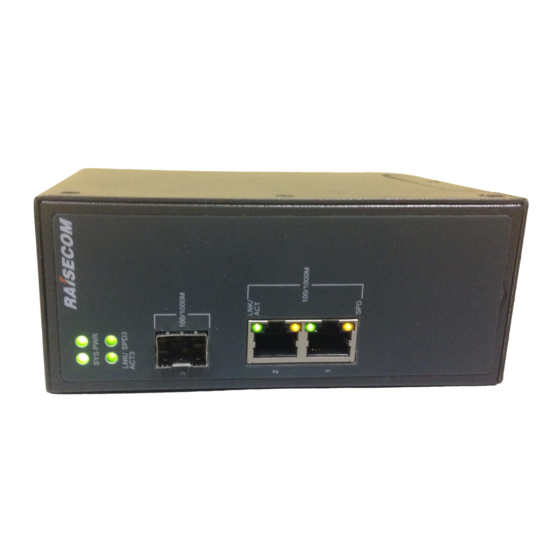
Service serial interface (RS-485/RS-232) Service interfaces 1–2 (LNK/ACT and SPD) Service interface 3 (SFP optical interface) LEDs (SYS, PWR, LNK/ACT3, TD, and RD) 2.1.2 Top appearance Figure 2-2 shows the top appearance of the Gazelle S1503i AC model. Raisecom Technology Co., Ltd. -
Page 17: Figure 2-2 Top Appearance Of The Gazelle S1503I Ac Model
Figure 2-2 Top appearance of the Gazelle S1503i AC model RST button Grounding terminal AC power interface (PWR) Figure 2-3 shows the top appearance of the Gazelle S1503i DC model (taking 24V/48V model for example). Figure 2-3 Top appearance of the Gazelle S1503i DC model RST button... -
Page 18: Rear Appearance
Raisecom Gazelle S1503i (A) User Manual 2 Hardware structure 2.1.3 Rear appearance Figure 2-4 shows the rear appearance of the Gazelle S1503i. Figure 2-4 Rear appearance of the Gazelle S1503i Clamping connector 2.2 Interfaces 2.2.1 Service interface The Gazelle S1503i provides multiple interfaces to carry services. -
Page 19: Management And Auxiliary Interfaces
100BASE-FX 1000BASE-X 2.2.2 Management and auxiliary interfaces Table 2-2 lists management and auxiliary interfaces on the Gazelle S1503i. Table 2-2 Management and auxiliary interfaces on the Gazelle S1503i Interface type Description Power interface 5-PIN Phoenix terminal (7.62 mm gap) for power input ... -
Page 20: Interface Parameters
Raisecom Gazelle S1503i (A) User Manual 2 Hardware structure 2.3 Interface parameters 2.3.1 1000BASE-X SFP optical interface Table 2-3 lists parameters of the 1000BASE-X SFP optical interface. Table 2-3 Parameters of the 1000BASE-X SFP optical interface Parameter Description Connector type... -
Page 21: Serial Interface
Phoenix terminal Electrical feature RS-485 Working mode Half duplex Baud rate 128 Baud–1 MBaud ≤ 1200 m Transmission distance 2.4 Lookup table for optical module parameters All Raisecom optical modules comply with RoHS and support DDM. Raisecom Technology Co., Ltd. -
Page 22: Ge Optical Module
Raisecom Gazelle S1503i (A) User Manual 2 Hardware structure 2.4.1 GE optical module Dual-fiber bidirectional (LC/PC) Table 2-8 Parameters of the GE (1250 Mbit/s) dual-fiber bidirectional optical module Model Tx optical Overl Extinc Mode Transm wavelength wavelength power oadin tion... -
Page 23: Fe Optical Modules
-15 to -8 > -8 > 8.2 < -28 03/SS13-I mode USFP- Single- 1550 1260–1360 -15 to -8 > -8 > 8.2 < -28 03/SS15-I mode 2.5 LEDs Table 2-12 lists LEDs on the Gazelle S1503i. Raisecom Technology Co., Ltd. -
Page 24: Power Modules
Off: the serial interface is not receiving data. 2.6 Power modules 2.6.1 Functions The Gazelle S1503i is embedded with a DC or AC power module. Based on related industrial standards, it meets strict specifications and supports functions as below: Raisecom Technology Co., Ltd. -
Page 25: Appearance And Interfaces
Support NMS alarm for battery failure. 2.6.2 Appearance and interfaces The power interface on the Gazelle S1503i is a 5-PIN Phoenix terminal interface, of which two PINs are 7.62 mm from each other. AC power Figure 2-5 shows appearance of the AC power interface. -
Page 26: Specifictions
Figure 2-7 Appearance of the 24/48 VDC power interface There is one power input interface on the top of the DC power module. Interface type and description are as listed in Table 2-14. Table 2-14 DC power module on the Gazelle S1503i Power module Print... -
Page 27: Cables
2.7.1 Fiber Introduction The Gazelle S1503i supports the single-mode fiber and multi-mode fiber. These two kinds of fiber are same in appearance while different in color. The yellow one is single-mode fiber and the orange one is the multi-mode fiber. -
Page 28: Figure 2-8 Lc/Pc Fiber Connector
Raisecom Gazelle S1503i (A) User Manual 2 Hardware structure Choose a connector suitable for the optical interface. Otherwise, it may increase additional loss of fiber links, reduce transmission quality of services, or even damage the connector and optical interface. -
Page 29: Ethernet Cable
<- Optical interface Tx 2.7.2 Ethernet cable Introduction For the Gazelle S1503i, the Ethernet cable connects the Ethernet electrical interface and other devices. The Ethernet interface on the Gazelle S1503i is self-adaptive to straight-through cable mode and crossover cable mode. -
Page 30: Table 2-20 Technical Specifications Of The Ethernet Cable
Raisecom Gazelle S1503i (A) User Manual 2 Hardware structure PIN 4 Blue Blue PIN 5 White/Blue White/Blue PIN 6 Orange Green PIN 7 White/Brown White/Brown PIN 8 Brown Brown Table 2-20 lists technical specifications of the Ethernet cable. Table 2-20 Technical specifications of the Ethernet cable... -
Page 31: Figure 2-10 Wiring Of The Straight-Through Cable
Raisecom Gazelle S1503i (A) User Manual 2 Hardware structure Figure 2-10 Wiring of the straight-through cable Crossover cable The wiring of the 100 Mbit/s crossover cable is different from that of the 1000 Mbit/s crossover cable. One RJ45 connector of the 100 Mbit/s crossover cable follows EIA/TIA 568A standard wiring;... -
Page 32: Serial Cable
2.7.3 Serial cable Introduction The serial cable is used to connect the serial interface of the Gazelle S1503i to the peer device. It transmits status information and data collected from devices, such as sensors, detectors, Programmable Logic Controllers (PLCs), and intelligent terminals, to the standard TCP/IP network. -
Page 33: Ac Power Cable
Introduction The AC power cable supplies 110/220 VAC power and 110/220 VDC power from the power souring equipment to the power interface on the Gazelle S1503i, and then transmits power to the entire device. The AC power cables of the Gazelle S1503i are different according to local standards. -
Page 34: Figure 2-14 European Standard Ac Power Cable
Raisecom Gazelle S1503i (A) User Manual 2 Hardware structure Figure 2-14 European standard AC power cable The AC power cable which meets American standard is composed of the American standard 3-pin plug and coaxial cable, as shown in Figure 2-15. -
Page 35: Dc Power Cable
Introduction The DC power cable transmits DC current from the power souring equipment to the power interface of the Gazelle S1503i, and then transmits power to the entire device. Appearance The DC power cable is composed of the connector and conducting wire, as shown in Figure 2-16. -
Page 36: Grounding Cable
The grounding cable is used to connect the Gazelle S1503i to the ground. Appearance The grounding cable is composed of grounding terminals and the coaxial cable. The grounding terminal is usually an OT non-insulated terminal. -
Page 37: Table 2-26 Technical Specifications Of The Grounding Cable
Thickness of soldering lug: ≥ 0.6 mm Cross-sectional area of 16–15 AWG (1.2–1.5 mm the conducting wire The Gazelle S1503i is delivered without the grounding cable. If required, make the grounding cable on site according to technical specifications. Raisecom Technology Co., Ltd. - Page 38 Raisecom Gazelle S1503i (A) User Manual 2 Hardware structure The grounding cable cannot be longer than 30 m and should be as short as possible; otherwise, a grounding bar should be used instead. Raisecom Technology Co., Ltd.
-
Page 39: Technical Specifications
Raisecom Gazelle S1503i (A) User Manual 3 Technical specifications Technical specifications This chapter describes technical specifications of the Gazelle S1503i, including the following sections: Overall parameters EMC standards Environmental standards 3.1 Overall parameters Table 3-1 lists overall parameters of the Gazelle S1503i. -
Page 40: Emc Standards
Overload protection Supported Reverse connection protection Supported 3.2 EMC standards The Gazelle S1503i is compliant with the following Electromagnetic Compatibility (EMC) standards: Electro Magnetic Interference (EMI) meets CISPR 22 CLASS A related requirements. Static electricity meets IEC 61000-4-2 level 3 requirements. -
Page 41: Serial Server
Raisecom Gazelle S1503i (A) User Manual 4 Serial server Serial server This chapter describes features of the serial server of the Gazelle S1503i, including the following sections: Introduction Working modes Typical applications 4.1 Introduction The serial server, also known as a serial-interface network access server or interface redirector, is a device that transfers data between a serial interface (COM interface) and an Ethernet Local Area Network (LAN). -
Page 42: Typical Applications
UDP protocol. TCP Realport mode The serial server maps the serial interface on the Gazelle S1503i to the virtual serial interface of the local host through the serial interface drive program (rcVirtualCom). The user terminal software uses the virtual terminal just like the real serial interface of the local host. Therefore, all software or communication modules running on the original serial interface device can be used directly without any modification. -
Page 43: Managing Remote Network-Interface Devices Through Serial Interface
Raisecom Gazelle S1503i (A) User Manual 4 Serial server Figure 4-1 Managing the remote serial device through the serial interface 4.3.2 Managing remote network-interface devices through serial interface As shown in Figure 4-2, you can manage the remote device by configuring the serial interface of the switch to the RS-485 interface in half duplex mode after changing the interface of the remote device to the network interface. -
Page 44: Hardware Installation
Raisecom Gazelle S1503i (A) User Manual 5 Hardware installation Hardware installation This chapter describes hardware installation of the Gazelle S1503i, including the following sections: Preparing for installation Installing device Grounding device Connecting cables Powering on device ... -
Page 45: Electrostatic Conditions
5.1.4 Grounding conditions The Gazelle S1503i must be grounded and the grounding resistance should be no more than 1 Ω. Grounding properly is a necessity for lightning protection and anti-interference. 5.1.5 Other conditions Before installation, you should make sure that the corollary device is ready. -
Page 46: Installing Device On Wall
5 Hardware installation Figure 5-1 Connecting the clamping rail connector to the guide rail Step 2 Press hard to fix the Gazelle S1503i to the guide rail, as shown in Figure 5-2. Figure 5-2 Installing the Gazelle S1503i to the guide rail Step 3 Make sure that the clamping rail connector is connected to the guide rail tightly. -
Page 47: Figure 5-3 Removing The Clamping Rail Connector
5 Hardware installation Figure 5-3 Removing the clamping rail connector Step 2 Install the wall-mount plate to the rear panel of the Gazelle S1503i and clockwise screw the wall-mount plate tightly, as shown in Figure 5-4. Figure 5-4 Installing the wall-mount plate to the rear panel of the Gazelle S1503i Step 3 Install the wall-mount plate to the wall, as shown in Figure 5-5. -
Page 48: Grounding Device
5.3 Grounding device Connecting the protective grounding cable properly is an important guarantee to lightning protection, anti-electric shock and anti-interference. The Gazelle S1503i must be connected to the protective grounding cable correctly during installation, which helps avoid personal injury and equipment damage. -
Page 49: Connecting Cables
5.4.1 Connecting fiber The Gazelle S1503i supports the LC/PC fiber interface. When the Gazelle S1503i is not used, you should to put the dustproof cover on the optical interface to prevent dust and dirt from entering the optical interface so as to make sure that the Gazelle S1503i works normally. -
Page 50: Connecting Ethernet Cable
Follow following steps to connect the Ethernet cable: Step 1 Make the Ethernet cable according to specifications. Step 2 Align the Ethernet cable head with the Ethernet interface of the Gazelle S1503i and insert the Ethernet cable into the Ethernet interface gently, as shown in Figure 5-8. -
Page 51: Figure 5-9 Connector For Connecting The Dc Power Cable
Step 1 Make the AC power cable according to specifications. Step 2 Insert the AC power cable head into the power interface of the Gazelle S1503i and confirm full insertion, as shown in Figure 5-10. -
Page 52: Powering On Device
5.5 Powering on device Power on the Gazelle S1503i as below: Step 1 The Gazelle S1503i can be powered on after being inserted with the power cable and installed properly. Step 2 The Gazelle S1503i is powered on when the DC power LEDs (PWR1/PWR2) or AC power LED (PWR) is lightening up. -
Page 53: Networking Applications
100/1000 Mbit/s double-star redundant Ethernet. The Gazelle S3028i provides redundant guarantee for routers on the whole system through the VRRP protocol. The Gazelle S1503i is adopted to establish the redundant network and provide redundant channel for service transmission, thus enhancing network reliability. When the working device fails, the backup device can take charge of the data forwarding and provide transparent switching for users. -
Page 54: Secure Campus Sds
Gazelle S1503i (A) User Manual 6 Networking applications Figure 6-1 Networking scheme of rail transportation ISCS by using the Gazelle S1503i 6.2 Secure campus SDS Campus security is one of the fields attracting the most attention from the society at present. -
Page 55: Serial Server
TCP connection. The Gazelle S1503i can be applied in the scenario when not only the Ethernet but also the bus asynchronous serial interface accesses the network. You can configure the serial interface... -
Page 56: Figure 6-3 Networking Scheme Of Serial Server By Using The Gazelle S1503I
Raisecom Gazelle S1503i (A) User Manual 6 Networking applications Figure 6-3 shows the networking scheme of serial server by using the Gazelle S1503i. Figure 6-3 Networking scheme of serial server by using the Gazelle S1503i Raisecom Technology Co., Ltd. -
Page 57: Management And Maintenance
Management methods Maintenance methods NView NNM system 7.1 Management methods You can use the following methods to access the Gazelle S1503i for management and maintenance: Command Line Interface (CLI) SNMP 7.1.1 CLI... -
Page 58: Web
The network management system can visit the agent only by specifying its community name correctly. If the community name carried in a SNMP packet is not authorized by the Gazelle S1503i, the packet will be discarded. -
Page 59: Traceroute
Raisecom Gazelle S1503i (A) User Manual 7 Management and maintenance 7.2.2 Traceroute Traceroute is used to discover the real route taking by the packet to transmit to the destination. Although the Ping feature can test the connectivity, it cannot record all network devices on the route limited by the IP head. -
Page 60: Nview Nnm System
Gazelle S1503i (A) User Manual 7 Management and maintenance The Gazelle S1503i is in support of data stream mirroring on the ingress interface, egress interface, and both the ingress and egress interfaces. Packets received and sent by the mirroring port will be copied to the monitor port for analysis and monitoring after port mirroring is enabled. -
Page 61: Figure 7-1 Orientation Of The Nview Nnm System
Raisecom Gazelle S1503i (A) User Manual 7 Management and maintenance Work as the uniform platform for all manageable devices of Raisecom. Uniformly manage data network and transport network. Provide strong NE-level management and subnet-level management. Provide northbound interfaces for integration with the OAM system, such as COBRA, SNMP, JDBC, and SOCKET interfaces. -
Page 62: Appendix
Raisecom Gazelle S1503i (A) User Manual 8 Appendix Appendix This chapter lists terms, acronyms, and abbreviations involved in this document, including and following sections: Terms Acronyms and abbreviations 8.1 Terms A series of ordered rules composed of permit | deny sentences. These... - Page 63 Raisecom Gazelle S1503i (A) User Manual 8 Appendix CHAP is a widely supported authentication method in which a representation of the user's password, rather than the password itself, is sent during the authentication process. With CHAP, the remote access server sends a challenge to the remote access client. The remote access...
- Page 64 Raisecom Gazelle S1503i (A) User Manual 8 Appendix In a communication link, both parties can receive and send data Full duplex concurrently. Generic Framing Procedure (GFP) is a generic mapping technology. It can group variable-length or fixed-length data for unified adaption,...
- Page 65 Raisecom Gazelle S1503i (A) User Manual 8 Appendix Link Aggregation A protocol used for realizing link dynamic aggregation. The LACPDU Control is used to exchange information with the peer device. Protocol (LACP) Multi-mode In this fiber, multi-mode optical signals are transmitted.
- Page 66 Raisecom Gazelle S1503i (A) User Manual 8 Appendix 802.1Q in 802.1Q (QinQ), also called Stacked VLAN or Double VLAN, is extended from 802.1Q and defined by IEEE 802.1ad recommendation. This VLAN feature allows the equipment to add a VLAN tag to a tagged packet. The implementation of QinQ is to add a...
-
Page 67: Acronyms And Abbreviations
Raisecom Gazelle S1503i (A) User Manual 8 Appendix STP can be used to eliminate network loops and back up link data. It Spanning Tree blocks loops in logic to prevent broadcast storms. When the unblocked Protocol (STP) link fails, the blocked link is re-activated to act as the backup link. - Page 68 Raisecom Gazelle S1503i (A) User Manual 8 Appendix BPDU Bridge Protocol Data Unit Base Transceiver Station Committed Access Rate Channel Associated Signaling Committed Burst Size Customer Edge CHAP Challenge Handshake Authentication Protocol CIDR Classless Inter-Domain Routing Committed Information Rate CIST...
- Page 69 Raisecom Gazelle S1503i (A) User Manual 8 Appendix Ethernet in the First Mile Electro Magnetic Compatibility Electro Magnetic Interference Electro Magnetic Susceptibility ERPS Ethernet Ring Protection Switching Electro Static Discharge Frame Check Sequence Fast Ethernet FIFO First Input First Output...
- Page 70 Raisecom Gazelle S1503i (A) User Manual 8 Appendix Internet Service Provider ITU-T International Telecommunications Union - Telecommunication Standardization Sector LACP Link Aggregation Control Protocol LACPDU Link Aggregation Control Protocol Data Unit Local Area Network LCAS Link Capacity Adjustment Scheme LLDP...
- Page 71 Raisecom Gazelle S1503i (A) User Manual 8 Appendix Object Identifiers Option 82 DHCP Relay Agent Information Option OSPF Open Shortest Path First P2MP Point to Multipoint Point-to-Point PADI PPPoE Active Discovery Initiation PADO PPPoE Active Discovery Offer PADS PPPoE Active Discovery Session-confirmation...
- Page 72 Raisecom Gazelle S1503i (A) User Manual 8 Appendix RSTP Rapid Spanning Tree Protocol RSVP Resource Reservation Protocol RTDP Raisecom Topology Discover Protocol SCADA Supervisory Control And Data Acquisition Signal Fail Small Form-factor Pluggable SFTP Secure File Transfer Protocol Service Level Agreement...
- Page 73 Raisecom Gazelle S1503i (A) User Manual 8 Appendix VRRP Virtual Router Redundancy Protocol Wide Area Network Weight Round Robin Raisecom Technology Co., Ltd.
- Page 74 Address Raisecom Building, No. 11, East Area, No. 10 Block, East Xibeiwang Road, Haidian District, Beijing, P.R.China Postal code: 100094 Tel: +86-10-82883305 Fax: 8610-82883056 http://www.raisecom.com Email: export@raisecom.com...
Need help?
Do you have a question about the Gazelle S1503i and is the answer not in the manual?
Questions and answers