Table of Contents
Advertisement
Quick Links
Advertisement
Table of Contents

Related Manuals for Raisecom Gazelle S1000i-LI


Summary of Contents for Raisecom Gazelle S1000i-LI
- Page 1 Gazelle S1000i-LI (A) User Manual (Rel_02)
- Page 2 Website: http://www.raisecom.com Tel: 8610-82883305 Fax: 8610-82883056 Email: export@raisecom.com Address: Raisecom Building, No. 11, East Area, No. 10 Block, East Xibeiwang Road, Haidian District, Beijing, P.R.China Postal code: 100094 ----------------------------------------------------------------------------------------------------------------------------------------- Notice Copyright © 2019 Raisecom All rights reserved.
- Page 3 Objectives This document describes overview, hardware structure, technical specifications, serial server features, hardware installation, networking application, and management and maintenance of the Gazelle S1000i-LI. The appendix lists terms, acronyms, and abbreviations involved in this document. Versions The following table lists the product versions related to this document.
- Page 4 Raisecom Gazelle S1000i-LI (A) User Manual Preface Conventions Symbol conventions The symbols that may be found in this document are defined as below. Symbol Description Indicate a hazard with a medium or low level of risk which, if not avoided, could result in minor or moderate injury.
- Page 5 Raisecom Gazelle S1000i-LI (A) User Manual Preface Fixed known bugs. Issue 01 (2017-10-30) Initial commercial release Raisecom Proprietary and Confidential Copyright © Raisecom Technology Co., Ltd.
-
Page 6: Table Of Contents
Raisecom Gazelle S1000i-LI (A) User Manual Contents Contents 1 Overview ............................1 1.1 Introduction ..............................1 1.2 Characteristics ..............................2 1.2.1 High reliability ............................2 1.2.2 Various interface types ..........................2 1.2.3 Powerful PoE power supply ........................2 1.2.4 Flexible networking performance ......................3 1.2.5 Complete security guarantee ........................ - Page 7 Raisecom Gazelle S1000i-LI (A) User Manual Contents 2.7.2 AC power cable ............................. 28 2.7.3 DC power cable ............................. 30 2.7.4 RJ45 Console cable 1 ..........................31 2.7.5 RJ45 Console cable 2 ..........................32 2.7.6 Mini-USB cable ............................ 33 2.7.7 Fiber ..............................34 2.7.8 Ethernet cable ............................
- Page 8 Raisecom Gazelle S1000i-LI (A) User Manual Contents 6.1.1 CLI ................................ 65 6.1.2 Web ............................... 66 6.1.3 SNMP..............................66 6.2 Maintenance methods ............................. 66 6.2.1 Ping ............................... 66 6.2.2 Traceroute ............................. 67 6.2.3 Enviromental monitoring ........................67 6.2.4 RMON management ..........................67 6.2.5 System log .............................
- Page 9 Raisecom Gazelle S1000i-LI (A) User Manual Figures Figures Figure 1-1 Appearance of the Gazelle S1000i-2GF-8FE-LI .................. 1 Figure 2-1 Front appearance of the Gazelle S1000i-2GF-4FE-LI ................6 Figure 2-2 Front appearance of the Gazelle S1000i-2GF-8FE-LI ................7 Figure 2-3 Front appearance of the Gazelle S1000i-4GF-16FE-LI ................ 8 Figure 2-4 Front appearance of the Gazelle S1000i-4GX-16FE-LI ...............
- Page 10 Raisecom Gazelle S1000i-LI (A) User Manual Figures Figure 2-2 Wiring of the Mini-USB Console cable ....................34 Figure 2-3 LC/PC fiber connector ........................35 Figure 2-4 Ethernet cable ............................. 36 Figure 2-5 Wiring of the straight-through cable ....................38 Figure 2-6 Wiring of the 100 Mbit/s crossover cable ................... 38 Figure 2-7 Wiring of the 1000 Mbit/s crossover cable ..................
- Page 11 Raisecom Gazelle S1000i-LI (A) User Manual Tables Tables Table 1-1 Models ..............................4 Table 2-1 Interfaces .............................. 16 Table 2-2 Management and auxiliary interfaces ....................18 Table 2-3 Parameters of the RJ45 Console interface .................... 18 Table 2-4 Parameters of the Mini-USB Console interface ................... 19 Table 2-5 Parameters of the 1000BASE-X SFP optical interface ................
- Page 12 Table 3-2 Software features ..........................42 Table 3-3 Reliability indexes ..........................44 Table 3-4 Environmental requirements ........................ 45 Table 4-1 Power conditions of the Gazelle S1000i-LI ..................46 Table 4-2 Items to be checked after installation ....................60 Raisecom Proprietary and Confidential...
-
Page 13: Overview
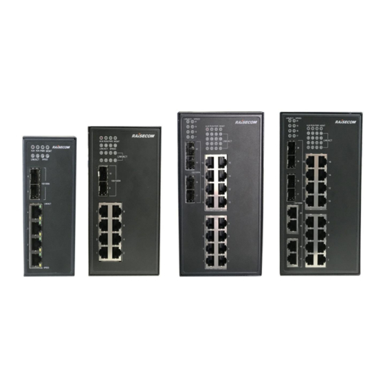
Raisecom Gazelle S1000i-LI (A) User Manual 1 Overview Overview This chapter is an overview of the Gazelle S1000i-LI, including the following sections: Introduction Characteristics Models 1.1 Introduction The 1000 Mbit/s industrial Ethernet switch Gazelle S1000i-LI (hereinafter referred to as the... -
Page 14: Characteristics
Provide the RST button to restart the entire device or restore factory settings. Provide 110/220 VAC power supply input. 1.2.3 Powerful PoE power supply The Gazelle S1000i-LI PoE model supports PoE, with the following characteristics: Support Endpoint PSE (PoE integrated in the Gazelle S1000i-LI). ... -
Page 15: Flexible Networking Performance
ARP attacks. Support storm control (including broadcast, unknown multicast, and unknown unicast packets), which effectively ensures the Gazelle S1000i-LI to work normally under bad network conditions. Support VLAN partition based on the IEEE 802.1Q to isolate physical interfaces. -
Page 16: Models
Raisecom Gazelle S1000i-LI (A) User Manual 1 Overview 1.3 Models Table 1-1 lists the models of the Gazelle S1000i-LI. Table 1-1 Models Model Description Provide two 100/1000 auto-negotiation SFP optical interfaces. Gazelle S1000i- Provide four 10/100BASE-TX auto-negotiation electrical 2GF-4FE-LI interfaces. -
Page 17: Hardware Structure
Raisecom Gazelle S1000i-LI (A) User Manual 2 Hardware structure Hardware structure This chapter describes the hardware structure of the Gazelle S1000i-LI, including the following sections: Appearance Interfaces Interface parameters Button LEDs Power supply ... -
Page 18: Figure 2-1 Front Appearance Of The Gazelle S1000I-2Gf-4Fe-Li
Raisecom Gazelle S1000i-LI (A) User Manual 2 Hardware structure Figure 2-1 Front appearance of the Gazelle S1000i-2GF-4FE-LI LEDs (ALM, RUN, PWR, MGMT, SPEED, and LNK/ACT) Service interfaces 5–6 (SFP optical interfaces) Service interfaces 1–4 (RJ45 electrical interfaces) and LEDs (LNK/ACT and SPEED) -
Page 19: Figure 2-2 Front Appearance Of The Gazelle S1000I-2Gf-8Fe-Li
Raisecom Gazelle S1000i-LI (A) User Manual 2 Hardware structure Figure 2-2 Front appearance of the Gazelle S1000i-2GF-8FE-LI LEDs (ALM, RUN, PWR, MGMT, SPEED, and LNK/ACT) Service interfaces 9–10 (SFP optical interfaces) Service interfaces 1–8 (RJ45 electrical interfaces) Gazelle S1000i-4GF-16FE-LI Figure 2-3 shows the front appearance of the Gazelle S1000i-4GF-16FE-LI. -
Page 20: Figure 2-3 Front Appearance Of The Gazelle S1000I-4Gf-16Fe-Li
Raisecom Gazelle S1000i-LI (A) User Manual 2 Hardware structure Figure 2-3 Front appearance of the Gazelle S1000i-4GF-16FE-LI LEDs (ALM, RUN, PWR, MGMT, SPEED, and LNK/ACT) Service interfaces 17–20 (SFP optical interfaces) Service interfaces 1–16 (RJ45 electrical interfaces) Gazelle S1000i-4GX-16FE-LI Figure 2-4 shows the front appearance of the Gazelle S1000i-4GX-16FE-LI. -
Page 21: Figure 2-4 Front Appearance Of The Gazelle S1000I-4Gx-16Fe-Li
Raisecom Gazelle S1000i-LI (A) User Manual 2 Hardware structure Figure 2-4 Front appearance of the Gazelle S1000i-4GX-16FE-LI LEDs (ALM, RUN, PWR, MGMT, SPEED, and LNK/ACT) Service interfaces 17–20 (1000 Mbit/s SFP Combo optical interfaces) Service interfaces 17–20 (1000 Mbit/s RJ45 Combo electrical interfaces) Service interfaces 1–16 (RJ45 electrical interfaces) -
Page 22: Figure 2-5 Front Appearance Of The Gazelle S1000I-2Gf-4Ge-Li
Raisecom Gazelle S1000i-LI (A) User Manual 2 Hardware structure Figure 2-5 Front appearance of the Gazelle S1000i-2GF-4GE-LI LEDs (ALM, RUN, PWR, MGMT, SPEED, and LNK/ACT) Service interfaces 5–6 (SFP optical interfaces) Service interfaces 1–4 (RJ45 electrical interfaces) and LEDs (LNK/ACT and SPEED) Gazelle S1000i-2GF-8GE-LI Figure 2-6 shows the front appearance of the Gazelle S1000i-2GF-8GE-LI. -
Page 23: Figure 2-6 Front Appearance Of The Gazelle S1000I-2Gf-8Ge-Li
Raisecom Gazelle S1000i-LI (A) User Manual 2 Hardware structure Figure 2-6 Front appearance of the Gazelle S1000i-2GF-8GE-LI LEDs (ALM, RUN, PWR, MGMT, SPEED, and LNK/ACT) Service interfaces 9–10 (SFP optical interfaces) Service interfaces 1–8 (RJ45 electrical interfaces) Gazelle S1000i-2GF-8GE-PWR-LI Figure 2-7 shows the front appearance of the Gazelle S1000i-2GF-8GE-PWR-LI. -
Page 24: Top Appearance
Raisecom Gazelle S1000i-LI (A) User Manual 2 Hardware structure Figure 2-7 Front appearance of the Gazelle S1000i-2GF-8GE-PWR-LI LEDs (ALM, RUN, PWR1, PWR2, MGMT, SPEED, and LNK/ACT) Service interfaces 9–10 (SFP optical interfaces) Service interfaces 1–8 (RJ45 electrical interfaces) and LEDs (LNK/ACT and POE) 2.1.2 Top appearance... -
Page 25: Figure 2-8 Top Appearance Of The Gazelle S1000I-2Gf-4Fe-Li And Gazelle S1000I-2Gf-4Ge-Li
Raisecom Gazelle S1000i-LI (A) User Manual 2 Hardware structure Figure 2-8 Top appearance of the Gazelle S1000i-2GF-4FE-LI and Gazelle S1000i-2GF-4GE-LI Ground terminal RST button Console interface (RJ45) AC power interface Gazelle S1000i-2GF-8FE-LI (A), Gazelle S1000i-2GF-8GE-LI, Gazelle S1000i-4GF- 16FE-LI, and Gazelle S1000i-4GX-16FE-LI Figure 2-9 shows the top appearance of the Gazelle S1000i-2GF-8FE-LI (A), Gazelle S1000i- 2GF-8GE-LI, Gazelle S1000i-4GF-16FE-LI, and Gazelle S1000i-4GX-16FE-LI. -
Page 26: Figure 2-10 Top Appearance Of The Gazelle S1000I-2Gf-8Fe-Li (H)
Raisecom Gazelle S1000i-LI (A) User Manual 2 Hardware structure RST button AC power interface Ground terminal Gazelle S1000i-2GF-8FE-LI (H) Figure 2-10 shows the top appearance of the Gazelle S1000i-2GF-8FE-LI (H). Figure 2-10 Top appearance of the Gazelle S1000i-2GF-8FE-LI (H) Console interface (Mini-USB interface) -
Page 27: Rear Appearance
Raisecom Gazelle S1000i-LI (A) User Manual 2 Hardware structure Figure 2-11 Top appearance of the Gazelle S1000i-2GF-8GE-PWR-LI Console interface (RJ45 interface) RST button DC power interface Ground terminal 2.1.3 Rear appearance Figure 2-12 shows the rear appearance of the Gazelle S1000i. -
Page 28: Interfaces
Figure 2-13 Rear appearance of the Gazelle S1000i Spring clip Rail clip Sliding connector 2.2 Interfaces 2.2.1 Service interface The Gazelle S1000i-LI provides multiple interfaces to access services. Table 2-1 lists interfaces on the Gazelle S1000i-LI. Table 2-1 Interfaces Model Print Interface type... - Page 29 Raisecom Gazelle S1000i-LI (A) User Manual 2 Hardware structure Model Print Interface type Description S1000i-2GF- 5–6 Support the following optical modules: 4FE-LI 1000BASE-X 100BASE-FX Gazelle 1–8 RJ45 10/100BASE-TX electrical interface S1000i-2GF- 9–10 Support the following optical modules: 8FE-LI ...
-
Page 30: Management And Auxiliary Interfaces
Table 2-2 Management and auxiliary interfaces Interface type Description Console RJ45 Console interface, used to connect the Gazelle S1000i-LI to a PC interface Mini-USB Console interface, used to connect the Gazelle S1000i-LI to a PC through a Mini-USB Console cable... -
Page 31: 1000Base-X Sfp Optical Interface
Raisecom Gazelle S1000i-LI (A) User Manual 2 Hardware structure Table 2-4 Parameters of the Mini-USB Console interface Parameter Description Connector type Mini-USB Duplex mode Duplex UART Electrical feature Baud rate 9600 baud Cable specifications 5-wire cable 2.3.3 1000BASE-X SFP optical interface Table 2-5 lists parameters of the 1000BASE-X SFP optical interface. -
Page 32: 10/100/1000Base-T Electrical Interface
IEEE 802.3 Supported network protocol 2.3.6 Optical module parameters All Raisecom modules comply with RoHS and all Raisecom optical modules support DDM. GE optical modules Dual-fiber bidirectional (LC/PC) Table 2-8 Parameters of GE (1250 Mbit/s) dual-fiber bidirectional optical modules... -
Page 33: Table 2-9 Parameters Of Ge (1250 Mbit/S) Single-Fiber Bidirectional Optical Modules
Raisecom Gazelle S1000i-LI (A) User Manual 2 Hardware structure Table 2-9 Parameters of GE (1250 Mbit/s) single-fiber bidirectional optical modules Model Tx optical Overloa Extinc Mode Transm wavelen wavelength power ding tion sensiti ission gth (nm) (nm) (EOL) point ratio... -
Page 34: Button
Gazelle S1000i-LI (A) Configuration Guide (CLI). Short press of the RST button for less than 3s will restart the Gazelle S1000i-LI. To prevent configuration files from being lost, save the current configurations before restarting the Gazelle S1000i-LI. -
Page 35: Table 2-13 Leds
Raisecom Gazelle S1000i-LI (A) User Manual 2 Hardware structure Table 2-13 LEDs Print Color Description Green: the system is being logged in to. Network Green Off: the system is not being logged in to. management Red: alarms are generated in the system. -
Page 36: Power Supply
2.6 Power supply 2.6.1 AC power supply Functions The Gazelle S1000i-LI is embedded with an AC power supply. Based on related industrial standards, it meets strict specifications and supports functions as below: The AC power supply has the following functions: ... -
Page 37: Dc Power Supply
Raisecom Gazelle S1000i-LI (A) User Manual 2 Hardware structure Table 2-14 AC power supply Print Description Connected to the ground terminal Connected to the N-wire input terminal of the AC power Connected to the L-wire input terminal of the AC power Specifications Table 2-15 lists specifications of the AC power supply. -
Page 38: Cables
The ground cable is used to connect the Gazelle S1000i-LI to the ground. A ground screw is on the top panel of the Gazelle S1000i-LI, used to fix the terminal of the ground cable with OT terminal after pressed connection, and other terminal of the ground cable can access to the ground. -
Page 39: Figure 2-16 Ground Cable
Raisecom Gazelle S1000i-LI (A) User Manual 2 Hardware structure Figure 2-16 Ground cable 1 Conducting wire Stripped end (connected to the OT terminal) 3 Insulating sheath OT terminal Figure 2-17 OT terminal Inner diameter of Inner diameter of Thickness of soldering... -
Page 40: Ac Power Cable
The AC power cable supplies 110/220 VAC power from the power souring equipment to the power interface on the Gazelle S1000i-LI, and then transmits power to the entire device. The AC power cables of the Gazelle S1000i-LI are different according to local standards, as listed in Table 2-20. -
Page 41: Figure 2-18 European Ac Power Cable
Raisecom Gazelle S1000i-LI (A) User Manual 2 Hardware structure Regional standard Description America POL-AC-American-3-pin/stripped-18AWG-1.5m/RoHS Appearance The AC power cable which meets European standard is composed of the European French- mode 3-pin plug and coaxial cable, as shown in Figure 2-18. -
Page 42: Dc Power Cable
Raisecom Gazelle S1000i-LI (A) User Manual 2 Hardware structure Table 2-22 Specifications of the American AC power cable Parameter Description Name POL-AC-American-3-pin/stripped-18AWG-1.5m/RoHS American 3-pin plug NEMA5-15 Connector 7.62-3pin-header/RoHS Color Outer Black (PVC insulating layer) Inner White (N), black (L), green (E) Type Copper core multi-strand power cable 18AWG (0.75 mm... -
Page 43: Rj45 Console Cable 1
2.7.4 RJ45 Console cable 1 Introduction The Console cable is used to connect the Console interface on the Gazelle S1000i-LI to the RS-232 serial interface of the console. It transmits configuration data signals. The console locally debugs and maintains the Gazelle S1000i-LI through the Console interface. -
Page 44: Rj45 Console Cable 2
2.7.5 RJ45 Console cable 2 Introduction The Console cable is used to connect the Console interface on the Gazelle S1000i-LI to the RS-232 serial interface on the console. It transmits configuration data signals. The console locally debugs and maintains the Gazelle S1000i-LI through the Console interface. -
Page 45: Mini-Usb Cable
Gazelle S1000i-LI through the maintenance console. Connectors at both ends of the configuration cable are as below: Mini-USB: connected to the Mini-USB Console interface on the Gazelle S1000i-LI USB: connected to the USB interface on the maintenance console Appearance Figure 2-1 shows the appearance of the Mini-USB Console cable. -
Page 46: Fiber
2.7.7 Fiber Introduction The Gazelle S1000i-LI supports the Single-Mode Fiber (SMF) and Multi-Mode Fiber (MMF). These two kinds of fiber are same in appearance while different in color. The yellow one is the SMF and the orange one is the MMF. -
Page 47: Figure 2-3 Lc/Pc Fiber Connector
Raisecom Gazelle S1000i-LI (A) User Manual 2 Hardware structure The Gazelle S1000i-LI can be connected to the Optical Distribution Frame (ODF) or optical interfaces of other devices through fiber. Table 2-27 lists the type and usage of the fiber. Table 2-27 Type and usage of the fiber... -
Page 48: Ethernet Cable
<- Optical interface Tx 2.7.8 Ethernet cable Introduction For the Gazelle S1000i-LI, the Ethernet cable connects the Ethernet electrical interface and other devices. The Ethernet interface on the Gazelle S1000i-LI is self-adaptive to straight-through cable mode and crossover cable mode. -
Page 49: Table 2-29 Wiring Of Eia/Tia 568A And Eia/Tia 568B Standards
Raisecom Gazelle S1000i-LI (A) User Manual 2 Hardware structure Table 2-29 lists the wiring of EIA/TIA 568A and EIA/TIA 568B standards. Table 2-29 Wiring of EIA/TIA 568A and EIA/TIA 568B standards Connector (RJ45) EIA/TIA 568A EIA/TIA 568B PIN 1 White/Green... -
Page 50: Figure 2-5 Wiring Of The Straight-Through Cable
Raisecom Gazelle S1000i-LI (A) User Manual 2 Hardware structure Figure 2-5 Wiring of the straight-through cable Crossover cable The wiring of the 100 Mbit/s crossover cable is different from that of the 1000 Mbit/s crossover cable. One RJ45 connector of the 100 Mbit/s crossover cable follows EIA/TIA 568A standard wiring;... -
Page 51: Figure 2-7 Wiring Of The 1000 Mbit/S Crossover Cable
Raisecom Gazelle S1000i-LI (A) User Manual 2 Hardware structure The 1000 Mbit/s crossover cable uses all 8 pins. The crossover is PIN 1 to PIN 3, PIN 2 to PIN 6, PIN 4 to PIN 7, and PIN 5 to PIN 8, as shown in Figure 2-7. -
Page 52: Technical Specifications
Raisecom Gazelle S1000i-LI (A) User Manual 3 Technical specifications Technical specifications This chapter describes technical specifications of the Gazelle S1000i-LI, including the following sections: Overall parameters Software features Protocols and standards 3.1 Overall parameters Table 3-1 lists overall parameters of the Gazelle S1000i-LI. -
Page 53: Software Features
44–57 VDC (with PoE power supply) 53–57 VDC (with PoE+ power supply) – Overload protection Supported Reverse polarity Supported protection 3.2 Software features Table 3-2 lists software features supported by the Gazelle S1000i-LI. Raisecom Proprietary and Confidential Copyright © Raisecom Technology Co., Ltd. -
Page 54: Table 3-2 Software Features
Raisecom Gazelle S1000i-LI (A) User Manual 3 Technical specifications Table 3-2 Software features Feature Description Logging in to the device through RJ45 Console/Telnet/SSH Basic features User management in login authentication, privilege allocation, and commands Hierarchical command management ... -
Page 55: Protocols And Standards
Raisecom Gazelle S1000i-LI (A) User Manual 3 Technical specifications Feature Description IGMP basis (assigning the multicast router interface, immediate Multicast leaving, multicast forwarding entries, aging time of the router interface, and IGMP ring network forwarding on the interface) ... -
Page 56: Laser Safety Class
The laser inside fiber may hurt your eyes. Do not stare into the optical interface directly during installation and maintenance. According to the Tx power of Laser, the Gazelle S1000i-LI laser belongs to Class 1 in safety class. In Class 1, the maximum Tx power on the optical interface is smaller than 10 dBm (10 mW). -
Page 57: Environmental Standards
AC power voltage falling and interruption meet IEC 61000-4-11 requirements. DC voltage dips and short interruptions immunity meet IEC 61000-4-29 requirements. 3.3.6 Environmental standards The Gazelle S1000i-LI is applicable to the industrial environment and should meet environmental requirements shown in Table 3-4. Table 3-4 Environmental requirements Parameter... -
Page 58: Hardware Installation
Raisecom Gazelle S1000i-LI (A) User Manual 4 Hardware installation Hardware installation This chapter describes hardware installation of the Gazelle S1000i-LI, including the following sections: Preparing for installation Installing device Grounding device Connecting cables Checking installation ... -
Page 59: Electrostatic Conditions
4.2 Installing device 4.2.1 Installing device on guide rail When the Gazelle S1000i-LI is taken out of the packing box, it is installed with the rail clip on the rear panel. The following installation and disassembling process aiming at two types of guide rails. -
Page 60: Figure 4-1 Connecting The Rail Clip To The Guide Rail
Raisecom Gazelle S1000i-LI (A) User Manual 4 Hardware installation Figure 4-1 Connecting the rail clip to the guide rail Step 2 Press hard to fix the spring clip to the guide rail tightly, as shown in Figure 4-2. Figure 4-2 Installing the rail clip to the guide rail Step 3 Press hard to secure the device on the guide rail, as shown in Figure 4-3. -
Page 61: Figure 4-3 Installing The Device On The Guide Rail
Figure 4-3 Installing the device on the guide rail Step 4 Ensure that the rail clip is connected to the guide rail tightly. Install the Gazelle S1000i-LI on the guide rail as below: Step 1 Connect the rail clip to the guide rail, as shown in Figure 4-4. -
Page 62: Figure 4-5 Installing The Device On The Guide Rail
Step 3 Ensure that the rail clip assembly is connected to the guide rail tightly. Removing device from guide rail Remove the Gazelle S1000i-LI from the guide rail as below: Step 1 Pull downward the device to make a gap between the rail clip and the guide rail, as shown in Figure 4-6. -
Page 63: Figure 4-7 Removing The Rail Clip Bottom From The Guide Rail
Raisecom Gazelle S1000i-LI (A) User Manual 4 Hardware installation Figure 4-7 Removing the rail clip bottom from the guide rail Step 3 Pull upward the device lightly and the spring clip is bounced. This operation separates the rail clip top from the guide rail. Then remove the device from the guide rail, as shown in Figure 4-8. -
Page 64: Installing Device On Wall
Raisecom Gazelle S1000i-LI (A) User Manual 4 Hardware installation Figure 4-9 Removing the sliding connector bottom from the guide rail Step 2 Pull the device bottom in the opposite direction of the guide rail to lean it and remove the rail clip bottom from the guide rail, as shown in Figure 4-10. -
Page 65: Figure 4-11 Removing The Rail Clip
Figure 4-11 Removing the rail clip Figure 4-12 Removing the rail clip Step 2 Install the wall-mount plate to the rear panel of the Gazelle S1000i-LI and clockwise screw the wall-mount plate tightly, as shown in Figure 4-13. Raisecom Proprietary and Confidential... -
Page 66: Installing Device On Rack Tray
4.2.3 Installing device on rack tray Install the Gazelle S1000i-LI on the rack tray as below: Step 1 Lay the Gazelle S1000i-LI on the tray, as shown in Figure 4-15. Raisecom Proprietary and Confidential Copyright © Raisecom Technology Co., Ltd. -
Page 67: Figure 4-15 Laying The Device On The Tray
4 Hardware installation Figure 4-15 Laying the device on the tray Step 2 Align the Gazelle S1000i-LI with holes of the tray, and fasten screws, as shown in Figure 4- Figure 4-16 Fastening the device to the tray Step 3 Use screws to fasten the brackets of the tray to the guide rail of the rack. Ensure that the Gazelle S1000i-LI is horizontally installed on the tray in the rack. -
Page 68: Grounding Device
4.3 Grounding device Connecting the ground cable properly is an important guarantee for lightning protection, anti-electric shock, and anti-interference. The Gazelle S1000i-LI must be connected to the ground cable correctly during installation, which helps avoid personal injury and device damage. -
Page 69: Connecting Cables
Connect the Ethernet cable as below: Step 1 Make the Ethernet cable according to specifications. Step 2 Align the Ethernet cable header with the Ethernet interface of the Gazelle S1000i-LI and insert the Ethernet cable into the Ethernet interface gently, as shown in Figure 4-20. -
Page 70: Connecting Power Cables
Step 1 Make the AC power cable according to specifications. Step 2 Insert the AC power cable header into the power interface of the Gazelle S1000i-LI and confirm full insertion, as shown in Figure 4-21. Figure 4-21 Connecting the connector of the AC power cable Step 3 Fastening screws of the AC power cable tightly, as shown in Figure 4-22. -
Page 71: Figure 4-22 Fastening Screws Of The Ac Power Cable
Step 1 Make the DC power cable according to specifications. Step 2 Insert the connector of the DC power cable into the power interface of the Gazelle S1000i-LI properly, and fasten spring screws at both sides of the connector, as shown in Figure 4-21. -
Page 72: Checking Installation
4.6 Powering on device Power on the Gazelle S1000i-LI as below: Step 1 The Gazelle S1000i-LI can be powered on after being inserted with the power cable and installed properly. Step 2 The Gazelle S1000i-LI is powered on when the power LED (PWR) is on. - Page 73 Gazelle S1000i-LI (A) User Manual 4 Hardware installation Step 3 The Gazelle S1000i-LI begins to operate properly after Power-on Self-Test (POST) and initialization. Interface LEDs indicate the working status of the interface (on, off, or blinking). Raisecom Proprietary and Confidential...
-
Page 74: Networking Applications
100/1000 Mbit/s double-star redundant Ethernet. The Gazelle S3028i provides redundant guarantee for routers on the whole system through the VRRP protocol. The Gazelle S1000i-LI is adopted to establish the redundant network and provide redundant channel for service transmission, thus enhancing network reliability. When the working device fails, the backup device can take charge of the data forwarding and provide transparent switching for users. -
Page 75: Intelligent Video Monitoring And Recording Networking For Expressway Vehicles
Figure 5-2 shows networking application of intelligent monitoring and recording system for expressway vehicles by using the Gazelle S1000i-LI. After the Gazelle S3028i in the police station is connected to the Gazelle S1000i-LI, the Layer 2 industrial Ethernet switch, IP high-definition bullet cameras, and car sensors form an intelligent monitoring and recording system to monitor vehicles and record information about illegal vehicles. -
Page 76: Figure 5-2 Intelligent Video Monitoring And Recording System For Expressway Vehicles
Raisecom Gazelle S1000i-LI (A) User Manual 5 Networking applications Figure 5-2 Intelligent video monitoring and recording system for expressway vehicles Raisecom Proprietary and Confidential Copyright © Raisecom Technology Co., Ltd. -
Page 77: Management And Maintenance
Maintenance methods NView NNM system 6.1 Management modes You can use the following methods to access the Gazelle S1000i-LI for management and maintenance: CLI: for details, see Gazelle S1000i-LI (A) Configuration Guide (CLI). Web: for details, see Gazelle S1000i-LI (A) Configuration Guide (Web). -
Page 78: Web
The network management system can visit the agent only by specifying its community name correctly. If the community name carried in a SNMP packet is not authorized by the Gazelle S1000i-LI, the packet will be discarded. -
Page 79: Traceroute
Raisecom Gazelle S1000i-LI (A) User Manual 6 Management and maintenance 6.2.2 Traceroute Traceroute is used to discover the real route taking by the packet to transmit to the destination. Although the Ping feature can test the connectivity, it cannot record all network devices on the route limited by the IP header. -
Page 80: Nview Nnm System
Gazelle S1000i-LI (A) User Manual 6 Management and maintenance The Gazelle S1000i-LI is in support of data stream mirroring on the ingress interface, egress interface, and both the ingress and egress interfaces. Packets received and sent by the mirroring port will be copied to the monitor port for analyses and monitoring after port mirroring is enabled. -
Page 81: Figure 6-1 Orientation Of The Nview Nnm System
Raisecom Gazelle S1000i-LI (A) User Manual 6 Management and maintenance Work as the uniform platform for all manageable devices of Raisecom. Uniformly manage data network and transport network. Provide strong NE-level management and subnet-level management. Provide northbound interfaces for integration with the OAM system, such as COBRA, SNMP, JDBC, and SOCKET interfaces. -
Page 82: Appendix
Raisecom Gazelle S1000i-LI (A) User Manual 7 Appendix Appendix This chapter lists terms, acronyms, and abbreviations involved in this document, including and following sections: Terms Acronyms and abbreviations 7.1 Terms A series of ordered rules composed of permit | deny sentences. These... - Page 83 Raisecom Gazelle S1000i-LI (A) User Manual 7 Appendix CHAP is a widely supported authentication method in which a representation of the user's password, rather than the password itself, is sent during the authentication process. With CHAP, the remote access server sends a challenge to the remote access client. The remote access...
- Page 84 Raisecom Gazelle S1000i-LI (A) User Manual 7 Appendix Generic Framing Procedure (GFP) is a generic mapping technology. It can group variable-length or fixed-length data for unified adaption, encapsulation making data services transmitted through multiple high-speed physical transmission channels. The cable used to connect the device to ground, usually a yellow/green coaxial cable.
- Page 85 Raisecom Gazelle S1000i-LI (A) User Manual 7 Appendix Link Aggregation A protocol used for realizing link dynamic aggregation. The LACPDU Control is used to exchange information with the peer device. Protocol (LACP) Link-state tracking is used to provide interface linkage scheme for specific application and it can extend range of link backup.
- Page 86 Raisecom Gazelle S1000i-LI (A) User Manual 7 Appendix PVLAN adopts Layer 2 isolation technology. Only the upper VLAN is Private VLAN visible globally. The lower VLANs are isolated from each other. If you (PVLAN) partition each interface of the switch or IP DSLAM device into a lower VLAN, all interfaces are isolated from each other.
-
Page 87: Acronyms And Abbreviations
Raisecom Gazelle S1000i-LI (A) User Manual 7 Appendix Simple Network Time SNTP is mainly used for synchronizing time of devices in the network. Protocol (SNTP) Single-Mode In this fiber, single-mode optical signals are transmitted. Fiber (SMF) STP can be used to eliminate network loops and back up link data. It Spanning Tree blocks loops in logic to prevent broadcast storms. - Page 88 Raisecom Gazelle S1000i-LI (A) User Manual 7 Appendix Boundary Clock Backup Designated Router BITS Building Integrated Timing Supply System BOOTP Bootstrap Protocol BPDU Bridge Protocol Data Unit Base Transceiver Station Committed Access Rate Channel Associated Signaling Committed Burst Size Customer Edge...
- Page 89 Raisecom Gazelle S1000i-LI (A) User Manual 7 Appendix EAPoL EAP over LAN Ethernet in the First Mile Electro Magnetic Compatibility Electro Magnetic Interference Electro Magnetic Susceptibility ERPS Ethernet Ring Protection Switching Electro Static Discharge Frame Check Sequence GARP Generic Attribute Registration Protocol...
- Page 90 Raisecom Gazelle S1000i-LI (A) User Manual 7 Appendix ITU-T International Telecommunications Union - Telecommunication Standardization Sector LACP Link Aggregation Control Protocol LACPDU Link Aggregation Control Protocol Data Unit Local Area Network LCAS Link Capacity Adjustment Scheme LLDP Link Layer Discovery Protocol...
- Page 91 Raisecom Gazelle S1000i-LI (A) User Manual 7 Appendix Option 82 DHCP Relay Agent Information Option P2MP Point to Multipoint Point-to-Point PADI PPPoE Active Discovery Initiation PADO PPPoE Active Discovery Offer PADS PPPoE Active Discovery Session-confirmation Password Authentication Protocol Protocol Data Unit...
- Page 92 Raisecom Gazelle S1000i-LI (A) User Manual 7 Appendix RSVP Resource Reservation Protocol RTDP Raisecom Topology Discover Protocol SCADA Supervisory Control And Data Acquisition Signal Fail Small Form-factor Pluggable SFTP Secure File Transfer Protocol Service Level Agreement SNMP Simple Network Management Protocol...
- Page 93 Raisecom Gazelle S1000i-LI (A) User Manual 7 Appendix Wide Area Network Weight Round Robin Raisecom Proprietary and Confidential Copyright © Raisecom Technology Co., Ltd.
- Page 94 Address Raisecom Building, No. 11, East Area, No. 10 Block, East Xibeiwang Road, Haidian District, Beijing, P.R.China Postal code: 100094 Tel: +86-10-82883305 Fax: 8610-82883056 http://www.raisecom.com Email: export@raisecom.com...
Need help?
Do you have a question about the Gazelle S1000i-LI and is the answer not in the manual?
Questions and answers