Table of Contents
Advertisement
Quick Links
Advertisement
Table of Contents

Related Manuals for Raisecom Gazelle S1020i-LI


Summary of Contents for Raisecom Gazelle S1020i-LI
- Page 1 Gazelle S1020i-LI (A) User Manual (Rel_02)
- Page 2 Website: http://www.raisecom.com Tel: 8610-82883305 Fax: 8610-82883056 Email: export@raisecom.com Address: Raisecom Building, No. 11, East Area, No. 10 Block, East Xibeiwang Road, Haidian District, Beijing, P.R.China Postal code: 100094 ----------------------------------------------------------------------------------------------------------------------------------------- Notice Copyright © 2020 Raisecom All rights reserved.
- Page 3 Gazelle S1020i-LI (A) User Manual Preface Preface Objectives This document describes the Gazelle S1020i-LI all-GE switches in terms of overview, hardware structure, technical specifications, hardware installation, networking applications, management, and maintenance. The appendix lists terms, acronyms, and abbreviations involved in this document.
- Page 4 Raisecom Gazelle S1020i-LI (A) User Manual Preface General conventions Convention Description Times New Roman Normal paragraphs are in Times New Roman. Arial Paragraphs in Warning, Caution, Notes, and Tip are in Arial. Boldface Buttons and navigation path are in Boldface.
-
Page 5: Table Of Contents
Raisecom Gazelle S1020i-LI (A) User Manual Contents Contents 1 Overview ............................1 1.1 Introduction ..............................1 1.2 Characteristics ..............................2 1.3 Overall parameters ............................2 1.4 Features ................................3 1.5 Applications..............................5 1.5.1 Crossroad video monitoring system application ..................5 1.6 Product model .............................. - Page 6 Raisecom Gazelle S1020i-LI (A) User Manual Contents 2.7.4 DC power cable ............................. 28 2.7.5 Fiber ..............................29 3 Technical specifications ......................32 3.1 Protocols and standards ..........................32 3.1.1 Compliance standards ........................... 32 3.1.2 Laser safety class ..........................32 3.1.3 Reliability indicators ..........................32 3.1.4 Safety standards ............................
- Page 7 Raisecom Gazelle S1020i-LI (A) User Manual Contents 6 Appendix ............................48 6.1 Terms ................................48 6.2 Acronym and abbreviations ..........................53 Raisecom Proprietary and Confidential Copyright © Raisecom Technology Co., Ltd.
- Page 8 Gazelle S1020i-LI (A) User Manual Figures Figures Figure 1-1 Appearance of the Gazelle S1020i-LI ....................2 Figure 1-2 Crossroad video monitoring system for expressway vehicles .............. 6 Figure 2-1 Front appearance of the Gazelle S1020i-2GF-4GE-LI-DCW24 ............9 Figure 2-2 Top appearance of the Gazelle S1020i-2GF-4GE-LI-DCW24 ............10 Figure 2-3 Front appearance of the Gazelle S1020i-2GF-8GE-LI-DCW24 ............
- Page 9 Raisecom Gazelle S1020i-LI (A) User Manual Figures Figure 4-7 Inserting the fiber ..........................40 Figure 4-8 Connecting the DC power connector ....................41 Figure 5-1 Location of the NView NNM system ....................47 Raisecom Proprietary and Confidential Copyright © Raisecom Technology Co., Ltd.
- Page 10 Gazelle S1020i-LI (A) User Manual Tables Tables Table 1-1 Overall parameters of the Gazelle S1020i-LI ..................3 Table 1-2 Features ..............................4 Table 1-3 Models of the Gazelle S1020i-LI ......................6 Table 2-1 Front panel of the Gazelle S1020i-2GF-4GE-LI-DCW24 ..............9 Table 2-2 Front panel of the Gazelle S1020i-2GF-8GE-LI-DCW24 ..............
- Page 11 Raisecom Gazelle S1020i-LI (A) User Manual Tables Table 2-24 Technical specifications of the DC power cable................. 29 Table 2-25 Type and usage of the fiber ........................ 29 Table 2-26 Wiring of the fiber ..........................30 Table 3-1 Reliability indicators ..........................33 Table 3-2 Environmental requirements ........................
-
Page 12: Overview
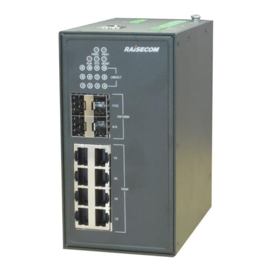
Product model 1.1 Introduction The Gazelle S1020i-LI GE industrial switch (hereinafter referred to as the Gazelle S1020i-LI) adopts an all-metal shell and fanless heat dissipation design, features small size and low power consumption, and is easy to install. It is designed to meet requirements for industrial on-site data backhaul and industrial automated controlling system, so it can work stably for a long time in harsh environments. -
Page 13: Characteristics
When the altitude increases by 220 m between 1800 m and 5000 m, the highest operating temperature of the device decreases by 1° C. 1.3 Overall parameters Table 1-3 lists overall parameters of the Gazelle S1020i-LI. Raisecom Proprietary and Confidential Copyright © Raisecom Technology Co., Ltd. -
Page 14: Features
Raisecom Gazelle S1020i-LI (A) User Manual 1 Overview Table 1-1 Overall parameters of the Gazelle S1020i-LI Parameter Description Dimensions (Width Depth Height) Gazelle S1020i-2GF-4GE-LI DCW24: 56 mm 105 mm 135 mm Gazelle S1020i-2GF-8GE-LI-DCW24: 80 mm ... -
Page 15: Table 1-2 Features
Raisecom Gazelle S1020i-LI (A) User Manual 1 Overview Table 1-2 Features Feature Description Login to the device (Console/Telnet/SSH) Basic CLI hierarchical protection features User management, including login authentication, privilege division, and command management File management (BootROM/system file/configuration file) ... -
Page 16: Applications
Figure 1-2 shows the crossroad video monitoring system using the Gazelle S1020i-LI. After the aggregation switch in the police station is connected to the Gazelle S1020i-LI, the Layer 2 industrial Ethernet switch, IP high-definition bullet cameras, and car sensors form a crossroad video monitoring system to monitor and manage information about vehicles in each driveway, record information about illegal vehicles. -
Page 17: Product Model
Raisecom Gazelle S1020i-LI (A) User Manual 1 Overview Figure 1-2 Crossroad video monitoring system for expressway vehicles 1.6 Product model Table 1-3 shows models of the Gazelle S1020i-LI. Table 1-3 Models of the Gazelle S1020i-LI Model Description Provide two 1000 Mbit/s auto-negotiation SFP optical interfaces. - Page 18 Raisecom Gazelle S1020i-LI (A) User Manual 1 Overview Model Description Provide four 1000 Mbit/s auto-negotiation SFP optical interfaces. Gazelle S1020i- Provide eight 10/100/1000BASE-T electrical interfaces. 4GF-8GE-LI- Provide one Digital Input (DI) interface. DCW24 Support outputting 1 ways of relay alarms.
-
Page 19: Hardware Structure
Raisecom Gazelle S1020i-LI (A) User Manual 2 Hardware structure Hardware structure This chapter describes the hardware structure of the Gazelle S1020i-LI, including the following sections: Appearance Interfaces Interface properties Lookup table of optical module parameters ... -
Page 20: Figure 2-1 Front Appearance Of The Gazelle S1020I-2Gf-4Ge-Li-Dcw24
Raisecom Gazelle S1020i-LI (A) User Manual 2 Hardware structure Figure 2-1 Front appearance of the Gazelle S1020i-2GF-4GE-LI-DCW24 LEDs (PWR1, PWR2, SYS, ALM, MGMT, LNK/ACT 5–6, and SPEED 5–6) Service uplink interfaces 5–6 (SFP) Service downlink interfaces 1–4 (RJ45) Table 2-1 Front panel of the Gazelle S1020i-2GF-4GE-LI-DCW24... -
Page 21: Gazelle S1020I-2Gf-8Ge-Li-Dcw24
Raisecom Gazelle S1020i-LI (A) User Manual 2 Hardware structure Figure 2-2 Top appearance of the Gazelle S1020i-2GF-4GE-LI-DCW24 Ground terminal RST button Console interface (RJ45) Alarm output interface (ALM) Power interface 2 (PWR2) Power interface 1 (PWR1) 2.1.2 Gazelle S1020i-2GF-8GE-LI-DCW24 Front appearance Figure 2-3 shows the front appearance of the Gazelle S1020i-2GF-8GE-LI-DCW24. -
Page 22: Figure 2-3 Front Appearance Of The Gazelle S1020I-2Gf-8Ge-Li-Dcw24
Raisecom Gazelle S1020i-LI (A) User Manual 2 Hardware structure Figure 2-3 Front appearance of the Gazelle S1020i-2GF-8GE-LI-DCW24 LEDs (PWR1, PWR2, SYS, ALM, MGMT, LNK/ACT 9–12, and SPEED 9–10) Service uplink interfaces 9–10 (SFP) Service downlink interfaces 1–8 (RJ45) Table 2-2 Front panel of the Gazelle S1020i-2GF-8GE-LI-DCW24... -
Page 23: Gazelle S1020I-4Gf-8Ge-Li-Dcw24
Raisecom Gazelle S1020i-LI (A) User Manual 2 Hardware structure Figure 2-4 Top appearance of the Gazelle S1020i-2GF-8GE-LI-DCW24 DI interface RST button Console interface (RJ45) Alarm output interface (ALM) Power interface 2 (PWR2) Power interface 1 (PWR1) Ground terminal 2.1.3 Gazelle S1020i-4GF-8GE-LI-DCW24 Front appearance of the Gazelle S1020i-4GF-8GE-LI-DCW24 Figure 2-5 shows the front appearance of the Gazelle S1020i-4GF-8GE-LI-DCW24. -
Page 24: Figure 2-5 Front Appearance Of The Gazelle S1020I-4Gf-8Ge-Li-Dcw24
Raisecom Gazelle S1020i-LI (A) User Manual 2 Hardware structure Figure 2-5 Front appearance of the Gazelle S1020i-4GF-8GE-LI-DCW24 LEDs (PWR1, PWR2, SYS, ALM, MGMT, and LNK/ACT 1–12) Service uplink interfaces 9–12 (SFP) Service downlink interfaces 1–8 (RJ45) Table 2-3 Front panel of the Gazelle S1020i-4GF-8GE-LI-DCW24... -
Page 25: Interfaces
Power interface 1 (PWR1) Ground terminal 2.2 Interfaces 2.2.1 Interface types and usage Service interfaces Table 2-4 lists interface types and usage of the Gazelle S1020i-LI. Table 2-4 Interface types and usage Interface type Description RJ45 10/100/1000BASE-T auto-negotiation electrical interface GE SFP optical interface, supporting the following optical modules: ... -
Page 26: Button
Raisecom Gazelle S1020i-LI (A) User Manual 2 Hardware structure Management and auxiliary interfaces Table 2-5 lists the power and management interfaces of the Gazelle S1020i-LI. Table 2-5 Power and management interfaces Interface type Description Power interface Using the 2-PIN Phoenix connector interface, and inputting 12/24... -
Page 27: 10/100/1000Base-T Electrical Interface
Raisecom Gazelle S1020i-LI (A) User Manual 2 Hardware structure Parameter Description Supported network protocol 2.3.2 10/100/1000BASE-T electrical interface Table 2-8 lists parameters of the 10/100/1000BASE-T electrical interface. Table 2-8 Parameters of the 10/100/1000BASE-T electrical interface Parameter Description Connector type RJ45... -
Page 28: Di Interface
Maximum switching capability 90 W 2.3.5 DI interface The Gazelle S1020i-LI DI interface adopts the 3-pin Phoenix connector (with spaces of 5.08 mm), which is connected with a related device for inputting external digital signals, thus monitoring external environment alarms. -
Page 29: Figure 2-8 Di Interface
Raisecom Gazelle S1020i-LI (A) User Manual 2 Hardware structure Figure 2-8 DI interface Table 2-11 lists the usage and related PIN prints of the digital input interface. Table 2-11 Digital input interface Print Usage External digital input positive terminal ┴... -
Page 30: Leds
Maximum input current 8 mA 2.4 LEDs Table 2-14 lists LEDs on the Gazelle S1020i-LI, which are located at the line side on the front panel. Lights are guided to the front panel through light pipes. Table 2-14 LEDs Print... -
Page 31: Power Supply
100 Mbit/s or is working improperly. 2.5 Power supply 2.5.1 Introduction The Gazelle S1020i-LI supports the embedded DC power supply and meets strict parameter specifications based on related industry standard. The power supply supports the following functions: ... -
Page 32: Specifications
Raisecom Gazelle S1020i-LI (A) User Manual 2 Hardware structure 2.5.3 Specifications Table 2-16 lists specifications of power supplies. Table 2-16 Specifications of DC power supplies Parameter Description Gazelle S1020i-2GF-4GE-LI DCW24: 6 W Overall maximum power GazelleS1020i-2GF-8GE-LI-DCW24: 8 W consumption ... -
Page 33: Cables
There is a ground terminal on the front panel of the Gazelle S1020i-LI, namely, the chassis GND. Use the ground terminal to fasten one end of the ground cable to the ground point on the chassis, and connect the other end to the ground. -
Page 34: Figure 2-10 Ground Cable
Raisecom Gazelle S1020i-LI (A) User Manual 2 Hardware structure Figure 2-10 Ground cable Conducting wire Stripped end (connected to the OT terminal) Insulating sheath OT terminal Figure 2-11 OT terminal Inner diameter of Inner diameter of Thickness of soldering lug... -
Page 35: Console Cable
2.7.2 Console cable Introduction The Console cable is used to connect the Console interface of the Gazelle S1020i-LI to the RS-232 serial interface of the console. It transmits configuration data signals. The console locally debugs and maintains the Gazelle S1020i-LI through the Console interface. -
Page 36: Figure 2-12 Rj45 Console Cable
Raisecom Gazelle S1020i-LI (A) User Manual 2 Hardware structure Figure 2-12 RJ45 Console cable Wiring Figure 2-13 shows PINs and wiring of the Console cable. Figure 2-13 PINs and wiring Technical specifications Table 2-21 lists technical specifications of the Console cable. -
Page 37: Ethernet Cable
Introduction The Ethernet cable is for connecting Ethernet electrical interfaces with other devices. The Ethernet interface on the Gazelle S1020i-LI is adaptive to straight-through cable mode and crossover cable mode. Make the Ethernet cable on site as required. Use the STP cable. -
Page 38: Figure 2-15 Wiring Of The Straight-Through Cable
Raisecom Gazelle S1020i-LI (A) User Manual 2 Hardware structure PIN 7 White/Brown White/Brown PIN 8 Brown Brown Straight-through cable Both two RJ45 connectors of the straight-through cable follow EIA/TIA 568B standard wiring. Figure 2-15 shows the wiring of the straight-through cable. -
Page 39: Dc Power Cable
Introduction The DC power cable supplies 12/24 VDC power from the power souring equipment to the power interface on the Gazelle S1020i-LI, and then transmits power to the entire device. Appearance The DC power cable is composed of the DC power connector and power cable, as shown in Table 2-17. -
Page 40: Fiber
Cable gauge Copper core multi-strand power cable 18 AWG (0.75 mm The Gazelle S1020i-LI is only equipped with the power connector instead of power cables. You can make power cables on site as required according to technical specifications. 2.7.5 Fiber Introduction The Gazelle S1020i-LI supports the Single-Mode Fiber (SMF) and Multi-Mode Fiber (MMF). -
Page 41: Figure 2-18 Lc/Pc Fiber Connector
Raisecom Gazelle S1020i-LI (A) User Manual 2 Hardware structure Usage Local Remote Type Standard connector connector other devices. 2-mm MMF Choose the connector type and jumper cable length reasonably based on the on- site requirements. Choose a connector suitable for the optical interface. Otherwise, it may increase additional loss of fiber links, reduce transmission quality of services, or even damage the connector and optical interface. - Page 42 Raisecom Gazelle S1020i-LI (A) User Manual 2 Hardware structure Wiring Local optical interface Direction of Peer optical interface relationship optical signals connection Optical interface Rx <- Optical interface Tx Raisecom Proprietary and Confidential Copyright © Raisecom Technology Co., Ltd.
-
Page 43: Technical Specifications
The laser beam in the fiber may hurt your eyes. Do not stare into the optical interface during maintenance and installation. According to the value of the laser Tx power, the Gazelle S1020i-LI laser belongs to Class 1 in terms of safety. In Class 1, the maximum Tx power on the optical interface is smaller than 10 dBm (10 mW). -
Page 44: Safety Standards
MTTR < 2 hours 3.1.4 Safety standards The Gazelle S1020i-LI meets UL60950 requirements. 3.1.5 EMC standards The Gazelle S1020i-LI is compliant with the following Electromagnetic Compatibility (EMC) standards: Electro Magnetic Interference (EMI) meets CISPR 32 CLASS A requirements. ... - Page 45 Raisecom Gazelle S1020i-LI (A) User Manual 3 Technical specifications Parameter Description Environmental authentication Comply with EU RoHS standard. Raisecom Proprietary and Confidential Copyright © Raisecom Technology Co., Ltd.
-
Page 46: Hardware Installation
Install the Gazelle S1020i-LI in an environment with controllable temperature and humidity. Pay attention to the electrical conductivity of substances around the Gazelle S1020i-LI. -
Page 47: Power Supply Conditions
Discharge (ASD) wrist strap properly any time when you contact the Gazelle S1020i-LI. 4.1.5 Grounding conditions The Gazelle S1020i-LI must be grounded, and the ground resistance should be no smaller than 1 Ω. Well grounding is the first guarantee for lightning protection and anti-interference. -
Page 48: Installing Device
4.2.1 Installing device on guide rail Installing device on guide rail We recommend guide-rail installation. When the Gazelle S1020i-LI is taken out of the packing box, it is already installed with the rail clip on the rear panel. Install the Gazelle S1020i-LI on the guide rail as below: Step 1 Connect the rail clip to the guide rail, as shown in Figure 4-1. -
Page 49: Grounding Device
4.3 Grounding device Connecting the ground cable properly is an important guarantee for lightning protection, anti-electric shock, and anti-interference. The Gazelle S1020i-LI must be connected to the ground cable correctly during installation, which helps avoid personal injury and equipment damage. -
Page 50: Connecting Cables
Connect the Ethernet cable as below: Step 1 Make the Ethernet cable as required. Step 2 Align the Ethernet cable header with the Ethernet interface of the Gazelle S1020i-LI and insert the Ethernet cable into the Ethernet interface gently, as shown in Figure 4-5. -
Page 51: Figure 4-6 Inserting The Optical Module
Raisecom Gazelle S1020i-LI (A) User Manual 4 Hardware installation When the Gazelle S1020i-LI is not used, put a dustproof cover on the optical interface to prevent dust and dirt from entering it, ensuring that the Gazelle S1020i-LI works normally. There is invisible laser inside the Gazelle S1020i-LI, which may cause eye injury. -
Page 52: Connecting Power Cable
Step 1 Make the DC power cable according to specifications. Step 2 Insert the DC power connector into the DC power interface of the Gazelle S1020i-LI snuggly and tighten the screws at both sides of the connector, as shown in Figure 4-8. -
Page 53: Checking Installation
Raisecom Gazelle S1020i-LI (A) User Manual 4 Hardware installation 4.6 Checking installation Table 4-3 lists items to be checked after installation. Table 4-3 Items to be checked after installation Item Method Components are installed properly without loose ends or shedding Check phenomenon. -
Page 54: Management And Maintenance
The Telnet protocol, one of the TCP/IP protocol stack, is a standard protocol for remote login through the Internet. By adopting the Telnet protocol, a local PC can be a terminal for the remote host system. You can remotely log in to and manage the Gazelle S1020i-LI through the PC which runs the Telnet program. -
Page 55: Snmp Mode
Authentication is for verifying whether the packet sender is legal, thus avoiding illegal access. Encryption is for encrypting packets transmitted between the NMS and agents, thus preventing interception. The Gazelle S1020i-LI supports SNMP v1, SNMP v2c, and SNMP v3. 5.2 Maintenance modes 5.2.1 Ping Packet Internet Grope (Ping) is the most widely used command for fault diagnosis and troubleshooting. -
Page 56: Environment Monitoring
The Gazelle S1020i-LI supports port mirroring based on ingress port or egress port. When port mirroring is enabled, packets on the ingress/egress mirroring port will be mirrored to the monitor port. -
Page 57: Features
NView NNM system. 5.3.2 Features The NView NNM system has the following features: Work as a uniform platform for all Raisecom manageable devices. Uniformly manage data network and transport network. Provide strong NE-level management and subnet-level management. - Page 58 Raisecom Gazelle S1020i-LI (A) User Manual 5 Management and maintenance Figure 5-1 Location of the NView NNM system Raisecom Proprietary and Confidential Copyright © Raisecom Technology Co., Ltd.
- Page 59 Raisecom Gazelle S1020i-LI (A) User Manual 6 Appendix Appendix This chapter lists terms, acronyms, and abbreviations involved in this document, including and following sections: Terms Acronym and abbreviations 6.1 Terms A series of ordered rules composed of permit | deny sentences. These...
- Page 60 Raisecom Gazelle S1020i-LI (A) User Manual 6 Appendix CHAP is a widely supported authentication method in which a representation of the user's password, rather than the password itself, is sent during the authentication process. With CHAP, the remote access server sends a challenge to the remote access client. The remote access...
- Page 61 Raisecom Gazelle S1020i-LI (A) User Manual 6 Appendix Generic Framing Procedure (GFP) is a generic mapping technology. It can group variable-length or fixed-length data for unified adaption, encapsulation making data services transmitted through multiple high-speed physical transmission channels. The cable to connect the device to ground, usually a yellow/green coaxial cable.
- Page 62 Raisecom Gazelle S1020i-LI (A) User Manual 6 Appendix (LACP) Link-state tracking provides an interface linkage scheme, extending the range of link backup. Through monitoring upstream links and Link-state synchronizing downstream links, faults of the upstream device can be tracking transferred quickly to the downstream device, and primary/backup switching is triggered.
- Page 63 Raisecom Gazelle S1020i-LI (A) User Manual 6 Appendix guarantee to lightning protection, anti-electric shock, and anti- interference. 802.1Q in 802.1Q (QinQ), also called Stacked VLAN or Double VLAN, is extended from 802.1Q and defined by IEEE 802.1ad recommendation. This VLAN feature allows the equipment to add a VLAN tag to a tagged packet.
- Page 64 Raisecom Gazelle S1020i-LI (A) User Manual 6 Appendix fiber Spanning Tree STP can be used to eliminate network loops and back up link data. It Protocol blocks loops in logic to prevent broadcast storms. When the unblocked (STP) link fails, the blocked link is re-activated to act as the backup link.
- Page 65 Raisecom Gazelle S1020i-LI (A) User Manual 6 Appendix BITS Building Integrated Timing Supply System BOOTP Bootstrap Protocol BPDU Bridge Protocol Data Unit Base Transceiver Station Committed Access Rate Channel Associated Signaling Committed Burst Size Customer Edge CHAP Challenge Handshake Authentication Protocol...
- Page 66 Raisecom Gazelle S1020i-LI (A) User Manual 6 Appendix Extensible Authentication Protocol EAPoL EAP over LAN Ethernet in the First Mile Electro Magnetic Compatibility Electro Magnetic Interference Electro Magnetic Susceptibility ERPS Ethernet Ring Protection Switching Electro Static Discharge Frame Check Sequence...
- Page 67 Raisecom Gazelle S1020i-LI (A) User Manual 6 Appendix Internet Protocol IS-IS Intermediate System to Intermediate System Routing Protocol Internet Service Provider International Telecommunications Union - Telecommunication ITU-T Standardization Sector LACP Link Aggregation Control Protocol LACPDU Link Aggregation Control Protocol Data Unit...
- Page 68 Raisecom Gazelle S1020i-LI (A) User Manual 6 Appendix Ordinary Clock Optical Distribution Frame Object Identifiers Option 82 DHCP Relay Agent Information Option OSPF Open Shortest Path First P2MP Point to Multipoint Point-to-Point PADI PPPoE Active Discovery Initiation PADO PPPoE Active Discovery Offer...
- Page 69 Raisecom Gazelle S1020i-LI (A) User Manual 6 Appendix Raisecom Operating System Ring Protection Link RRPS Raisecom Ring Protection Switching RSTP Rapid Spanning Tree Protocol RSVP Resource Reservation Protocol RTDP Raisecom Topology Discover Protocol SCADA Supervisory Control And Data Acquisition Signal Fail...
- Page 70 Raisecom Gazelle S1020i-LI (A) User Manual 6 Appendix VLAN Virtual Local Area Network VRRP Virtual Router Redundancy Protocol Wide Area Network Weight Round Robin Raisecom Proprietary and Confidential Copyright © Raisecom Technology Co., Ltd.
- Page 71 Address Raisecom Building, No. 11, East Area, No. 10 Block, East Xibeiwang Road, Haidian District, Beijing, P.R.China Postal code: 100094 Tel: +86-10-82883305 Fax: 8610-82883056 http://www.raisecom.com Email: export@raisecom.com...
Need help?
Do you have a question about the Gazelle S1020i-LI and is the answer not in the manual?
Questions and answers