Table of Contents
Advertisement
Advertisement
Table of Contents

Related Manuals for Raisecom Gazelle S1020i-GL Series


Summary of Contents for Raisecom Gazelle S1020i-GL Series
- Page 1 Gazelle S1020i-GL (A) User Manual (Rel_01)
- Page 2 Website: http://www.raisecom.com Tel: 8610-82883305 Fax: 8610-82883056 Email: export@raisecom.com Address: Raisecom Building, No. 11, East Area, No. 10 Block, East Xibeiwang Road, Haidian District, Beijing, P.R.China Postal code: 100094 ----------------------------------------------------------------------------------------------------------------------------------------- Notice Copyright © 2020 Raisecom All rights reserved.
- Page 3 Provide additional information to emphasize or supplement important points of the main text. Indicate a tip that may help you solve a problem or save time. Raisecom Proprietary and Confidential Copyright © Raisecom Technology Co., Ltd.
- Page 4 Heading 1, Heading 2, Heading 3, and Block are in Book Antiqua. Change history Updates between document versions are cumulative. Therefore, the latest document version contains all updates made to previous versions. Issue 01 (2010-06-03) Initial commercial release Raisecom Proprietary and Confidential Copyright © Raisecom Technology Co., Ltd.
-
Page 5: Table Of Contents
2.5.3 Specifications ............................29 2.6 Lookup table of optical module parameters ....................29 2.7 Cables ................................30 2.7.1 Ground cable ............................30 2.7.2 Console cable ............................33 2.7.3 Ethernet cable ............................34 Raisecom Proprietary and Confidential Copyright © Raisecom Technology Co., Ltd. - Page 6 5.2.2 Traceroute ............................. 56 5.2.3 Environment monitoring ........................57 5.2.4 RMON management ..........................57 5.2.5 Watchdog .............................. 57 5.2.6 Port mirroring............................57 5.3 NView NNM System ............................. 57 5.3.1 Functions ............................... 57 Raisecom Proprietary and Confidential Copyright © Raisecom Technology Co., Ltd.
- Page 7 Raisecom Gazelle S1020i-GL (A) User Manual Contents 5.3.2 Features ..............................58 6 Appendix ............................60 6.1 Terms ................................60 6.2 Acronym and abbreviations ..........................65 Raisecom Proprietary and Confidential Copyright © Raisecom Technology Co., Ltd.
- Page 8 Figure 2-20 Appearance of the AC power interface on the Gazelle S1020i-4GF-8GE-GL-AC ......28 Figure 2-21 Ground cable ............................ 31 Figure 2-22 OT terminal ............................31 Figure 2-23 RJ45 Console cable .......................... 33 Figure 2-24 PINs and wiring ..........................33 Raisecom Proprietary and Confidential Copyright © Raisecom Technology Co., Ltd.
- Page 9 Figure 4-6 Inserting the optical module ....................... 51 Figure 4-7 Inserting the fiber ..........................52 Figure 4-8 Connecting the DC power connector ....................53 Figure 5-1 Location of the NView NNM system ....................59 Raisecom Proprietary and Confidential Copyright © Raisecom Technology Co., Ltd.
- Page 10 Table 2-22 Parameters of the GE (1250 Mbit/s) dual-fiber bidirectional optical module ........29 Table 2-23 Parameters of the GE (1250 Mbit/s) single-fiber bidirectional optical module........30 Table 2-24 Technical specifications of the ground cable ..................32 Raisecom Proprietary and Confidential viii Copyright © Raisecom Technology Co., Ltd.
- Page 11 Table 3-3 Reliability indicators ..........................44 Table 4-1 Requirements for the operating environment ..................47 Table 4-2 Power supply requirements for operation .................... 47 Table 4-3 Items to be checked after installation ....................53 Raisecom Proprietary and Confidential Copyright © Raisecom Technology Co., Ltd.
-
Page 12: Overview
As a Power Sourcing Equipment (PSE), it supports Power over Ethernet (PoE) by the RJ45 interface. Figure 1-1 shows the appearance of the Gazelle S1020i-2GF-4GE-PWH-GL-DC48. Raisecom Proprietary and Confidential Copyright © Raisecom Technology Co., Ltd. -
Page 13: Characteristics
Support IEEE 802.3 af, IEEE 802.3 at, and IEEE 802.3 bt standards to supply 15 W, 30 W, and 90 W power. Support Simple Network Management Protocol (SNMP) v1/v2c/v3, Raisecom NView NNM system, and Command Line Interface (CLI). ... -
Page 14: Features
Local priority mapping and queue scheduling (SP, WRR, DRR, SP+WRR, and SP+DRR) Local priority mapping and queue scheduling (SP, WRR, DRR, SP+WRR, and SP+DRR) Interface-based traffic rate limit Raisecom Proprietary and Confidential Copyright © Raisecom Technology Co., Ltd. -
Page 15: Applications
Meanwhile, the 3G router can back up data to guarantee data reliability and security. Raisecom Proprietary and Confidential Copyright © Raisecom Technology Co., Ltd. -
Page 16: Product Model
GL-DC48 bt, and support non-standard PDs. Provide 2 DI interfaces for inputting digital signals. Support outputting 1 ways of relay alarms. Support 48 VDC power dual input. Raisecom Proprietary and Confidential Copyright © Raisecom Technology Co., Ltd. - Page 17 For the Combo interface, you can choose its optical interface or electrical interface. For one Combo interface, only one of its optical interface and electrical interface can be chosen at a time. Raisecom Proprietary and Confidential Copyright © Raisecom Technology Co., Ltd.
-
Page 18: Hardware Structure
Lookup table of optical module parameters LEDs Power supply Cables 2.1 Appearance 2.1.1 Gazelle S1020i-2GF-4GE-PWH-GL-DC48 Front appearance Figure 2-1 shows the front appearance of the Gazelle S1020i-2GF-4GE-PWH-GL-DC48. Raisecom Proprietary and Confidential Copyright © Raisecom Technology Co., Ltd. -
Page 19: Figure 2-1 Front Appearance Of The Gazelle S1020I-2Gf-4Ge-Pwh-Gl-Dc48
1000M 1–4: service interface, 10/100/1000BASE-T 100/1000M 1–4 auto-negotiation Ethernet electrical interface, GE 100/1000M 5–6 downlink electrical interface, and supporting PoE 100/1000M 5–6: service interface, GE SFP uplink optical interface Raisecom Proprietary and Confidential Copyright © Raisecom Technology Co., Ltd. -
Page 20: Gazelle S1020I-4Gf-8Ge-Pwh-Gl-Dc48
RST button DI interface Power interface 1 (PWR1 and PWR2) Alarm output interface (ALM) Ground terminal 2.1.2 Gazelle S1020i-4GF-8GE-PWH-GL-DC48 Front appearance Figure 2-3 shows the front appearance of the Gazelle S1020i-4GF-8GE-PWH-GL-DC48. Raisecom Proprietary and Confidential Copyright © Raisecom Technology Co., Ltd. -
Page 21: Figure 2-3 Front Appearance Of The Gazelle S1020I-4Gf-8Ge-Pwh-Gl-Dc48
1000M 1–8: service interface, 10/100/1000BASE-T 100/1000M 1–8 auto-negotiation Ethernet electrical interface, GE 100/1000M 9–12 downlink electrical interface, and supporting PoE 100/1000M 9–12: service interface, GE SFP uplink optical interface Raisecom Proprietary and Confidential Copyright © Raisecom Technology Co., Ltd. -
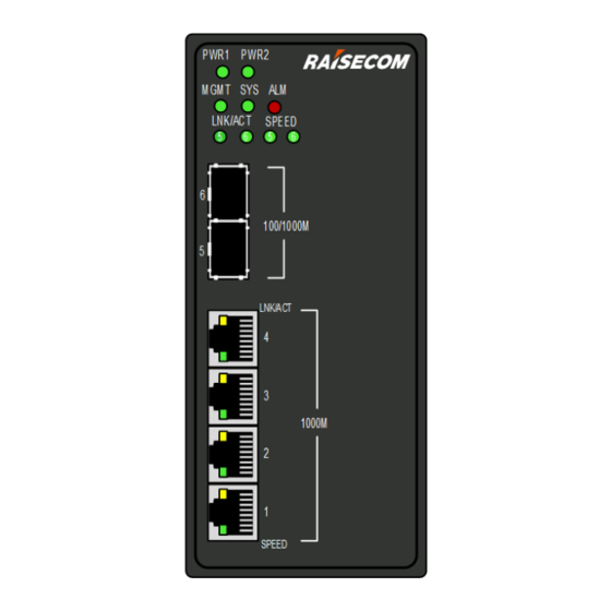
Page 22: Gazelle S1020I-2Gf-4Ge-Gl
Power interface 1 (PWR1 and PWR2) Alarm output interface (ALM) Ground terminal 2.1.3 Gazelle S1020i-2GF-4GE-GL Front appearance of the Gazelle S1020i-2GF-4GE-GL-DCW48 Figure 2-5 shows the front appearance of the Gazelle S1020i-2GF-4GE-GL-DCW48. Raisecom Proprietary and Confidential Copyright © Raisecom Technology Co., Ltd. -
Page 23: Figure 2-5 Front Appearance Of The Gazelle S1020I-2Gf-4Ge-Gl-Dcw48
100/1000M 5–6 electrical interface 100/1000M 5–6: service interface, GE SFP uplink optical interface Top appearance of the Gazelle S1020i-2GF-4GE-GL-DCW48 Figure 2-6 shows the top appearance of the Gazelle S1020i-2GF-4GE-GL-DCW48. Raisecom Proprietary and Confidential Copyright © Raisecom Technology Co., Ltd. -
Page 24: Figure 2-6 Top Appearance Of The Gazelle S1020I-2Gf-4Ge-Gl-Dcw48
Console interface (RJ45) Alarm output interface (ALM) Power interface 2 (PWR2) Power interface 1 (PWR1) Front appearance of the Gazelle S1020i-2GF-4GE-GL-AC Figure 2-7 shows the front appearance of the Gazelle S1020i-2GF-4GE-GL-AC. Raisecom Proprietary and Confidential Copyright © Raisecom Technology Co., Ltd. -
Page 25: Figure 2-7 Front Appearance Of The Gazelle S1020I-2Gf-4Ge-Gl-Ac
100/1000M 5–6 electrical interface 100/1000M 5–6: service interface, GE SFP uplink optical interface Top appearance of the Gazelle S1020i-2GF-4GE-GL-AC Figure 2-8 shows the top appearance of the Gazelle S1020i-2GF-4GE-GL-AC. Raisecom Proprietary and Confidential Copyright © Raisecom Technology Co., Ltd. -
Page 26: Gazelle S1020I-4Gf-8Ge-Gl
Ground terminal RST button Console interface (RJ45) Alarm interface (ALM) Power interface 2.1.4 Gazelle S1020i-4GF-8GE-GL Front appearance of the Gazelle S1020i-4GF-8GE-GL-DCW48 Figure 2-9 shows the front appearance of the Gazelle S1020i-4GF-8GE-GL-DCW48. Raisecom Proprietary and Confidential Copyright © Raisecom Technology Co., Ltd. -
Page 27: Figure 2-9 Front Appearance Of The Gazelle S1020I-4Gf-8Ge-Gl-Dcw48
100/1000M 9–12 electrical interface 100/1000M 9–12: service interface, GE SFP uplink optical interface Top appearance of the Gazelle S1020i-4GF-8GE-GL-DCW48 Figure 2-10 shows the top appearance of the Gazelle S1020i-4GF-8GE-GL-DCW48. Raisecom Proprietary and Confidential Copyright © Raisecom Technology Co., Ltd. -
Page 28: Figure 2-10 Top Appearance Of The Gazelle S1020I-4Gf-8Ge-Gl-Dcw48
Alarm output interface (ALM) Power interface 2 (PWR2) Power interface 1 (PWR1) Ground terminal Front appearance of the Gazelle S1020i-4GF-8GE-GL-AC Figure 2-11 shows the front appearance of the Gazelle S1020i-4GF-8GE-GL-AC. Raisecom Proprietary and Confidential Copyright © Raisecom Technology Co., Ltd. -
Page 29: Figure 2-11 Front Appearance Of The Gazelle S1020I-4Gf-8Ge-Gl-Ac
100/1000M 9–12 downlink electrical interface 100/1000M 9–12: service interface, GE SFP uplink optical interface Top appearance of the Gazelle S1020i-4GF-8GE-GL-AC Figure 2-12 shows the top appearance of the Gazelle S1020i-4GF-8GE-GL-AC. Raisecom Proprietary and Confidential Copyright © Raisecom Technology Co., Ltd. -
Page 30: Interfaces
Table 2-7 lists interface types and usage of the Gazelle S1020i-GL. Table 2-7 Interface types and usage Interface type Description RJ45 10/100/1000BASE-T auto-negotiation electrical interface GE SFP optical interface, supporting the following optical modules: 1000BASE-X 100BASE-FX Raisecom Proprietary and Confidential Copyright © Raisecom Technology Co., Ltd. -
Page 31: Table 2-8 Power And Management Interfaces
DI interface PWH-GL-DC48 input digital signals Gazelle S1020i-4GF-8GE- 5-pin Phoenix connector interface, used to PWH-GL-DC48 input digital signals Gazelle S1020i-2GF-4GE- Gazelle S1020i-4GF-8GE- 3-pin Phoenix connector interface, used to input digital signals Raisecom Proprietary and Confidential Copyright © Raisecom Technology Co., Ltd. -
Page 32: Button
IEEE 802.3-compliant Supported network protocol 2.3.2 10/100/1000BASE-T electrical interface Table 2-11 lists parameters of the 10/100/1000BASE-T electrical interface. Table 2-11 Parameters of the 10/100/1000BASE-T electrical interface Parameter Description Connector type RJ45 Raisecom Proprietary and Confidential Copyright © Raisecom Technology Co., Ltd. -
Page 33: Console Interface
S1020i-4GF-8GE-PWH-GL-DC48 shares the 8-pin Phoenix connector interface with the power supply. The alarm output interface is in form of 3-pin Phoenix connector with spaces of 5.08 mm, as shown in Figure 2-13. Raisecom Proprietary and Confidential Copyright © Raisecom Technology Co., Ltd. -
Page 34: Figure 2-13 Alarm Output Interface 1
Connector type 7.62 mm × 3-pin phoenix terminal Electrical feature Connected/Disconnected Maximum switching voltage 250 VAC/125 VDC Maximum switching current 3 A (250 VAC/30 VDC) Maximum switching capability 90 W Raisecom Proprietary and Confidential Copyright © Raisecom Technology Co., Ltd. -
Page 35: Di Interface
Low level: the input voltage is -30 to +1 V. After login, you can configure the triggering condition of an external alarm to high level or low level in global configuration mode, as described in Table 2-15. Raisecom Proprietary and Confidential Copyright © Raisecom Technology Co., Ltd. -
Page 36: Leds
Green: the system is being started or System status Green working improperly. Blinking green: the system is working properly. Off: the system is being started or working improperly. Raisecom Proprietary and Confidential Copyright © Raisecom Technology Co., Ltd. -
Page 37: Power Supply
The DC-power model supports inputting 48 VDC power. The DC power supply supports dual redundancy input. Support overload protection and reverse polarity protection. Support overvoltage protection and surge protection. Support NMS and electromagnetic relay alarm for battery failure. Raisecom Proprietary and Confidential Copyright © Raisecom Technology Co., Ltd. -
Page 38: Appearance And Interfaces
The DC power interface on the Gazelle S1020i-2GF-4GE-GL and Gazelle S1020i-4GF-8GE- GL is the 2-pin Phoenix connector interface (with spaces of 7.62 mm). Table 2-19 lists interface type and usage of the DC power supply. Raisecom Proprietary and Confidential Copyright © Raisecom Technology Co., Ltd. -
Page 39: Figure 2-19 Appearance Of The Ac Power Interface On The Gazelle S1020I-2Gf-4Ge-Gl-Ac
Table 2-20 interface type and usage of the AC power supply Power module Print Description AC power Ground terminal module (110/220 Connected to the negative pole of the DC voltage or N input VAC) terminal of the AC voltage Raisecom Proprietary and Confidential Copyright © Raisecom Technology Co., Ltd. -
Page 40: Specifications
(dB) e (km) (dBm) USFP- 830–870 -9.5 to -3 > 0 > 9 < -17 0.55 Gb/M-I USFP- 1310 1260–1620 -10 to -3 > -3 > 9 < -21 Gb/S1-I Raisecom Proprietary and Confidential Copyright © Raisecom Technology Co., Ltd. -
Page 41: Cables
> 9.0 < -26 Gb/SS35-I 2.7 Cables 2.7.1 Ground cable Connecting the ground cable properly is an important guarantee for lightning protection, anti-electric shock, and anti-interference. The Gazelle S1020i-GL must be Raisecom Proprietary and Confidential Copyright © Raisecom Technology Co., Ltd. -
Page 42: Figure 2-21 Ground Cable
OT terminal Figure 2-22 OT terminal Inner diameter of Inner diameter of Thickness of soldering lug soldering lug sheath Technical specifications Table 2-24 lists technical specifications of the ground cable. Raisecom Proprietary and Confidential Copyright © Raisecom Technology Co., Ltd. -
Page 43: Table 2-24 Technical Specifications Of The Ground Cable
The ground cable cannot be longer than 30 m and should be as short as possible; otherwise, a ground bar should be used instead. Raisecom Proprietary and Confidential Copyright © Raisecom Technology Co., Ltd. -
Page 44: Console Cable
Figure 2-23 RJ45 Console cable Wiring Figure 2-24 shows PINs and wiring of the Console cable. Figure 2-24 PINs and wiring Technical specifications Table 2-26 lists technical specifications of the Console cable. Raisecom Proprietary and Confidential Copyright © Raisecom Technology Co., Ltd. -
Page 45: Ethernet Cable
Crossover cable: used to connect devices of the same type, such as between PCs, between switches, between routers, or between a PC and a router (they are of the same type) Raisecom Proprietary and Confidential Copyright © Raisecom Technology Co., Ltd. -
Page 46: Figure 2-26 Wiring Of The Straight-Through Cable
Figure 2-26 Wiring of the straight-through cable Crossover cable One RJ45 connector of the 100 Mbit/s crossover cable follows EIA/TIA 568A standard wiring; the other RJ45 connector follows EIA/TIA 568B standard wiring. Raisecom Proprietary and Confidential Copyright © Raisecom Technology Co., Ltd. -
Page 47: Dc Power Cables
Appearance of DC power cable 1 The DC power cable used by the PoE model is composed of the DC power connector and power cable, as shown in Figure 2-28. Raisecom Proprietary and Confidential Copyright © Raisecom Technology Co., Ltd. -
Page 48: Figure 2-28 Dc Power Connector
Appearance of DC power cable 2 The DC power cable used by the non-PoE model is composed of the DC power connector and power cable, as shown in Figure 2-28. Figure 2-29 DC power connector Raisecom Proprietary and Confidential Copyright © Raisecom Technology Co., Ltd. -
Page 49: Ac Power Cable
The AC power cable which meets European standard is composed of the European 3-pin plug and coaxial cable, as shown in Figure 2-30. Figure 2-30 shows the European AC power cable. Figure 2-30 European AC power cable Raisecom Proprietary and Confidential Copyright © Raisecom Technology Co., Ltd. -
Page 50: Figure 2-31 American Ac Power Cable
Cable Outer Black (PVC insulating layer) color Inner White (N), black (L), and yellow strip (E) Conductor Copper core multi-strand power cable 18 AWG (0.75 mm gauge Length 1.5 m Raisecom Proprietary and Confidential Copyright © Raisecom Technology Co., Ltd. -
Page 51: Fiber
Choose a connector suitable for the optical interface. Otherwise, it may increase additional loss of fiber links, reduce transmission quality of services, or even damage the connector and optical interface. Appearance Figure 2-32 shows the appearance of the LC/PC fiber connector. Raisecom Proprietary and Confidential Copyright © Raisecom Technology Co., Ltd. -
Page 52: Figure 2-32 Lc/Pc Fiber Connector
Direction of Peer optical interface relationship optical signals Single-fiber Optical interface <-> Optical interface connection Dual-fiber Optical interface Tx -> Optical interface Rx connection Optical interface Rx <- Optical interface Tx Raisecom Proprietary and Confidential Copyright © Raisecom Technology Co., Ltd. -
Page 53: Technical Specifications
Gazelle S1020i-2GF-4GE-PWH-GL-DC48: 0.8 kg Weight (without guide rail) Gazelle S1020i-2GF-4GE-PWH-GL-DC48: 1.5 kg Gazelle S1020i-2GF-4GE-GL: 0.8 kg Gazelle S1020i-4GF-8GE-GL: 1.1 kg Operating temperature -40 to +75° C Raisecom Proprietary and Confidential Copyright © Raisecom Technology Co., Ltd. -
Page 54: Compliance Standards
Table 3-2 Environmental requirements Parameter Description Air pressure 86–106 kPa Operating temperature (altitude: 0–1800 m) -40 to 75° C Storage temperature -40 to 85° C Operating humidity 5%–95% RH (non-condensing) Raisecom Proprietary and Confidential Copyright © Raisecom Technology Co., Ltd. -
Page 55: Technical Specifications
Radiated Immunity Test (RIT) meets IEC 61000-4-3 level 3 requirements. Electrical Fast Transient (EFT) meets IEC 61000-4-4 level 4 requirements (the Gazelle S1020i-12GF-16GE-GS meets level 3 requirements). Damped oscillatory wave meets IEC 61000-4-18 level 3 requirements. Raisecom Proprietary and Confidential Copyright © Raisecom Technology Co., Ltd. - Page 56 Conducted Immunity (CI) meets IEC 61000-4-6 level 3 requirements. AC voltage dips and short interruptions immunity meets IEC 61000-4-11 requirements. DC voltage dips and short interruptions immunity meets IEC 61000-4-29 requirements. Raisecom Proprietary and Confidential Copyright © Raisecom Technology Co., Ltd.
-
Page 57: Hardware Installation
Gazelle S1020i-GL. If the humidity is high, short circuit may occur. If the room is too dry, a fire may occur. Table 4-1 lists requirements for the operating environment. Raisecom Proprietary and Confidential Copyright © Raisecom Technology Co., Ltd. -
Page 58: Power Supply Conditions
Replacing a card or altering the device may cause extra hazard. Do not do this if you are not a professional technician. To guarantee safety, please contact Raisecom local office or technical support hotline for any questions. Raisecom Proprietary and Confidential... -
Page 59: Installing Device
Step 1 Connect the rail clip to the guide rail, as shown in Figure 4-1. Figure 4-1 Connecting the rail clip to the guide rail Step 2 Press the device to secure it to the guide rail, as shown in Figure 4-2. Raisecom Proprietary and Confidential Copyright © Raisecom Technology Co., Ltd. -
Page 60: Grounding Device
Connect the ground cable as below: Step 1 Loosen the screw of the ground terminal counterclockwise and keep the screw and washer properly, as shown in Figure 4-3. Raisecom Proprietary and Confidential Copyright © Raisecom Technology Co., Ltd. -
Page 61: Connecting Cables
Step 2 Align the Ethernet cable header with the Ethernet interface of the Gazelle S1020i-GL and insert the Ethernet cable into the Ethernet interface gently, as shown in Figure 4-5. Raisecom Proprietary and Confidential Copyright © Raisecom Technology Co., Ltd. -
Page 62: Connecting Fiber
Step 1 Remove the plastic dustproof cover from the optical module and keep it for later use. Step 2 To insert the fiber, align the fiber header with the optical interface and insert the fiber into the optical interface gently. Raisecom Proprietary and Confidential Copyright © Raisecom Technology Co., Ltd. -
Page 63: Connecting Power Cable
Step 2 Insert the power connector into the power interface of the Gazelle S1020i-GL snuggly and tighten the screws at both sides of the connector, as shown in Figure 4-8. Raisecom Proprietary and Confidential Copyright © Raisecom Technology Co., Ltd. -
Page 64: Powering On Device
Table 4-3 Items to be checked after installation Item Method Components are installed properly without loose ends or shedding Check phenomenon. Screws are tightened. Check Cables are correctly connected without loose ends or shedding Check phenomenon. Raisecom Proprietary and Confidential Copyright © Raisecom Technology Co., Ltd. - Page 65 The power cable and the ground cable are properly connected. The Check spring washer is over the flat washer. Space for heat dissipation is reserved around the device. No heavy Check object is laid on the device. Raisecom Proprietary and Confidential Copyright © Raisecom Technology Co., Ltd.
-
Page 66: Management And Maintenance
SSH management SSH is a protocol that provides secure remote login and other secure network services in unsecure networks. When you remotely log in to the Gazelle S1020i-GL in an unsecure Raisecom Proprietary and Confidential Copyright © Raisecom Technology Co., Ltd. -
Page 67: Snmp Mode
Although the Ping feature can test the connectivity, it cannot record all network devices on the route limited by the IP header. Traceroute can be used to test routing information from the source host to the destination host. Raisecom Proprietary and Confidential Copyright © Raisecom Technology Co., Ltd. -
Page 68: Environment Monitoring
5.3 NView NNM System 5.3.1 Functions "Comprehensive Access, Overall Network Management" is a vision that Raisecom has been in pursuit of. The NView NNM system is developed to meet overall and efficient OAM requirements. It is of complete functions, friendly User Interface (UI), and easy operations, which can meet requirements for service activation and daily maintenance. -
Page 69: Features
NView NNM system. 5.3.2 Features The NView NNM system has the following features: Work as a uniform platform for all Raisecom manageable devices. Uniformly manage data network and transport network. Provide strong NE-level management and subnet-level management. -
Page 70: Figure 5-1 Location Of The Nview Nnm System
Raisecom Gazelle S1020i-GL (A) User Manual 5 Management and maintenance Figure 5-1 Location of the NView NNM system Raisecom Proprietary and Confidential Copyright © Raisecom Technology Co., Ltd. -
Page 71: Appendix
(APS) protection line, thus the communication is recovered in a short period. A component installed on both sides of the chassis, used for install the Bracket chassis to the rack. Raisecom Proprietary and Confidential Copyright © Raisecom Technology Co., Ltd. - Page 72 When the link or device on the Ethernet ring fails, services can be (ERPS) quickly switched to the backup line to enable services to be recovered in time. In a communication link, both parties can receive and send data Full duplex concurrently. Raisecom Proprietary and Confidential Copyright © Raisecom Technology Co., Ltd.
- Page 73 Link A protocol used for realizing link dynamic aggregation. The LACPDU is Aggregation used to exchange information with the peer device. Control Protocol Raisecom Proprietary and Confidential Copyright © Raisecom Technology Co., Ltd.
- Page 74 VLAN, all interfaces are isolated from each other. Grounding The cable to connect the device to ground, usually a yellow/green cable coaxial cable. Connecting the grounding cable properly is an important Raisecom Proprietary and Confidential Copyright © Raisecom Technology Co., Ltd.
- Page 75 TCP/IP network. Simple Network Time SNTP is mainly used for synchronizing time of devices in the network. Protocol (SNTP) In this fiber, single-mode optical signals are transmitted. Single-mode Raisecom Proprietary and Confidential Copyright © Raisecom Technology Co., Ltd.
-
Page 76: Acronym And Abbreviations
American National Standards Institute Automatic Protection Switching Address Resolution Protocol Autonomous System ASCII American Standard Code for Information Interchange Autonomous System External Asynchronous Transfer Mode American Wire Gauge Boundary Clock Backup Designated Router Raisecom Proprietary and Confidential Copyright © Raisecom Technology Co., Ltd. - Page 77 Common Spanning Tree Dynamic ARP Inspection Dynamic Bandwidth Allocation Direct Current DHCP Dynamic Host Configuration Protocol DiffServ Differentiated Service Domain Name System Deficit Round Robin Differentiated Services Digital Subscriber Line Raisecom Proprietary and Confidential Copyright © Raisecom Technology Co., Ltd.
- Page 78 Internet Assigned Numbers Authority ICMP Internet Control Message Protocol Internet Explorer International Electro technical Commission IEEE Institute of Electrical and Electronics Engineers IETF Internet Engineering Task Force IGMP Internet Group Management Protocol Raisecom Proprietary and Confidential Copyright © Raisecom Technology Co., Ltd.
- Page 79 MTBF Mean Time Between Failure Maximum Transmission Unit Multicast VLAN Registration Network Management System Network Node Management Network Time Protocol NView NNM NView Network Node Management Operation, Administration, and Management Raisecom Proprietary and Confidential Copyright © Raisecom Technology Co., Ltd.
- Page 80 Quality of Service RADIUS Remote Authentication Dial In User Service RCMP Raisecom Cluster Management Protocol Random Early Detection Relative Humidity Routing Information Protocol RMON Remote Network Monitoring RNDP Raisecom Neighbor Discover Protocol Raisecom Proprietary and Confidential Copyright © Raisecom Technology Co., Ltd.
- Page 81 Terminal Access Controller Access Control System Transparent Clock Transmission Control Protocol TFTP Trivial File Transfer Protocol Type Length Value Type of Service TPID Tag Protocol Identifier Time To Live User Datagram Protocol User-Based Security Model Raisecom Proprietary and Confidential Copyright © Raisecom Technology Co., Ltd.
- Page 82 Raisecom Gazelle S1020i-GL (A) User Manual 6 Appendix VLAN Virtual Local Area Network VRRP Virtual Router Redundancy Protocol Wide Area Network Weight Round Robin Raisecom Proprietary and Confidential Copyright © Raisecom Technology Co., Ltd.
- Page 83 Address Raisecom Building, No. 11, East Area, No. 10 Block, East Xibeiwang Road, Haidian District, Beijing, P.R.China Postal code: 100094 Tel: +86-10-82883305 Fax: 8610-82883056 http://www.raisecom.com Email: export@raisecom.com...
Need help?
Do you have a question about the Gazelle S1020i-GL Series and is the answer not in the manual?
Questions and answers