Table of Contents
Advertisement
Quick Links
Advertisement
Table of Contents

Related Manuals for Nice GEFEN GF-AVIP-MC


Summary of Contents for Nice GEFEN GF-AVIP-MC
- Page 1 AVOIP MATRIX CONTROLLER GF-AVIP-MC User Manual...
-
Page 2: Table Of Contents
Table of Contents Important Safety Instructions . . . . . . . . . . . . . . . . . . . . . . . . . . . . . . . . . . . . . . . . . . . . . . . . 4 Introduction . - Page 3 Table of Contents Auto Assign Process . . . . . . . . . . . . . . . . . . . . . . . . . . . . . . . . . . . . . . . . . . . . . . . . . . . . . . . . . . . .27 Group Settings .
-
Page 4: Important Safety Instructions
Important Safety Instructions Please read all instructions before attempting to unpack, install or operate this equipment and before connecting the power supply. Please keep the following in mind as you unpack and install this equipment: Always follow basic safety precautions to reduce the risk of fire,electrical shock and injury to persons. -
Page 5: Introduction
Introduction This Matrix Controller is a powerful and flexible solution for controlling Gefen compatible Video and KVM over IP based extenders within same network. The user only needs to install this unit into the same local network as the extenders (transmitters and receivers) to easily define and configure channel routing selections(including video, audio and a variety of controller interface types), using the WebGUI. -
Page 6: Applications
Overview Applications • Video/TV wall display and control • Security surveillance and control • Commercial advertising, display and control • Home Theaters with Smart Home Controls • House of Worship/Live Venues • Retail sales and demonstration Package Contents • 1× AVoIP Matrix Controller •... -
Page 7: Combined Mode
Installation The Matrix Controller is designed to manage and control the Gefen family of Video and KVM over IP products in a virtual matrix environment. The Matrix Controller provides two methods of network control: Combined Mode and Separate Mode. Combined Mode This is the default mode and is used when the Matrix Controller is connected to the same switch as the KVM over IP products, degraded because of the large amount of bandwidth required to support video signals on the same switch. -
Page 8: Separate Mode
Installation Separate Mode This mode is used when the KVM over IP products are connected to a separate (dedicated) managed switch. Two CAT-5e (or better) cables will be required to connect the Matrix Controller. If a single switch will be connecting Gefen KVM over IP products in addition to your other network devices. -
Page 9: Rear Panel
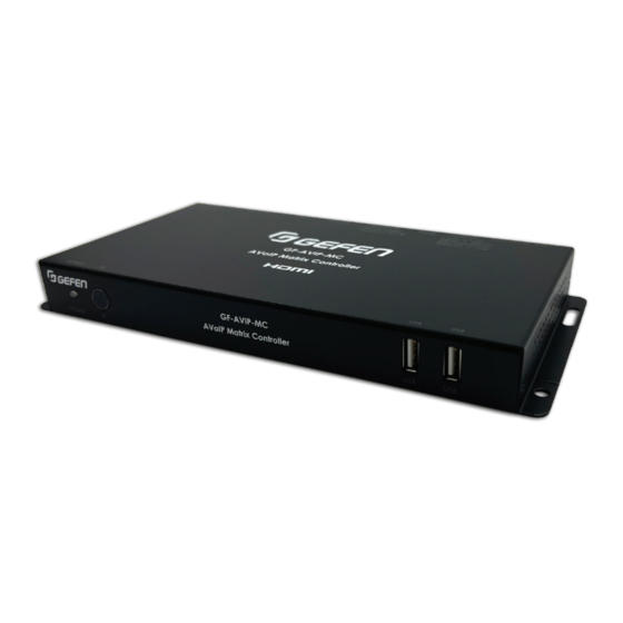
Operation Controls and Functions Front Panel POWER LED: This LED will illuminate to indicate the following: • Green LED solid: Power ON • Green LED flashing: Booting Up • Blue LED solid: Device Ready • LED off: Power OFF/Card Read Error IR Window: Accepts IR signals from the included IR remote for control of this unit only. -
Page 10: Rs-232 Port
Operation Controls and Functions Remote Control PRESET PRESET 1~8: Press any of the 8 buttons to activate the saved preset associated with that number. IR Cable Pinouts CR-183 Infrared Power Ground RS-232 Pinout and Defaults Serial Port Default Settings (RS-232 Port Only) Baud Rate 115200 Data Bits... -
Page 11: Gefen Syner-G Device Discovery
WebGUI Access Methods Gefen Syner-G Device Discovery Download the Gefen Syner-G software at www.gefen.com/gefen-syner-g-software/ Connect the unit and your PC/Laptop to the same active network and run the Gefen Syner-G software. A list of devices connected to the local network will be displayed indicating their current IP address. - Page 12 WebGUI Control Page All functions of this unit are controllable via the built in WebGUI. It's accessed by connecting your web browser to LAN 1’s IP address or by connecting an HDMI display to the unit’s HDMI output and attaching a USB mouse and keyboard to the unit’s USB port. Control via standard HDMI plus USB style touch screens is also supported.
-
Page 13: Virtual On-Screen Keyboard
WebGUI Control Page Virtual On-Screen Keyboard If a USB keyboard for typing is not present, press keyboard icon located on the bottom right of the WebGUI. Clicking on any field will bring up the Virtual On-Screen Keyboard. Monitor & Control Tab This tab provides a graphical representation of all current transmitters, receivers, video walls and video groups. -
Page 14: Video Matrix Routing
WebGUI Control Page Video Matrix Routing NOTE: This tab is fully functional even when the user is logged out with Guest mode enabled. I/O devices must also be assigned to Guest User. • Transmitter Preview: This section displays preview thumbnails from all detected transmitters along with their assigned names. -
Page 15: Video Wall Group Routing
WebGUI Control Page Video Wall Group Routing Select the Video Wall button highlighted below in red. This will display the Video Wall Group Routing Page which allows you to perform drag & drop Video Wall Group Routing. • Group Preview: This section displays preview thumbnails from any selected Video Wall Group. -
Page 16: List View Routing
WebGUI Control Page List View Routing Select the Table List View Icon highlighted in red to display the List View Routing page. This page allows the user to select multiple or all receivers to be routed to a selected Transmitter. Mute/Unmute, Mask and Block functions are configurable on this page. NOTE: This tab is fully functional even when the user is logged out with Guest mode enabled. -
Page 17: Transmitter Pane
WebGUI Control Page Transmitter Pane • Search: This global field allows searching a Transmitter device by any keyword. The Channel, Device and Descriptions columns consists of Search fields also allowing to filter by keyword. • Reset Search: This button will clear the Transmitter search field. •... -
Page 18: List View Video Wall Group Routing
WebGUI Control Page List View Video Wall Group Routing This page allows the user to select a single, multiple, or all Video Wall groups to be routed to a selected Transmitter. Mute/Unmute, Mask and Block functions and Save to Preset are configurable on this page. •... -
Page 19: Save To Preset
WebGUI Control Page Save to Preset This allows to save the current routing state to a Preset. Press the Save to Preset button. NOTE: This function is only available to logged in Users including Guest. A prompt will appear to save to Preset. •... -
Page 20: Independent Routing Tab
WebGUI Control Page Independent Routing Tab This page allows for independently routing I/O signals for Video, Audio, IR, RS-232, or USB from any Transmitter to any Receiver. By default, the routing these I/O signals will follow video of the routed Transmitter to the Receiver unit. To select a fixed route for a Receiver, use the drop down box of the desired I/O signal and select a Transmitter. -
Page 21: Video Wall Group Tab
WebGUI Control Page Video Wall Group Tab The Video Wall Group page allows the user to design, edit and manipulate a video wall system created using multiple receiver units connected to identical displays. The bezel and video size of the displays being used, as well as the horizontal and vertical monitor count is defined here. - Page 22 WebGUI Control Page • Video Wall Bezel: This section is used to define the physical dimensions of each display being used in the video wall. Accurate measurements are needed of the monitor’s outer frame (OW, OH) and the video screen (VW, VH). The measurements may be made using any unit of measurement (inches, mm, cm, etc.) as long as ALL measurements in the same wall are made using the exact same units and the numbers are integers.
-
Page 23: I/O Tab - Transmitter Page
WebGUI Control Page I/O Tab - Transmitter Page I/O Tab - Receiver Page... - Page 24 WebGUI Control Page • Discover Device: Only used for systems utilizing legacy EXT-CU-LAN systems where Gefen’s Discovery Protocol has been disabled for all Transmitters/ Receivers. Utilize this function to broadcast a UDP message to turn on Discovery Protocol which is required for GF-AVIP-MC to operate properly. •...
-
Page 25: For Transmitter
WebGUI Control Page • Video Info: Click this button to display the Video Information including Resolution, Color Depth, HDCP and limited EDID information. Note: When this button is highlighted in red, it indicates that no signal has been detected. For Transmitter For Receiver NOTE: Hovering your mouse over the Info button will provide quick information without the need of accessing the Video Info function. - Page 26 WebGUI Control Page • Device Settings: Click on the Device Settings button to configure the Transmitter or Receiver Settings. Press the Save button and perform a device reboot to apply settings. See System Command options to perform a device reboot. NOTE: Functions will vary depending on the Gefen Video and KVM over IP models used.
-
Page 27: Auto Assign Process
WebGUI Control Page » RS232 Settings: Click the RS-232 Settings button to access the RS- 232 settings of the device. Press the Save button and perform a device reboot to apply settings. » USB Settings: Click the USB Settings button to access the USB settings of the device. -
Page 28: Group Settings
WebGUI Control Page Group Settings This page provides a way to define a group of displays that will all receive the same routed source when used in Presets or from the Monitor & Control tab. Receivers can be assigned to a Group by simply performing drag & drop of any or all Receivers. Saved Groups will appear in the Routing pages as a routable item in the Receiver pane. -
Page 29: Preset Settings
WebGUI Control Page Preset Settings This page allows to Create, Edit and Delete Presets. Saved presets can be recalled within the Preset Recall tab. • Add Preset: Create a new Preset. Click on this button to add a new Preset. •... -
Page 30: Edid Management
WebGUI Control Page • Transmitter: Click on the drop down menu select the Transmitter to route from. • Receiver/Group: Click on the drop down menu select the Receiver, Group, or Video Wall Group to route to. • Order: Assigns the order of each Command to be executed when multiple commands are created within a preset. -
Page 31: I/O Trigger
WebGUI Control Page I/O Trigger Assign a preset to each of the Trigger inputs which can be activated by an external trigger. Time • Sync with NTP Server: Allows to Sync time from a configured NTP server. The default setting is set to Enable. •... -
Page 32: Schedule
WebGUI Control Page • NTP Server: Enter NTP Server URL. Default URL is time.google.com. • Timezone: Select Timezone • Daylight: Enable or Disable Daylight Savings Time. Schedule • Add Schedule: Creates a new schedule. Click on this button to add a new schedule. -
Page 33: Repeat Mode
WebGUI Control Page Repeat Mode This configures a schedule Repeat based on starting Activation Date, Time Interval and End Date. Press the Save Schedule button to apply changes. • Activation Date: Starting date and time to trigger a Schedule. • Time Interval Day: Enter the number of days to trigger a Preset relative to the Activation Date. -
Page 34: Weekly Mode
WebGUI Control Page Weekly Mode This configures a Schedule on a Weekly basis. Select the Activation date, time and Days (Monday ~ Sunday) to trigger a Preset. Press the Save Schedule button to apply changes. User Management This page allows you to Create, Edit and Delete User accounts. Each account can be assigned with any Transmitter or Receiver with a simple drag &... -
Page 35: Access Levels
WebGUI Control Page Access Levels Admin – Default Username and Password for Admin is Full Access admin/admin User - Up to 8 maximum of users are supported Same as Admin but excludes: EDID management, Time, User Management, IO Trigger, Network Settings, Factory Reset, Factory Reset ALL TX/RX, Auto-Assign, Discovery Device, Firmware Upgrade (Controller and KVM over IP), Save/Upload Config... -
Page 36: Firmware Upgrade
WebGUI Control Page • Reset all RXs: Click this button to factory reset all Receivers. • Reboot System: Click this button to reboot the controller. • Reboot all TXs: Click this button to reboot all Transmitters. • Reboot all RXs: Click this button to reboot all Receivers. •... -
Page 37: Avoip Batch Update
WebGUI Control Page Upgrade All (Transmitter/Receiver) To update all Transmitters and Receivers, click the Choose File button to open the file selection window and then select an appropriate batch firmware update file in a "*.7z" format. (For ex. AVoIP_3.17.7z). The update process may take more than 10 minutes to complete. -
Page 38: Network Settings
WebGUI Control Page Network Settings This tab provides access to system configuration options including IP configuration for both LAN ports, Discovery Protocol settings, TCP and UDP configurations. • LAN1 & LAN2 Pane: The IP mode for each LAN port (DHCP, Static IP, or Auto IP), IP address, netmask and gateway can be set here. -
Page 39: Discovery Protocol Settings
WebGUI Control Page • Gateway: Enter gateway address of the managed switch. Press Save and Reboot to apply changes. This field is only available if the Mode is set to Static. The default Gateway for LAN1 is 192.168.1.1. Discovery Protocol Settings •... -
Page 40: Tcp/Telnet Settings
Menu System Summary TCP/Telnet Settings • TCP Access: Click these buttons to enable or disable TCP access. • Telnet Port: Enter the Telnet listening port in this field. • Login Message on Connect: Click these buttons to show or hide the Telnet welcome message at the beginning of each Telnet session. -
Page 41: Udp Configuration
Menu System Summary UDP Configuration • Configure the desired control system for UDP. • Click the Network Settings tab within the web interface and do the following. » Click the Enabled button next to UDP Access. » Enter the UDP listening port in the UDP Port field. The default UDP listening port is 50007. -
Page 42: General Udp Commands
General UDP Commands Help #HELP Prints all available TCP/UDP commands to the screen. Syntax #HELP PARAM1(OPTIONAL) Parameters PARAM1 - ANY TCP/UDP COMMAND (NO '#') Example #HELP SET_IP_MODE SET THE IP MODE TO DHCP, STATIC, OR AUTO IP Example Feedback #SET_IP_MODE PARAM1 PARAM1 = 0 - 2 (0 = STATIC;... - Page 43 General UDP Commands Network Settings (cont.) #SET_LAN_MODE Set LAN mode to combined or separate. Syntax #SET_LAN_MODE PARAM1 PARAM1 = 1 ~ 2 Parameters 1 - COMBINED 2 - SEPARATE Example #SET_LAN_MODE 2 LAN_MODE 2 Example Feedback REBOOT UNIT TO APPLY CHANGES #GET_LAN_MODE Get LAN mode status.
-
Page 44: General Udp Commands
General UDP Commands Network Settings (cont.) #SET_IP_ADDRESS Set the IP address. Syntax #SET_IP_ADDRESS PARAM1 PARAM1 = 1 ~ 2 1 - LAN1 (CONTROL PORT) 2 - LAN2 (VIDEO PORT) Parameters PARAM2 = XXX.XXX.XXX.XXX XXX - 0 ~ 255 Example #SET_IP_ADDRESS 1 192.168.1.72 Example Feedback IP_ADDRESS 1 192.168.1.72 #GET_IP_ADDRESS... - Page 45 General UDP Commands Network Settings (cont.) #SET_GATEWAY Set the Gateway address. Syntax #SET_GATEWAY PARAM1 PARAM1 = 1 ~ 2 1 - LAN1 (CONTROL PORT) 2 - LAN2 (VIDEO PORT) Parameters PARAM2 = XXX.XXX.XXX.XXX XXX - 0 ~ 255 Example #SET_GATEWAY 1 192.168.1.1 Example Feedback GATEWAY 1 192.168.1.1 #GET_GATEWAY...
- Page 46 General UDP Commands Network Settings (cont.) #SET_TELNET_PORT Set the Telnet Communication port. Syntax #SET_TELNET_PORT PARAM1 Parameters PARAM1 = 0 ~ 65535 Example #SET_TELNET_PORT 23 Example Feedback TELNET_PORT 23 #GET_TELNET_PORT Get the current Telnet Communication port. Syntax Parameters #GET_TELNET_PORT Example Example Feedback TELNET_PORT 23 #SET_UDP_ACCESS Enable/disable UDP access.
- Page 47 General UDP Commands Network Settings (cont.) #GET_UDP_PORT Get the current UDP communication port. Syntax Parameters #GET_UDP_PORT Example Example Feedback UDP_PORT 50007 #SET_UDP_R_ACCESS Enable/disable remote UDP access. Syntax #SET_UDP_R_ACCESS PARAM1 PARAM1 = 0 ~ 1 Parameters 0 - DISABLED 1 - ENABLED Example #SET_UDP_R_ACCESS 1 Example Feedback...
-
Page 48: Discovery Settings
General UDP Commands Network Settings (cont.) #SET_REMOTE_UDP_PORT Set the remote_UDP communication port. Syntax #SET_REMOTE_UDP_PORT PARAM1 Parameters PARAM1 = 0 ~ 65535 Example #SET_REMOTE_UDP_PORT 50008 Example Feedback REMOTE_UDP_IP 192.168.1.29 #GET_REMOTE_UDP_PORT Get the current remote UDP communication port. Syntax Parameters #GET_REMOTE_UDP_PORT Example Example Feedback REMOTE_UDP_IP 192.168.1.29 Discovery Settings... -
Page 49: System Settings
General UDP Commands Network Settings (cont.) #GET_DEVICE_DESC Get the Discovery Description. Syntax Parameters #GET_DEVICE_DESC Example Example Feedback DEVICE DESCRIPTION IS SET TO DEVICE #SET_SHOWME Enable/disable the Discovery 'SHOW ME' feature. Syntax #SET_SHOWME PARAM1 PARAM1 = 0 ~ 1 Parameters 0 - DISABLED 1 - ENABLED #SET_SHOWME 1 Example... -
Page 50: Input Status
General UDP Commands System Settings (cont.) #REBOOT Reboot the unit. Syntax Parameters #REBOOT Example Example Feedback UNIT WILL REBOOT SHORTLY Input Status #GETS_INPUT_SIGNAL Get active signal status of one or all inputs. Syntax #GETS_INPUT_SIGNAL PARAM1 PARAM1 = 0, 1 ~ N Parameters 0 - ALL INPUTS 1 ~ N = TX CHANNEL... - Page 51 General UDP Commands Input Status (cont.) #GETS_INPUT_TIMING Get timing of HDMI input. Syntax #GETS_INPUT_TIMING PARAM1 PARAM1 = 0, 1 ~ N Parameters 0 - ALL INPUTS 1 ~ N - TX CHANNEL #GETS_INPUT_TIMING 0 #GETS_INPUT_TIMING 1 RESPONSE = AAAAxBBBBCDD Example AAAA - HORIZONTAL RESOLUTION BBBB - VERTICAL RESOLUTION C - PROGRESSIVE/INTERLACE...
- Page 52 General UDP Commands Output Status (cont.) #GETS_OUTPUT_HDCP Get HDCP status of one or all outputs. Syntax #GETS_OUTPUT_HDCP PARAM1 PARAM1 = 0, 1 ~ N Parameters 0 - ALL RECEIVERS 1 ~ N = RX ID #GETS_OUTPUT_HDCP 0 #GETS_OUTPUT_HDCP 1 RESPONSE = A,U,F Example A = ACTIVE U = UNENCRYPTED...
-
Page 53: Routing Udp Commands
Routing UDP Commands #REBOOT_TX Syntax #REBOOT_TX PARAM1 PARAM1 = 0, 1 ~ N Parameters 0 - ALL INPUTS 1 ~ N - TX CHANNEL #REBOOT_RX Syntax #REBOOT_RX PARAM1 PARAM1 = 0, 1 ~ N Parameters 0 - ALL INPUTS 1 ~ N - RX ID Route transmitter to a specific receiver, group, or videowall group. - Page 54 Routing UDP Commands Routing (cont.) Description Independently route audio. Syntax A PARAM1 A PARAM1 PARAM2 (OPTIONAL PARAM3 ~ PARAM#) PARAM1 = F, 1 - N Parameters F - FOLLOW CURRENT ROUTED TRANSMITTER CHANNEL 1 ~ N = FIXED ROUTE TO SPECIFIC TX CHANNEL PARAM2 = 1 - N (RX ID) Example A 1 2...
- Page 55 Routing UDP Commands Routing (cont.) Description Independently route IR. Syntax I PARAM1 PARAM2 (OPTIONAL PARAM3 ~ PARAM#) PARAM1 = F, 1 - N F = FOLLOW CURRENT ROUTED TRANSMITTER CHANNEL 1 ~ N = FIXED ROUTE TO SPECIFIC TX CHANNEL Parameters PARAM2 = 0, 1 ~ N 0 - ALL RECEIVERS...
- Page 56 Routing UDP Commands Routing (cont.) #SET_TX_MUTE Mute/Unmute audio Syntax #SET_TX_MUTE PARAM1 PARAM2 PARAM1 = 0, 1 ~ N 0 - ALL TRANSMITTERS 1 ~ N - (TX CHANNEL) Parameters PARAM1 = 0 - 1 0 - UNMUTE AUDIO 1 - MUTE AUDIO Example #SET_TX_MUTE 0 1;...
- Page 57 Routing UDP Commands Routing (cont.) #GET_RX_MUTE Get the current status of audio mute. Syntax #GET_RX_MUTE PARAM1 PARAM1 = 0, 1 ~ N Parameters 0 - ALL RECEIVERS 1 ~ N - (RX ID) Example #GET_RX_MUTE 0; #GET_RX_MUTE 1 RX_MUTE 1 1 2 1 3 1 Example Feedback RX_MUTE 1 0 #SET_MASK...
- Page 58 Routing UDP Commands Routing (cont.) #SET_BLOCK Enable/Disable video block feature Syntax #SET_MASK PARAM1 PARAM2 PARAM1 = 0, 1 ~ N 0 - ALL TRANSMITTERS 1 ~ N - (TX CHANNEL) Parameters PARAM2 = 0 - 1 0 - DISABLE 1 - ENABLE Example #SET_BLOCK 0;...
-
Page 59: Preset Udp Commands
Preset UDP Commands #SET_VW Set videowall layout. Syntax #SET_VW PARAM1 PARAM2 PARAM1 = 1 ~ N (VIDEOWALL ID) PARAM2 = 0 - 1 Parameters 0 - DISABLE 1 - ENABLE Example #SET_VW 2 1 Example Feedback VW 2 1 #GET_VW Get videowall status. -
Page 60: Connection Diagram
Connection Diagram... -
Page 61: Technical Specifications
Technical Specifications HDMI Output Resolution 1920×1080@60Hz Output Port 1×HDMI (Type-A) 1×IR Extender (3 .5mm) 1×RS-232 (3-pin Terminal Block) 8×Trigger (10-pin Terminal Block) Control Ports 2×LAN (RJ-45) 2×USB 2 .0 (Type A) Service Port 1x MicroSD Slot Reserved Port 1×Control (5-pin Terminal Block) IR Frequency 38kHz Baud Rate... -
Page 62: Warranty And Return Policy
Warranty and Return Policy Nice North America warrants the equipment it manufactures to be free from defects in material and workmanship . If Gefen equipment fails because of such defects and Nice North America is notified within the specified warranty period* from the documented** date of purchase, Nice North America will, at its option, repair or replace the equipment, provided that the equipment has not been subjected to mechanical, electrical, or other abuse or modifications . -
Page 63: Notes
Notes... - Page 64 All trademarks are the property of their respective owners. All features and specifications are subject to change without notice. Gefen and Nice North America LLC reserve the right to make changes in the hardware, packaging and any accompanying documentation without prior notice. AVoIP Matrix Controller is a trademark of Gefen, LLC.