Table of Contents
Advertisement
Nice Swing Gate
Actuator
Vehicular Swing Gate Actuator
and programming and controls for 1050 Control Board
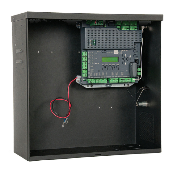
CBOX with 1050 control board
Programming for 1050 Control Board - page 21
These operators use the 1050 control board: 1551 LA, TITAN12L1 and 3501
See separate installation and reference manuals for TITAN12L/12L1 (912L-1)
actuator and 3501 (ABOX35) arm
Revision 4.0.0.0_03-2019
Part # 10001150
816 actuator installation instructions
Model 1551
1050 Control Board
816 Actuator
Advertisement
Table of Contents


Need help?
Do you have a question about the 1551 and is the answer not in the manual?
Questions and answers