Advertisement
Table of Contents
- 1 Table of Contents
- 2 General Rules of Safety
- 3 Preparation for Installation
- 4 Control and Connection Elements
- 5 Mechanical Limit Switch Setting
- 6 Digital Limit Switch Setting
- 7 Motor Connection Cable
- 8 Terminal Diagram
- 9 Electronic Boards - Overview
- 10 Technical Data
- 11 Declaration of Conformity
- Download this manual
Advertisement
Table of Contents

Related Manuals for Nice UST1K-1.1kW


Summary of Contents for Nice UST1K-1.1kW
- Page 1 UST1K UST1K-1.1kW UST1K-2.2kW UST1K-5.5kW Automatic industrial door control unit Instructions and information for installation and use The entire instruction manual is made up of instructions for using the motor and its control unit. English – 1...
-
Page 2: Table Of Contents
TABLE OF CONTENTS GENERAL RULES OF SAFETY ..................PREPARATION FOR INSTALLATION ................3 CONTROL AND CONNECTION ELEMENTS ..............4 MECHANICAL LIMIT SWITCH SETTING ................. 7 DIGITAL LIMIT SWITCH SETTING ................... 9 MOTOR CONNECTION CABLE ................12-14 TERMINAL DIAGRAM ....................15-16 ELECTRONIC BOARDS - OVERVIEW ..............17-18 TECHNICAL DATA ...................... -
Page 3: General Rules Of Safety
Do not start installation if you have any doubts of any kind fulfi l the current regulations and directives (e.g. DIN 1986, EN 12050). and, if necessary, contact the Nice Assistance Service. He is responsible for drawing up the technical documentation of the entire plant to be supplied together with the plant. -
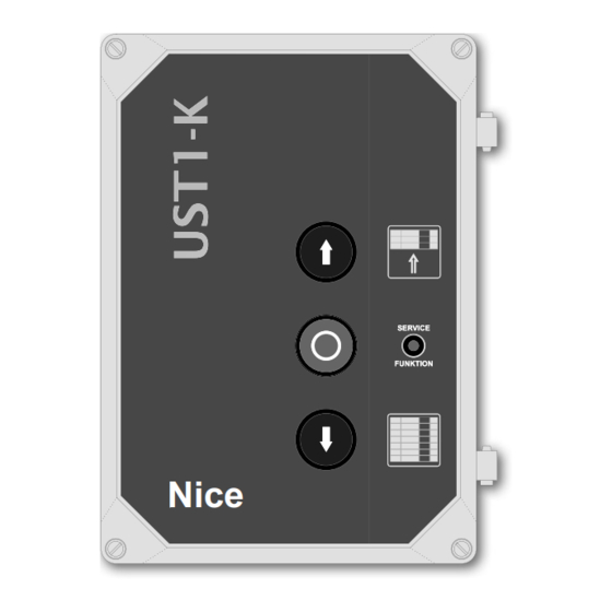
Page 4: Control And Connection Elements
In this case it is possible to remove the Schuko plug during assembly. It is possible to connect other control elements for control from the outside, a triple button for example. UST1K-1.1kW UST1K- starting A switch with a cable coming down from the ceiling, installed inside or outside, controls the door in the OPEN-STOP-CLOSE function. - Page 5 Connection of the transmitters of the OPEN, STOP, Connection of an optical sensitive edge (fi g.5) The optical sensitive edge is structured so that a beam of light is CLOSE controls (fi g.4) interrupted along its entire length when it is activated. A receiver is For controlling from the outside, it is possible to connect a triple connected to its end so the sensitive edge can be controlled along switch to terminal block X4 in the UST1K control unit.
- Page 6 Photo Connection of the remote control (radio module) It is possible to connect the Nice OXI or OXIFM receiver of the OPERA series to the 10 PIN slot (J38). To this regard, it is necessary that the side with the programming/ LED button faces the internal side of the housing.
-
Page 7: Mechanical Limit Switch Setting
Tighten the fi xing screw A. MECHANICAL LIMIT SWITCH SETTING To get accurate adjustment, use the screw B. Move the door into the desired OPENING position. Set the contact cam 1 E (green) so the limit switch is enabled. Mechanical limit switch setting Tighten the fi... - Page 8 UST1K-2.2kW board connection 20μF blue yellow blue yellow/green black brown Input 1x220V phase Input 1x220V neutral 16μF yellow/green Additional board UST1K-1.1kW board connection 20μF blue yellow blue yellow/green black brown Input 1x220V phase Input 1x220V neutral 16μF yellow/green 8 – English...
-
Page 9: Digital Limit Switch Setting
ASSEMBLY - SETTING SETTINGS - FINAL POSITIONS (also see fi g. 12-14) Then put the DIP switch 1 on "OFF". Now Setting of the fi nal positions the lower bar remains lit, while the central bar Set the switch DIP 1 on "ON". The upper fl... - Page 10 Electronic limit switches Electronic limit switches A type B type Wires 1, 2 and 3 ve-pole Control unit ultiple connection ca a ble apter ontrol unit nnection Six-pole plug Six-pole plug Control unit connection cable Control unit connection cable Control station Wire Contact with zero...
- Page 11 SETTINGS OF THE AUTOMATIC FUNCTIONS Operation functions DIP 4 = OFF In normal operating conditions, the The door blocks and reaches the upper fi nal position if the status of the door and/or the number sensitive edge is enabled during the downward movement. of the error present are shown on the display.
-
Page 12: Motor Connection Cable
CONNECTION CABLE FOR GEARMOTORS EQUIPPED WITH ELECTRONIC LIMIT SWITCH - WITH SCREENING 12 – English... - Page 13 CONNECTION CABLE FOR GEARMOTORS EQUIPPED WITH ELECTRONIC LIMIT SWITCH - WITHOUT SCREENING English – 13...
- Page 14 CONNECTION CABLE FOR GEARMOTORS EQUIPPED WITH ELECTRONIC LIMIT SWITCH - WITH SCREENING 14 – English...
-
Page 15: Terminal Diagram
Wiring diagram UST1K-1.1kW LED2 LED3 LED1 LED4 LED6 LED5 LED8 LED7 LED9 LED10 TRANSFORMER PROTECTION PROTECTION English – 15... - Page 16 Wiring diagram UST1K - starting from 2.2kW Antenna screw OPENING setting T2 setting button Radio coupling Plug connection CLOSING setting terminal button for cover LED button J1 U-bolt LED 2 DIP switch Coupling terminal of Display contact barrier + door half height Button T1 manual transmitter setting Coupling terminal...
-
Page 17: Electronic Boards - Overview
Electronic board UST1K-1.1kW T2 setting Radio coupling CLOSING DIP switch Antenna screw OPENING button setting button terminal setting button Display Coupling terminal of contact barrier Button T1 + door half height manual transmitter setting Coupling terminal S2 rotary selector Brake relay... - Page 18 Electronic board UST1K - 2.2kW and 5.5kW Antenna screw T2 setting button Radio coupling OPENING setting CLOSING setting Plug connection terminal button for cover LED button J1 U-bolt LED 2 DIP switch Coupling terminal of Display contact barrier + door half height Button T1 manual transmitter setting Coupling terminal...
-
Page 19: Technical Data
• All of the technical characteristics indicated refer to a temperature of 20°C (± 5°C). • Nice reserves the right to introduce all modifi cations to the product it deems necessary at any time, however keeping the functions and intended use unaltered. -
Page 20: Declaration Of Conformity
Note - The content of this declaration corresponds to the declaration at the last available version of the document fi led in the offi ces of Nice S.p.A. prior to the printing of this manual. This text has been adapted to meet editorial requirements. A copy of the original declaration may be requested from Nice S.p.a.
Need help?
Do you have a question about the UST1K-1.1kW and is the answer not in the manual?
Questions and answers