Table of Contents
Advertisement
Quick Links
Nice Swing Gate
Actuator
Vehicular Swing Gate Actuator
CBOX with 936 control board
912L
Programming & controls, connections and safety
information provided in the 1550/1551 manuals in CBOX
Revision 8.0 December, 2018
Part #10001700
TITAN12L
936 Control Board
TITAN12L1
1050 Control Board
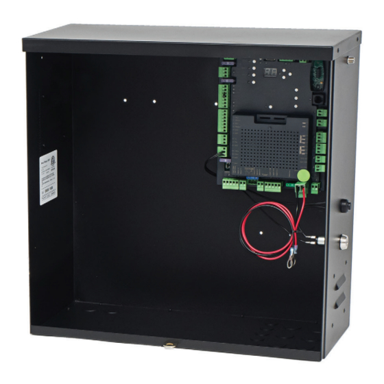
CBOX with 1050 control board
Advertisement
Table of Contents

Related Manuals for Nice TITAN12L


Summary of Contents for Nice TITAN12L
- Page 1 Nice Swing Gate Actuator TITAN12L 936 Control Board Vehicular Swing Gate Actuator TITAN12L1 1050 Control Board CBOX with 936 control board CBOX with 1050 control board 912L Programming & controls, connections and safety information provided in the 1550/1551 manuals in CBOX Revision 8.0 December, 2018...
-
Page 3: Table Of Contents
FIGURE 10 - 7 Manual Release Re-engage Troubleshooting 26-27 10.5 - TITAN12L/12L1 Actuator Wiring Appendix - French Translations 28-31 FIGURE 10 - 8 Manual Release Handle FIGURE 10 - 9 Wire Harness Insertion FIGURE 10 - 10 TITAN12L/12L1 Actuator Wiring www.hysecurity.com... -
Page 4: Overview
600 lb for a 20 ft leaf or 1000 lb for an 8 ft leaf. Operator has a key lockable manual release, easily accessible limit switch settings and is easy to maintain or repair in-the-fi eld. The TITAN12L/12L1 gives dealers, installers and homeowners the ability to take control of their access and security systems. - Page 5 Easy setup with 7-segment LEDs and dedicated in connector is provided for direct installation of buttons. a Nice-brand receiver which can be associated Setup and learning stored in onboard memory. with up to 1000 remote controls. Connectors for ...
- Page 6 Built-in regulator to keep the battery charged connector is provided for direct installation of a (either through solar or Main DC power). Nice-brand receiver which can be controlled by up Socket for plug-in Nice receiver. to 1000 transmitters. A recessed RJ-11 jack offers a ...
-
Page 7: General Safety Information
2. General Safety Information 1.8 The installation of this product is not a “do- it-yourself” project. A qualifi ed gate operator A gate operator is only a component in a gate installation company should be contacted system. The other parts of the gate system to install the gate operator to ensure a safe can include the gate, the external entrapment and reliable installation. - Page 8 Some operators are restricted in their usage application. All Nice USA operators are approved for use in all four UL325 Usage Classes. Appropriate Usage Classes are shown in the Specifi cations.
- Page 9 Guarding is supplied for exposed rollers. on the side of the gate on which the placard is installed. e. When utilizing a Nice 936 board and 1050 board and 8 sensors may be connected. 2.10 For gate operators utilizing a non-contact 2.4 The operator is intended for installation only...
-
Page 10: Use Of Vehicle Detectors
4. Gate Construction and Safety 2.11 For a gate operator utilizing a contact sensor (Edge): Gate construction plays a very important role in a. One or more contact sensors shall be ensuring the safety of any automated gate system. located where the risk of entrapment or The standard for gate construction is ASTM F2200. - Page 11 4.1.8 Gates shall be designed, constructed and 4.2.1.3 A gap, measured in the horizontal installed such that their movement shall not plane parallel to the roadway, between be initiated by gravity when an automatic a fixed stationary object nearest the operator is disconnected.
-
Page 12: Maintenance Of Gate Systems
5. Maintenance of Gate Systems 4.3 Vehicular Horizontal Swing Gates 4.3.1 The following provisions shall apply to To keep your automated gate system performing Class I, Class II, and Class III horizontal swing both safely and reliably it is important to ensure gates: that the components of that system are functioning properly. -
Page 13: Entrapment Protection
6. Entrapment Protection a. The gap between the bottom of a moving gate and the ground is greater than 4 in. The UL325 standard for gate operators requires (101.6 mm) and less than 16 in. (406 mm); or a minimum of two independent entrapment b. -
Page 14: Compatible External Sensors
Entrapment System (IES) (UL325 Type A) that Only the following external sensors have been monitors the force on the gate during travel. evaluated and tested with Nice gate systems and This system protects in both the open and are approved to be used for protection against... -
Page 15: 936 Circuit Board Layout
8 - 936 CIRCUIT BOARD LAYOUT LEARN BUTTON DUAL 7 SEGMENT STATUS DISPLAY WINDOW PROGRAM BUTTONS ACCESSORY POWER OUTPUT AND PROGRAMMABLE INPUT A ACCESSORY PROGRAM MENU POWER OUTPUT CONTROL BUTTONS AND STEP INPUT GATE OPERATION CONTROL BUTTONS INPUTS ACCESSORY POWER OUTPUTS OUTPUTS ACCESSORY... -
Page 16: 1050 Circuit Board Layout
9 - 1050 CIRCUIT BOARD LAYOUT Power Input Motor Output Connections Connections SOLAR P. BATTERY MAIN DC POWER 30A FUSE MOTOR MOTOR 2 SERIES 1050 UL325 Compliant Monitored Safety Devices(s) required. Accessory Output OXI/A Receiver Connections BlueBus Connection Primary / Secondary Connection Earth Ground Accessory Input Connections... -
Page 17: Installation Procedures
10 - INSTALLATION PROCEDURES 10.1 - Pivot Arm Installation IMPORTANT - Never weld parts to the gate or posts when the operator circuit board is powered. Doing so may damage the board beyond repair. PULL TO OPEN INSTALLATION - Location of Pivot Point The following instructions provide up to 105°... -
Page 18: Push To Open Installation
10 - INSTALLATION PROCEDURES (CONT.) 10.2 - Push to Open Installation PIVOT ARM INSTALLATION - Location of Pivot Point Measurements are taken from the center of pivot of the gate hinge. The pivot arm needs to be securely mounted to the hinge post or equivalent mounting surface. It is recommended to weld the pivot arm to a metal post. -
Page 19: Manual Release/Manual Operation
10 - INSTALLATION PROCEDURES (CONT.) 10.4 - Manual Release / Manual Operation MANUAL RELEASE DISENGAGE 1. Lift rubber key cover, insert key into lock, and rotate 90° clockwise. 2. Lift handle 3. Actuator is now Disengaged (manual operation is possible). NOTE: Manual operation may be prevented if the actuator is fully retracted. -
Page 20: Titan12L/12L1 Actuator Wiring
The connections are on the top of the actuator behind the limit assembly. Terminal block for harness connections FIGURE 10 - 9 WIRE HARNESS INSERTION Connect the wiring to the actuator terminal block as shown. FIGURE 10 - 10 TITAN12L/12L1 ACTUATOR WIRING www.hysecurity.com... -
Page 21: 936 Control Board Wiring
Connect the Nice TITAN actuator cable to the 5-pin connector as shown below. These connections enable the connector as shown below. These connections enable the Nice TITAN limit switch and smart sensor inputs into the Nice TITAN limit switch and smart sensor inputs into the gate controller. - Page 22 Connect the Nice TITAN actuator cable to the 5-pin connector as shown below. These connections enable the connector as shown below. These connections enable the Nice TITAN limit switch and smart sensor inputs into the Nice TITAN limit switch and smart sensor inputs into the gate controller.
-
Page 23: Limit Switch Adjustment
10 - INSTALLATION PROCEDURES (CONT.) 10.8 - Limit Switch Adjustment 16. Turn the knob controlling the linear motion of the extend limit cog BEFORE continuing with this section, make sure to (blue) to bring it into contact with the limit switch. If this is done have the MANUAL for the control box specific to this correctly you will see: installation in hand. -
Page 24: General Layout And Safety Access
11 - GENERAL LAYOUT AND SAFETY ACCESS Possible Entrapment Zones - Typical Installation Diagram Utilizing Loop Sensors and Photocells Safety Loop (for vehicle Detection Only) 4’ Min. from closed gate 4’ Min. from closed gate Loop (Shadow) Close Close 4’ Min. from open gate Direction Direction Safety Loop... -
Page 25: Accessories And Sensors
12 - ACCESSORIES AND SENSORS EXTERNAL ENTRAPMENT PROTECTION Non-contact and contact sensors must be installed individually or in combination with each other to provide complete external entrapment protection. Care should be exercised to reduce the risk of nuisance tripping, such as when a vehicle trips the sensor while the gate is still moving, and one or more non-contact sensors shall be located where the risk of entrapment or obstruction exists, such as the perimeter reachable by a moving gate or barrier. -
Page 26: Inspection And Operation
13 - INSPECTION AND OPERATION 14 - EMERGENCY VEHICLE ACCESS Proper inspection of all equipment is required to ensure continuous The automatic vehicular gate system must be designed to allow functionality, safety and to ensure reliable operation in all weather access to emergency vehicles under different operating conditions. -
Page 27: Maintenance Schedule
15 - MAINTENANCE SCHEDULE Table 2 COMPLETE BASIC Alarm Activate the (inherent) reverse system by blocking the gate with a solid object. The gate should reverse momentarily then stop. Restart the gate and block again with a solid object. The gate ... - Page 28 16 - TROUBLESHOOTING (CONT.) Table 4: 1050 Board Display Read Out and Troubleshooting DISPLAY REASON POSSIBLE SOLUTION Dynamic M1 Actuated connected to Motor Check for obstruction in gate path or degraded gate hardware. 1 has a brief current spike and tripped Type A sensor.
-
Page 29: Appendix - French Translations
17 - Appendix - French Translations FRENCH TRANSLATIONS The following French translations provided below are found in the Safety Section located at the beginning of the manual. English French INSTRUCTIONS DE SÉCURITÉ IMPORTANTES IMPORTANT SAFETY INSTRUCTIONS AVERTISSEMENT – Pour réduire les risques de WARNING –... - Page 30 17 - Appendix - French Translations (CONT.) English French Install the gate operator only when: N’installez l’ouvre-barrière que si : The operator is appropriate for the construction l’ouvre-barrière est approprié pour la structure et of the gate and the usage Class of the gate, la classe d’utilisation de la barrière;...
- Page 31 17 - Appendix - French Translations (CONT.) English French Les commandes destinées à l’activation par Controls intended for user activation must be l’utilisateur doivent être situées à au moins 1,83 located at least 1.83 m (6 ft) away from any m (6 pi) des pièces mobiles de la barrière et à...
- Page 32 17 - Appendix - French Translations (CONT.) English French A hardwired contact sensor shall be located and Un capteur de contact doit être installé et câblé its wiring arranged so that the communication de sorte à éviter que la communication entre between the sensor and the gate operator is not le capteur et l’ouvrebarrière soit gênée par des subjected to mechanical damage.
- Page 33 www.hysecurity.com...
- Page 34 www.hysecurity.com...
- Page 35 www.hysecurity.com...
- Page 36 Contact us Nice 6705 S. 209th St., Suite 101 Kent, WA 98032-2327 Ph. +1.253.867.3700 Fax +1.253.867.3702 www.hysecurity.com www.facebook.com/hsgateoperators www.hysecurity.com...
Need help?
Do you have a question about the TITAN12L and is the answer not in the manual?
Questions and answers