Table of Contents
Advertisement
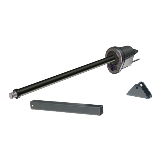
816 LA
Apollo 1500 / 1550 / 1551
Linear actuator
EN
- Installation and reference manual
IMPORTANT - These instructions apply only to the 816 actuator. Control
box installation/operation is described in a separate control box manual.
www.ApolloGateOpeners.com | (800) 878-7829 | Sales@ApolloGateOpeners.com
Advertisement
Table of Contents

Related Manuals for Nice Apollo 816 LA


Summary of Contents for Nice Apollo 816 LA
- Page 1 816 LA Apollo 1500 / 1550 / 1551 Linear actuator - Installation and reference manual IMPORTANT - These instructions apply only to the 816 actuator. Control box installation/operation is described in a separate control box manual. www.ApolloGateOpeners.com | (800) 878-7829 | Sales@ApolloGateOpeners.com...
-
Page 2: Table Of Contents
Apollo 816 LA Linear Actuator Installation Reference Manual TABLE OF CONTENTS SECTION 1: APOLLO 816 ACTUATOR OVERVIEW....3 SECTION 2: INSTALLATION SAFETY..........4 SECTION 3: TOOLS NEEDED FOR INSTALLATION....4 SECTION 4: 816 ACTUATOR MECHANICAL INSTALLATION..5 SECTION 5: 816 TO CONTROL BOARD CONNECTIONS..13 5.1 816 to 936 CONTROLLER WIRING......14... -
Page 3: Section 1: Apollo 816 Actuator Overview
SECTION 1: APOLLO 816 ACTUATOR OVERVIEW Congratulations on selecting a Nice Apollo 816 LA linear actuator for your gate opener system. With proper selection, system design, installation, and maintenance this actuator should provide years of reliable operation. This manual covers ONLY the installation of the Apollo 816 LA linear actuator. -
Page 4: Section 2: Installation Safety
Be aware of all moving parts and avoid proximity to any pinch points. ’ SECTION 3: TOOLS NEEDED Below is a list of tools necessary for installation of the Apollo 816 LA actuator: • Welder (for pivot arm) unless optional bolt-on pivot arm (P/N 446) is used. •... - Page 5 Apollo 816 LA Linear Actuator Installation Reference Manual SECTION 4: 816 ACTUATOR INSTALLATION INSTALL PIVOT ARM TO GATE: PULL-TO-OPEN NOTICE 1. Securely mount the pivot arm to the hinge post (Fig-1A). Welding is much preferred 2. If necessary, cut pivot arm for correct placement of the actuator but Nice offers an optional mounting hole.
- Page 6 Apollo 816 LA Linear Actuator Installation Reference Manual INSTALL PIVOT ARM TO GATE: PUSH-TO-OPEN 1. Securely mount the pivot arm to the hinge post (Fig-1B). NOTICE 2. If necessary, cut pivot arm for correct placement of the actuator Welding is much preferred but mounting hole.
- Page 7 Apollo 816 LA Linear Actuator Installation Reference Manual MOUNT ACTUATOR TO PIVOT ARM 1. Mount the actuator to the pivot arm as shown (IMAGE 2-1). Note that the washer goes above the actuator flange. 2. Tighten the lock nut to prevent movement or shifting when the actuator is running. This will also prevent excessive “bounce”...
- Page 8 Apollo 816 LA Linear Actuator Installation Reference Manual AFFIX GATE BRACKET TO ACTUATOR ARM 1. If security is of the utmost importance then the bracket may be connected to the actuator arm using 1/2” x 3” bolt, washer, and lock nut (Fig-3A).
- Page 9 Apollo 816 LA Linear Actuator Installation Reference Manual 3: AFFIX GATE BRACKET TO ACTUATOR ARM (CONT.) 1/2”x 3” BOLT 1/2” WASHER GATE BRACKET ACTUATOR 1/2” LOCK NUT Fig-3C: Gate Bracket with Bolt, Washer, Nut HITCH PIN GATE BRACKET ACTUATOR R-CLIP Fig-3D: Gate Bracket with Hitch Pin And R-Clip www.ApolloGateOpeners.com | (800) 878-7829 | Sales@ApolloGateOpeners.com...
- Page 10 Apollo 816 LA Linear Actuator Installation Reference Manual POSITION GATE BRACKET ON GATE 1. Place gate in: a) OPEN position for PULL-TO-OPEN configuration (Fig-4A). b) CLOSED position for PUSH-TO-OPEN configurations (Fig-4B). 2. With actuator arm fully retracted, rotate entire actuator on the pivot arm around until the gate bracket attached to the actuator is positioned on a supporting structure of gate.
- Page 11 Apollo 816 LA Linear Actuator Installation Reference Manual AFFIX GATE BRACKET TO GATE 1. Weld the gate bracket to the gate supporting structure (IMAGE 5-1) or use supplied 3/8” bolts and nuts from kit (IMAGE 5-2). CAUTION Never weld parts to the gate or posts when the control board...
- Page 12 Apollo 816 LA Linear Actuator Installation Reference Manual RUN ACTUATOR CABLE(S) TO CONTROL BOX 1. Run the cable of the actuator closest to the control box through a hole (with rubber grommet) drilled in the bottom on the control box. If necessary, entry may be made elsewhere on the control box.
-
Page 13: 816 To 936 Controller Wiring
Apollo 816 LA Linear Actuator Installation Reference Manual 816 - CONTROLLER WIRING SECTION 5: REMOVE CONNECTOR NOTICE The actuator cable comes with a connector and battery lugs (Fig-7A), which must be cut off before wiring to the controller. BATTERY LUGS ACTUATOR CONNECTOR Fig-7A: 816 Existing Connector &... - Page 14 SlowDown SlowDown +12V +12V Input Input Apollo 816 LA Linear Actuator Receiver AutoClose AutoClose Installation Reference Manual Options Options 5.1 936 WIRING Open Open Open Open Close Close Input +12V a F/W Jumper Learn Stop Stop Force +12V Stop Close...
- Page 15 Apollo 816 LA Linear Actuator Fire Fire Installation Reference Manual +12V +12V 936 WIRING: PUSH-TO-OPEN Input Input Alarm 1. Locate MOTOR 1 and MOTOR 2 connectors on 936 board per IMAGE 8. 2. If single gate, wire MOTOR 1 as shown.
- Page 16 Apollo 816 LA Linear Actuator Installation Reference Manual 5.2 1050 WIRING MOTOR 2 MOTOR 1 NOTICE If a gate moves in opposite d i r e c t i o n f r o m w h a t i s expected, reverse the motor power lead wiring (red &...
- Page 17 Apollo 816 LA Linear Actuator Installation Reference Manual 1050 WIRING: PUSH-TO-OPEN 1. Locate MOTOR 1 and MOTOR 2 connectors on 1050 board per IMAGE 9. 2. If single gate, wire MOTOR 1 as shown. 3. If dual gate, wire MOTOR 1 and MOTOR 2 as shown.
- Page 18 Apollo 816 LA Linear Actuator Installation Reference Manual 5.3 MERCURY 310 WIRING NOTICE Mercury 310 motor wiring is the same for push-to- open and pull-to-open gate installations. MOTOR 1 MOTOR 2 Fig-10: Apollo 816 Extend and Retract Limit Screws MERCURY 310 WIRING 1.
-
Page 19: Section 6: Setting 816 Open/Close Limits
Apollo 816 LA Linear Actuator Installation Reference Manual SECTION 6: SETTING 816 OPEN/CLOSE LIMITS IMPORTANT! These instructions are ONLY for adjusting the location of limit sensors inside the Apollo 816 actuator. After setting these limits, see the “Learn Limits” procedure in the appropriate controller manual for instructions on how to enable the controller to “learn”... -
Page 20: 816 Limits: 936 Or 1050
Apollo 816 LA Linear Actuator Installation Reference Manual 6.1 816 LIMITS: 936 AND 1050 IMPORTANT! These instructions are ONLY for adjusting the location of limit sensors inside the Apollo 816 actuator. After setting these limits, see the “Learn Limits” procedure in the appropriate controller manual for instructions on how to enable the controller to “learn”... - Page 21 Apollo 816 LA Linear Actuator Installation Reference Manual SCENARIO A Limit LEDs do not light when gate moves to desired gate position: Limit is set to beyond the desired gate position. Extend Less Extended Arm: Rotate Extend screw CW to (CW) extend less.
-
Page 22: 816 Limits: Mercury 310
Apollo 816 LA Linear Actuator Installation Reference Manual 6.2 816 LIMITS: MERCURY 310 IMPORTANT! These instructions are ONLY for adjusting the location of limit sensors inside the Apollo 816 actuator. After setting these limits, see the “Learn Limits” procedure in the appropriate controller manual for instructions on how to enable the controller to “learn”... -
Page 23: Section 7: Part Drawings
Apollo 816 LA Linear Actuator Installation Reference Manual SECTION 7: PART DRAWINGS www.ApolloGateOpeners.com | (800) 878-7829 | Sales@ApolloGateOpeners.com... - Page 24 Apollo 816 LA Linear Actuator Installation Reference Manual www.ApolloGateOpeners.com | (800) 878-7829 | Sales@ApolloGateOpeners.com...
- Page 25 Apollo 816 LA Linear Actuator Installation Reference Manual www.ApolloGateOpeners.com | (800) 878-7829 | Sales@ApolloGateOpeners.com...
-
Page 26: Section 8: Warranty
This warranty will be interpreted, construed, and enforced in all respects in the name plate of a manufacturer other than HySecurity or Nice and they are not a accordance with the laws of the State of Washington, without reference to its part of the base model.
Need help?
Do you have a question about the Apollo 816 LA and is the answer not in the manual?
Questions and answers