
Related Manuals for Daikin VAM Series


Summary of Contents for Daikin VAM Series
- Page 1 EDMMT712101 Heat Reclaim Ventilator (VAM Series) VAM 150HVE/HVLT VAM 250HVE/HVLT VAM 350HVE/HVLT VAM 500HVE/HVLT VAM 650HVE/HVLT VAM 800HVE/HVLT VAM1000HVE/HVLT VAM1500HVE/HVLT VAM2000HVE/HVLT 50 / 60 Hz...
-
Page 3: Table Of Contents
EDMMT712101 Heat Reclaim Ventilator (VAM Series) 1. Product Introduction ................3 1.1 Nomenclature ..................10 1.2 Structure....................11 1.3 Features ....................12 1.4 Selection Procedures ................16 2. Control System..................22 3. Specification..................79 4. Dimensions ...................86 5. Wiring Diagram ..................89 6. Electric Characteristics................91 7. Fan Performance ..................92 8. - Page 4 EDMMT712101 17.6 Precautions for Design and Installation..........181 Table of Contents...
-
Page 5: Heat Reclaim Ventilator (Vam Series)
EDMMT712101 Product Introduction 1. Product Introduction Good quality air for every day Controlling the necessary elements will improve the quality of ventilation. In case of natural ventilation (Class 3) Conditioned air will be Air Conditioner released through windows and exhaust fan Insects, dust and noise enter from outside Room temperature... - Page 6 Product Introduction EDMMT712101 A i r f l o w C o n t r o l Class 1 Ventilation Class 2 Ventilation Class 3 Ventilation Both supply air and exhaust air are controlled by mechanical System that uses mechanical System that uses natural ventilation ventilation in order to achieve for supply air and mechanical...
- Page 7 EDMMT712101 Product Introduction V e n t i l a t i o n v o l u m e c o n t r o l w i t h C O s e n s o r i n t e r l o c k i n g D u r i n g i n c r e a s e i n C O l e v e l i n t h e r o o m , v e n t i l a t i o n a i r v o l u m e w i l l b e i n c r e a s e d t o h a v e h i g h e r a i r e x c h a n g e i n o r d e r t o r e d u c e...
- Page 8 . The system can be interlocked with Daikin air conditioners to provide energy saving ventilation solution for various situation.
- Page 9 Daikin dealer I m p r o v e d i n s t a l l a t i o n m e t h o d 1.
- Page 10 Product Introduction EDMMT712101 A p p l i c a t i o n E x a m p l e Ventilation related points to be taken into note during designing stage. Restaurant Re g ard le ss o f th e ind u stry , th e ca us e of dif ficu lty in Problem opening doors may be due...
- Page 11 EDMMT712101 Product Introduction Air Treatment Equipment A i r f l o w r a t e c o n t r o l w i t h CO s e n s o r The CO sensor controls airflow rate so that it best matches the changes of CO level in the room.
-
Page 12: Nomenclature
Product Introduction EDMMT712101 Nomenclature V A M H VE Ventilation Mounted type Airflow rate (m / h) Major design category (Design category for EC application) Power supply VE: 1 phase, 220–240 / 220 V, 50 / 60 Hz VL: 1 phase, 220 V, 60 Hz Standard symbol T: Taiwan Blank: General countries... -
Page 13: Structure
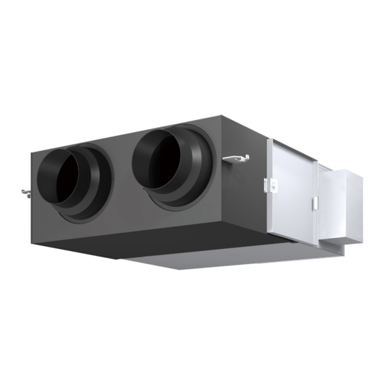
EDMMT712101 Product Introduction Structure VAM150HVE / VAM250HVE / VAM350HVE / VAM500HVE / VAM650HVE / VAM800HVE / VAM1000HVE VAM150HVLT / VAM250HVLT / VAM350HVLT / VAM500HVLT / VAM650HVLT / VAM800HVLT / VAM1000HVLT (Outdoor air) Heat exchange element [Fresh air from outdoor] Duct connector (Exhaust air) [Exhaust air to outdoor] (Supply air) -
Page 14: Features
Interlocked Operation with VRV (SkyAir) 1. Simultaneous ON / OFF with the indoor unit with the indoor unit remote controller. 2. Heat Reclaim Ventilator (VAM series) independent operation during air conditioning off season with the indoor unit remote controller. 3. Automatic ventilation mode changeover: Auto / Heat Recovery / Bypass 4. - Page 15 Product Introduction 1.3.2 Energy Saving Heat Reclaim Ventilator (VAM series) recovers the thermal energy during cooling / heating operation of air conditioner. Heat Reclaim Ventilator (VAM series) reduces the By heat recovery operation cooling / heating load drastically and enhances the heating / cooling efficiency.
- Page 16 Application Offices, etc. Hospitals, Nursing homes, etc. Portion of Normal Heat Reclaim Ventilator Air supply exhaust operation ventilation fan Heat Reclaim (VAM series) Air exhaust Ventilator (VAM series) Air supply Sick room Floor area Air exhaust Example Portion of fresh up operation ex.
- Page 17 EDMMT712101 Product Introduction 1.3.5 The Operation is Available when the Outdoor Air Temperature is Down to -15°C (Operation when the outdoor air temperature becomes lower than -10°C) When the outdoor air suction temperature becomes lower than -10°C, the unit is changed to intermittent operation to prevent freezing of the heat exchanger element and dew condensation within the unit.
-
Page 18: Selection Procedures
Product Introduction EDMMT712101 Selection Procedures Various methods are used to calculate the required ventilating airflow rate according to CO generated by inhabitants in a room, waste gas generated by use of fire, and other conditions of a room. Here are 2 patterns of calculating methods. 1.4.1 Based on Breathing Zones The outdoor airflow required in the breathing zone (Vbz) of the occupiable space or spaces in a ventilation zone shall be not less... - Page 19 EDMMT712101 Product Introduction TABLE 1 Minimum Ventilation Rates in Breathing Zone (This table is not valid in isolation; it must be used in conjunction with the accompanying notes.) Default Values People Outdoor Area Outdoor Air Rate Air Rate Occupant Density Combined Outdoor Occupancy Notes...
- Page 20 Product Introduction EDMMT712101 TABLE 1 Minimum Ventilation Rates in Breathing Zone (Continued) (This table is not valid in isolation; it must be used in conjunction with the accompanying notes.) Default Values People Outdoor Area Outdoor Air Rate Air Rate Occupant Density Combined Outdoor Occupancy Notes...
- Page 21 EDMMT712101 Product Introduction TABLE 1 Minimum Ventilation Rates in Breathing Zone (Continued) (This table is not valid in isolation; it must be used in conjunction with the accompanying notes.) Default Values People Outdoor Area Outdoor Air Rate Air Rate Occupant Density Combined Outdoor Occupancy Notes...
- Page 22 Product Introduction EDMMT712101 TABLE 1 Minimum Ventilation Rates in Breathing Zone (Continued) (This table is not valid in isolation; it must be used in conjunction with the accompanying notes.) Default Values People Outdoor Area Outdoor Air Rate Air Rate Occupant Density Combined Outdoor Occupancy Notes...
- Page 23 EDMMT712101 Product Introduction 1.4.2 Based on Residential Building Room Size A) Ventilation Rate. A mechanical exhaust system, supply system, or combination thereof, shall be installed to operate for each dwelling unit to provide continuous dwelling-unit ventilation with outdoor air at a rate not less than specified in Section A-1. A-1) Total Ventilation Rate.
-
Page 24: Control System
Control System EDMMT712101 2. Control System System overview ● Field settings are required. Control method Control equipment Functions Purpose / Application System overview ※1 ※2 Heat Reclaim Ventilator Unit Basic example of use (Hand-operated control — — — 〇 〇 〇... - Page 25 EDMMT712101 Control System Centralized Transmission Line Networks Max. cable length: 1000m or below / Max. wiring length: 2000m or below Multidrop network Bus network Star (Cascade) network Notes) 1. Bus network and star network cannot be combined with each other. 2.
- Page 26 Control System EDMMT712101 Introduction to Major Connection Terminals Terminal Function Descriptions Notes) 1. All the system configurations in this section use commercial multi air conditioners (building multi) as an Power terminal example. The same controls can be performed when the air conditioners are replaced with the SkyAir series.
- Page 27 EDMMT712101 Control System Setting Descriptions and Setting Numbers Mode Reset Setting position (Note 4) Setting descriptions Switch (Note 3) Group No. setting for centralized control 00 (30) — — — — — — — — — — — — — —...
- Page 28 Control System EDMMT712101 Note) 1. The factory default setting position is displayed in the frame. 2. Setting items with two-digit setting switch numbers (10 or more) can be set only from remote controller BRC1E63 or later. 3. The settings are applied to the entire group, but if the mode number inside the ( ) is selected, the setting can be applied to individual units.
- Page 29 EDMMT712101 Control System Basic Patterns System overview Independent operation system Individual control Control by 2 remote controllers Group control Basic example of use Perform fine operation of Heat Reclaim Ventilator Connected a remote controller to each Heat Control multiple Heat Reclaim Ventilator Units Unit and display at hand or at a distance.
- Page 30 Control System EDMMT712101 Air conditioner interlock system (commercial multi air conditioners (building multi) /SkyAir) 1 group interlocking control 1 group interlocking control Interlocking control of 2 or more groups (standard system) (duct direct connection system) Perform energy-saving interlocked control of 2 or more Perform energy-saving interlocked control groups of Heat Reclaim Ventilator Unit and indoor unit of Heat Reclaim Ventilator Unit using the...
- Page 31 EDMMT712101 Control System Centralized management system ※1 Collective / individual management Zone Management [Unified ON / OFF controller] The start/stop of 16 groups can be controlled with one controller. Up to 8 Zone management is possible whereby the same control can be units can be connected in one system.
- Page 32 Control System EDMMT712101 Independent operation system Individual control Purpose • Function Basic use of remote controller Perform operations and display output of one unit of Heat Reclaim Ventilator Unit using one remote controller. Points for using a remote controller ...
- Page 33 EDMMT712101 Control System Control by 2 remote controllers Purpose • Function One unit (or one group) of Heat Reclaim Ventilator Unit Perform fine operation of Heat Reclaim Ventilator Unit and display output, at hand or at a distance, by using two remote controllers. ...
- Page 34 Control System EDMMT712101 Air conditioner interlock system with commercial multi air conditioners (multi for buildings)/SkyAir 1 group interlocking control (standard system) Purpose • Function Energy-saving interlocked operation can be performed using the remote controller for indoor unit of commercial multi air conditioners (multi for buildings)/SkyAir.
- Page 35 EDMMT712101 Control System 1 group interlocking control (direct duct connection system) Purpose • Function Performs energy-saving interlocked control by duct connection of Heat Reclaim Ventilator Unit and indoor unit of commercial multi air conditioners (multi for buildings)/SkyAir that can take in fresh air. ...
- Page 36 Control System EDMMT712101 Interlocking control of 2 or more groups Purpose • Function Performs energy-saving interlocked control with 2 or more groups of commercial multi air conditioners (multi for buildings)/SkyAir. Heat Reclaim Ventilator Unit also operates if any of the air conditioners is in operation. During intermediate periods, independent operation of Heat Reclaim Ventilator Unit can be performed.
- Page 37 EDMMT712101 Control System Centralized management system Batch/individual management [Unified ON/OFF controller (DCS301BA62)] Purpose • Function Batch start/stop of 16 groups or start/stop of individual unit can be performed with one controller. Up to 128 groups, which consist of 16 groups x 8 units of Unified ON/OFF controllers, can be connected on a single centralized transmission line (within a system).
- Page 38 Control System EDMMT712101 Zone management [Central remote controller (DCS302CA61)] Purpose • Function Up to 64 groups of Heat Reclaim Ventilator Unit and indoor units can be connected to make individual/batch start/stop available on a zone basis together with various monitoring. ※Energy-saving interlocking control and independent ventilation operation is possible within the same zone.
- Page 39 EDMMT712101 Control System Examples of Wiring and System Design Error A remote controller needs to be connected to remote controller transmission line. When a remote controller transmission line is connected, be sure to connect a remote controller on the transmission line. Reason Signal communications on remote controller transmission line starts with remote controller.
- Page 40 Control System EDMMT712101 Application Patterns Additional Functions Start/Stop by Power Supply [Heat Reclaim Ventilator Unit] Purpose • Functions Heat Reclaim Ventilator Unit is started/stopped by turning the power breaker ON/OFF. This function is available only in independent system. (In interlocked system and centralized management system, a transmission error is displayed due to power OFF) POINT ...
- Page 41 EDMMT712101 Control System Extraction of operation/error indication (KRP1C18) [Heat Reclaim Ventilator Unit → Indicator (locally procured)] Purpose • Functions Extracts operation indication or error indication of one Heat Reclaim Ventilator Unit. Example of control wiring Extraction of operation indication Extraction of error indication Power supply for indicators Power supply for indicators P1 P2...
- Page 42 Control System EDMMT712101 Extraction of various signals Purpose • Functions Extracts various signals (operation indication, error indication, filter sign, of one Heat Reclaim Ventilator Unit. Example of control wiring Contact capacity NO VOLTAGE A-CONTACT 240 VA or below Power supply Output A Output B P1 P2...
- Page 43 EDMMT712101 Control System Fresh-Up (Pre Vent) Operation [Heat Reclaim Ventilator Unit] Purpose • Functions Performs excessive air supply operation to prevent backflow of odor by interlocking with a local (toilet/kitchen) ventilation fan. (The balance between air supply and exhaust airflow is set to air supply > exhaust air.) The exhaust fresh-up operation can also be set to prevent the spread of contaminated indoor air and moisture to other rooms by keeping the room under negative pressure.
- Page 44 Control System EDMMT712101 Selection of External Input Terminal Function Purpose • Functions Switches functions by contact signal input to (J1, JC) terminals. POINT Fresh-up ON/OFF and changeover of fresh-up ......Reset Input Operation Functions Behaviors (Pre Vent) Position contact operation lamp operation mode can be done.
- Page 45 EDMMT712101 Control System Distant control by external input Purpose • Functions Heat Reclaim Ventilator Unit can be started/stopped remotely by non-voltage constant a contact signal. POINT During group control, Heat Reclaim Ventilator Unit starts/stops together with the entire group if it is connected to any one of the units in the group.
- Page 46 Control System EDMMT712101 Operations by External Input Purpose • Functions Operates Heat Reclaim Ventilator Unit by external contact signal. Note) If this function is used, the use of standard remote controller, interlocking with air conditioner, and control by centralized equipment or external input terminal cannot be performed. POINT ...
- Page 47 EDMMT712101 Control System Interlock with External Damper Purpose • Functions The printed circuit board of the Heat Reclaim Ventilator Unit outputs the signal to open and close electric damper in conjunction with the operation of Heat Reclaim Ventilator Unit. Installation image Electric damper Heat Reclaim Ventilator Unit (locally procured)
- Page 48 Control System EDMMT712101 Pre-cooling/Pre-heating operation Purpose • Functions This is an energy saving function to reduce the ventilation load at the start of air conditioner by delaying the operation of Heat Reclaim Ventilator Unit during the startup operation of air conditioner in early morning. POINT Operating conditions ...
- Page 49 EDMMT712101 Control System Automatic nighttime free cooling function Purpose • Functions When the air conditioners are switched off at night, the room temperature raised by OA equipment is cooled by ventilation to reduce the cooling load when the air conditioner is switched on the next morning POINT ...
- Page 50 Control System EDMMT712101 Stand-Alone Nighttime Free Cooling Function Purpose • Functions When the air conditioners are switched off at night, the room temperature raised by OA equipment is cooled by ventilation to reduce the cooling load when the air conditioner is switched on the next morning POINT ...
- Page 51 EDMMT712101 Control System 24-hour ventilation operation Purpose • Functions In properties where constant (24-hour) ventilation is required, it is possible to operate the unit at a low airflow rate even when no one is in the room at night. POINT ...
- Page 52 Control System EDMMT712101 24-Hour Ventilation Operation (continued) Example of control wiring Switching “Enable/Disable” for 24-hour ventilation function by external input Transmission wiring is up to 50m. (Contact on site) P1 P2 Heat Reclaim Ventilator Unit 24-hour ventilation Contact on site Specifications for external contact Disabled Short circuit...
- Page 53 EDMMT712101 Control System Fan Control by CO Sensor Purpose • Functions This is the function to automatically change airflow rate of Heat Reclaim Ventilator Unit according to the changes in CO concentration when the ventilation rate “Auto” is selected. POINT ...
- Page 54 Control System EDMMT712101 Airflow Rate Increase during Bypass Mode Purpose • Functions Unit operation Enhances outside air cooling effect during the intermediate When switched to bypass mode during “Auto” ventilation periods by increasing the airflow rate of bypass mode. mode, the airflow rate is automatically increased. POINT When a CO sensor is installed, this function is disabled as the...
- Page 55 Use nonflammable duct for the electric heater. Be sure to keep 2 m or more between the heater and Heat Reclaim Ventilator (VAM series) for safety. For the Heat Reclaim Ventilator (VAM series), use a different power supply from that of the electric heater and install a circuit breaker for each. Electric heater capacity formula Heat capacity P (kW) = 0.29 Airflow rate Temp.
- Page 56 Control System EDMMT712101 C: 3P343420-1E VAM-HVE/HVLT Series...
- Page 57 EDMMT712101 Control System Automatic Ventilation Mode Control by Humidity Sensor (Optional Accessory) Purpose • Functions This is a function to enhance energy efficiency and comfort through automatic switching of ventilation mode, which is realized by performing control in combination of standard temperature sensor and additional indoor (RA) • outdoor (OA) humidity sensor. Energy-saving ventilation mode Reduces load on air conditioner by calculating indoor (RA) and outdoor (OA) enthalpy to automatically determine ventilation mode.
- Page 58 Control System EDMMT712101 Control to Prevent High Humidity Outside Air from Entering by Using Humidity Sensor (Optional Accessory) Purpose • Functions This is a function to detect high humidity outside air and reduce ventilation rate (lower the notch) by adding an outdoor (OA) humidity sensor.
- Page 59 EDMMT712101 Control System Auto cut-off control Purpose • Functions This is a function to prevent Heat Reclaim Ventilator Unit from operating for a long period of time due to failure to turn it off. Unit operation Judgement criteria for auto cut-off control 1.
- Page 60 Control System EDMMT712101 Sensor data sharing function Purpose • Functions By sharing data from CO sensor and humidity sensor among the units within the group, even the units having no sensor can also use the control functions that use each sensor. POINT ...
- Page 61 EDMMT712101 Control System Centralized management system Batch/Individual operation [Central remote controller <DCS302CA61>] Purpose • Functions Able to perform batch or individual start/stop without zone management (while retaining 64 zone setting) Unified ON/OFF controller, etc. can also be combined. Ventilation rate and mode can be switched with DCS302CA61. POINT ...
- Page 62 Control System EDMMT712101 Batch operation [Schedule timer <DST301BA61>] Purpose • Functions Weekly schedule management of up to 128 units is possible by batch start/stop. Central remote controller, etc. can also be combined. POINT S etting of group number for centralized control is not required. ...
- Page 63 EDMMT712101 Control System Batch operation [Wiring adapter for electrical appendices <KRP2A Series>] Purpose • Functions Batch start/stop of up to 64 groups is possible. (To perform individual operation, use central remote controller and Unified ON/OFF controller.) POINT W iring adapter for electrical appendices can be incorporated into one of the units connected by the centralized transmission line. ...
- Page 64 Control System EDMMT712101 Central remote controller + Unified ON/OFF controller An easy-to-use selection needs to be made to RC1……………Central remote controller (DCS302CA61) RC2……………Unified ON/OFF controller (DCS301B1) suit the user’s purpose. RSA, RSB…… Remote controller for air conditioner R1~4………… Remote controller for Heat Reclaim Ventilator Unit System overview (Use BRC1H62 or BRC1E63 for VAM-H.) Central remote controller...
- Page 65 EDMMT712101 Control System Interlocked operation with other air conditioners Interlocked operation with other air conditioners Purpose • Functions Operates Heat Reclaim Ventilator Unit in an interlocked way using operation command of air conditioner fan. In case of no direct duct connection, independent operation is performed individually by remote controller for Heat Reclaim Ventilator Unit.
- Page 66 Control System EDMMT712101 Adapter for wiring < KRP1C18> This optional accessory is used to extract operation indications. Names and Functions of Parts /RyH /RyC /RyF X1M/TeS1 To connector X9A on the indoor printed circuit board (A1P) YC Y1 COMPRESSOR Terminal for external output (allowable current 20mA~1.2A) See page 39 for changeover of adapter for wiring output.
- Page 67 EDMMT712101 Control System ① Ambient conditions Be sure to check the following ambient conditions before using the Heat Reclaim Ventilator unit. ※ However, it must be a normal living space with air-conditioned temperature and humidity. Therefore, it cannot be used in a refrigerator with a large temperature difference or in an extremely cooled condition, even if the values are within the range below.
- Page 68 Control System EDMMT712101 Usage conditions [General information] Do not install in the following locations or areas. • Places where damages due to salt, hot spring or the like occur • Places that are prone to fogs (the moisture resistant type can be used within the range of [①...
- Page 69 EDMMT712101 Control System Intake air conditions that require measures against condensation on the right, and when the high temperature air B is heat exchanged and the air condition exceeds the saturation curve as shown in C, condensation or frost may form Absolute humidity on the heat exchange element.
- Page 70 Control System EDMMT712101 Operation sound (noise reduction measures) 1. The operation sound is an anechoic chamber conversion value that conforms to JIS standard (JIS B 8628), where one unit is operated. The noise transmitted from the main unit does not include the noise from the outlet grille. Therefore, the noise is usually larger than the displayed value in the actual installation.
- Page 71 EDMMT712101 Control System Reduction of noise from equipment behind the Countermeasures for noise from the air outlet ceiling and air passage (suction port) 1. If noise reduction measures are necessary for large 1. For ceiling mounted duct type, using the following separately equipment (650 m /h or more), avoid providing the following sold items is recommended.
- Page 72 Control System EDMMT712101 Branch duct Avoid using OA/EA branch duct for multiple Heat Reclaim Ventilator units as much as possible, and instead install ducts for each main unit. (Fig. 1) Fig. 1 Provide ducts for each Heat Reclaim Ventilator unit. Fig.
- Page 73 EDMMT712101 Control System Internal leaks Effective ventilation volume "Effective ventilation volume": Amount of outside air supplied (air volume) - Amount of return air leaked inside the equipment※ = Net amount of fresh outside air introduced ※ For the leakage of return air inside the equipment, measure the CO concentration on the indoor side of the main unit with the rated external static pressure applied, so that the...
- Page 74 Control System EDMMT712101 Installation example when pressure loss in SA and RA ducts is high Pattern 1 Recommended installation example Pattern 3 Incorrect installation example Outdoor side Indoor side Outdoor side Indoor side (Exhaust air) (Supply air) (Exhaust air) (Supply air) (Outside air) (Return air) (Outside air)
- Page 75 EDMMT712101 Control System Duct construction Do not perform the following constructions. Wrap the duct coupling and connection with aluminum tape to prevent air from leaking. Excessive bending Too many bending Do not bend more than 90° Heat insulating material (field supplied) Gradient Duct diameter narrowed Bending right next...
- Page 76 Control System EDMMT712101 Other precautions for installation Use hanging bolts for installation. Consider whether the installation site can withstand the weight of the unit. If not, reinforce the unit installation site, transmitting an abnormal noise. Be sure to provide a maintenance space and inspection port. Be sure to provide the necessary maintenance space and inspection port after checking the outline drawing.
- Page 77 EDMMT712101 Control System Safety precautions Be sure to read this "Safety precautions" carefully before installation. The precautions shown here are divided into " Warning" and " Caution", but especially those that are likely to lead to serious consequences such as death or serious injury when installed incorrectly are collectively described in the " Warning"...
- Page 78 Control System EDMMT712101 Maintenance Be sure to read the included operation manual before use. are dangerous as they are located at a height. Installing the unit behind the ceiling: Request from your dealer. Not Installing the unit behind the ceiling: It is recommended to request from your dealer.
- Page 79 EDMMT712101 Control System Safety precautions Be sure to read this "Safety precautions" carefully to ensure correct use. The precautions shown here are divided into " Warning" and " Caution", but especially those that are likely to lead to serious consequences such as death or serious injury when installed incorrectly are collectively described in the " Warning"...
- Page 80 Control System EDMMT712101 Error code No. The remote controller and centralized management controller are equipped with a self-diagnosis function to facilitate proper maintenance. Operation Error code Error detail lamp Blinking Abnormality due to Heat Reclaim Ventilator unit external input Alarm due to Heat Reclaim Ventilator unit external input Blinking Power supply voltage error Indoor air thermistor error...
-
Page 81: Specification
EDMMT712101 Specification 3. Specification (50 / 60 Hz) Model VAM150HVE VAM250HVE VAM350HVE Power supply Single phase, 220 – 240 V / 220 V, 50 / 60 Hz Ultra-High m³ / h 150 / 150 250 / 250 350 / 350 Airflow Rate High m³... - Page 82 Specification EDMMT712101 (50 / 60 Hz) Model VAM500HVE VAM650HVE VAM800HVE Power supply Single phase, 220 – 240 V / 220 V, 50 / 60 Hz Ultra-High m³ / h 500 / 500 650 / 650 800 / 800 Airflow Rate High m³...
- Page 83 EDMMT712101 Specification (50 / 60 Hz) Model VAM1000HVE VAM1500HVE VAM2000HVE Power supply Single phase, 220 – 240 V / 220 V, 50 / 60 Hz Ultra-High m³ / h 1,000 / 1,000 1,500 / 1,500 2,000 / 2,000 Airflow Rate High m³...
- Page 84 Specification EDMMT712101 (60 Hz) Model VAM150HVLT VAM250HVLT VAM350HVLT Power supply Single phase, 220 V, 60 Hz Ultra-High m³ / h Airflow Rate High m³ / h m³ / h Ultra-High External static pressure High Ultra-High 71.5 68.5 72.5 Average High 71.5 68.5 72.5...
- Page 85 EDMMT712101 Specification (60 Hz) Model VAM500HVLT VAM650HVLT VAM800HVLT Power supply Single phase, 220 V, 60 Hz Ultra-High m³ / h Airflow Rate High m³ / h m³ / h Ultra-High External static pressure High Ultra-High 71.0 67.0 69.5 Average High 71.0 67.0 69.5...
- Page 86 Specification EDMMT712101 (60 Hz) Model VAM1000HVLT VAM1500HVLT VAM2000HVLT Power supply Single phase, 220 V, 60 Hz Ultra-High m³ / h 1,000 1,500 2,000 Airflow Rate High m³ / h 1,000 1,500 2,000 m³ / h 1,250 1,580 Ultra-High External static pressure High Ultra-High 66.0...
- Page 87 EDMMT712101 Specification Test conditions are as follows. Indoor conditions Outdoor conditions Condition °CDB °CWB °CDB °CWB Cooling condition Heating condition Notes: 1. Heat exchange efficiency is a value based on JIS B 8628-compliant performance regulations and air conditions. 2. Temperature exchange efficiency and enthalpy exchange efficiency vary depending on the air volume ratio between air supply and exhaust and air conditions.
-
Page 88: Dimensions
Dimensions EDMMT712101 4. Dimensions VAM150HVE / VAM150HVLT Unit: mm 3D132646 VAM250HVE / VAM250HVLT Unit: mm 3D132653 VAM-HVE/HVLT Series... - Page 89 EDMMT712101 Dimensions VAM350HVE / VAM350HVLT Unit: mm 3D132654 VAM500HVE / VAM650HVE VAM500HVLT / VAM650HVLT Unit: mm 3D132655 VAM-HVE/HVLT Series...
- Page 90 Dimensions EDMMT712101 VAM800HVE / VAM1000HVE VAM800HVLT / VAM1000HVLT Unit: mm 3D132657 VAM1500HVE / VAM2000HVE VAM1500HVLT / VAM2000HVLT Unit: mm 3D132658 VAM-HVE/HVLT Series...
-
Page 91: Wiring Diagram
EDMMT712101 Wiring Diagram 5. Wiring Diagram VAM150HVE / VAM250HVE / VAM350HVE / VAM500HVE / VAM650HVE / VAM800HVE / VAM1000HVE VAM150HVLT / VAM250HVLT / VAM350HVLT / VAM500HVLT / VAM650HVLT / VAM800HVLT / VAM1000HVLT VAM-HVE/HVLT Series... - Page 92 Wiring Diagram EDMMT712101 VAM1500HVE / VAM2000HVE VAM1500HVLT / VAM2000HVLT VAM-HVE/HVLT Series...
-
Page 93: Electric Characteristics
EDMMT712101 Electric Characteristics 6. Electric Characteristics VAM150HVE / VAM250HVE / VAM350HVE / VAM500HVE / VAM650HVE / VAM800HVE / VAM1000HVE / VAM1500HVE / VAM2000HVE VAM150HVLT / VAM250HVLT / VAM350HVLT / VAM500HVLT / VAM650HVLT / VAM800HVLT / VAM1000HVLT / VAM1500HVLT / VAM2000HVLT 3D135325 VAM-HVE/HVLT Series... -
Page 94: Fan Performance
Fan Performance EDMMT712101 7. Fan Performance VAM150HVE / VAM150HVLT 3D132693 VAM250HVE / VAM250HVLT 3D132695 VAM-HVE/HVLT Series... - Page 95 EDMMT712101 Fan Performance VAM350HVE / VAM350HVLT 3D132696 VAM500HVE / VAM500HVLT 3D132698 VAM-HVE/HVLT Series...
- Page 96 Fan Performance EDMMT712101 VAM650HVE / VAM650HVLT 3D132699 VAM800HVE / VAM800HVLT 3D132700 VAM-HVE/HVLT Series...
- Page 97 EDMMT712101 Fan Performance VAM1000HVE / VAM1000HVLT 3D132702 VAM1500HVE / VAM1500HVLT 3D132704 VAM-HVE/HVLT Series...
- Page 98 Fan Performance EDMMT712101 VAM2000HVE / VAM2000HVLT 3D132705 Notes: 1. If the air volume ratio (air supply volume : displacement) exceeds the range of 10:6 to 6:10, dew condensation may occur due to leakage in the product, so place the product within the air volume ratio range. 2.
-
Page 99: The Correction Ratio Of Exchange Efficiency
EDMMT712101 The Correction Ratio of Exchange Efficiency 8. The Correction Ratio of Exchange Efficiency C: 4D023764A <Example of correction> VAM500 (50 Hz): Airflow rate at high notch 500 m (Cooling) Enthalpy exchanging efficiency 62.5% Supply air and exhaust airflow rate for fresh-up mode: Supply airflow rate / Exhaust airflow rate = 520 / 500 = 1.04 (Cooling) Enthalpy exchange efficiency from above Table 62.5 0.98 = 61.3%... -
Page 100: Capacity Table
Capacity Table EDMMT712101 9. Capacity Table Heating Condition Cooling Condition 3D132716 VAM-HVE/HVLT Series... -
Page 101: Sound Level
EDMMT712101 Sound Level 10. Sound Level 10.1 Overall Sound Level 220 V / 50 Hz 240 V / 50 Hz Ventilation Mode Ventilation Mode Total Heat Total Heat Bypass mode Bypass mode Exchange mode Exchange mode Fan Speed Fan Speed VAM150HVE 33.0 30.5... - Page 102 Sound Level EDMMT712101 VAM650HVE / VAM650HVLT dB(A) VAM800HVE / VAM800HVLT dB(A) Model Power Supply 1000 2000 4000 8000 Model Power Supply 1000 2000 4000 8000 Notch Notch 51.3 48.4 39.1 31.5 31.4 26.2 20.8 17.8 53.0 52.7 44.2 37.2 31.9 28.5 21.7 17.1 220 V 50.3 47.0 37.2 30.5 29.6 25.0 19.8 17.1 220 V...
-
Page 103: Octave Band Level
EDMMT712101 Sound Level 10.3 Octave Band Level VAM150HVE VAM250HVE VAM350HVE 3D132659 3D132660 3D132662 3D134303 3D134310 3D134312 3D134306 3D134311 3D134316 VAM150HVE / VAM150HVLT VAM250HVE / VAM250HVLT VAM350HVE / VAM350HVLT 3D132673 3D132674 3D132675 VAM-HVE/HVLT Series... - Page 104 Sound Level EDMMT712101 VAM500HVE VAM650HVE VAM800HVE 3D132664 3D134974 3D134979 3D134317 3D134976 3D134982 3D134318 3D134977 3D134983 VAM500HVE / VAM500HVLT VAM650HVE / VAM650HVLT VAM800HVE / VAM800HVLT 3D132676 3D134978 3D134985 VAM-HVE/HVLT Series...
- Page 105 EDMMT712101 Sound Level VAM1000HVE VAM1500HVE VAM2000HVE 3D134987 3D134997 3D135001 3D134990 3D134998 3D135002 3D134995 3D134999 3D135003 VAM1000HVE / VAM1000HVLT VAM1500HVE / VAM1500HVLT VAM2000HVE / VAM2000HVLT 3D134996 3D135000 3D135004 VAM-HVE/HVLT Series...
-
Page 106: Standard Drawing For Installation
Standard Drawing for Installation EDMMT712101 11. Standard Drawing for Installation VAM150HVE / VAM150HVLT 3D132706 VAM250HVE / VAM250HVLT 3D132708 VAM-HVE/HVLT Series... - Page 107 EDMMT712101 Standard Drawing for Installation VAM350HVE / VAM350HVLT 3D132709 VAM500HVE / VAM650HVE VAM500HVLT / VAM650HVLT 3D132710 VAM-HVE/HVLT Series...
- Page 108 Standard Drawing for Installation EDMMT712101 VAM800HVE / VAM1000HVE VAM800HVLT / VAM1000HVLT 3D132711 VAM1500HVE / VAM2000HVE VAM1500HVLT / VAM2000HVLT 3D132714 VAM-HVE/HVLT Series...
- Page 109 EDMMT712101 Standard Drawing for Installation Notes: 1. Please use after confirming the "operating ambient temperature" described in the "specification list". 2. It is for general living rooms and cannot be used even within the above conditions under extreme cooling conditions such as a refrigerator with a large temperature difference.
-
Page 110: Operation Manual
The smell will gradually go away as the unit is used. Damper motor (Return air from room) (Exhaust air to outdoors) (Supply air to room) (Fresh air from outdoors) 3P645002-1 1-OM-VAM-HVE-DAIKIN-EN.indd 2 23/9/2021 2:29:05 PM VAM-HVE/HVLT Series... - Page 111 The smell will gradually go away as the unit is used. Damper motor (2 pcs.) (Return air from room) (Exhaust air to outdoors) (Supply air to room) (Fresh air from outdoors) 1-OM-VAM-HVE-DAIKIN-EN.indd 3 23/9/2021 2:29:05 PM 3P645002-1 VAM-HVE/HVLT Series...
- Page 112 • Combined operation system with VRV systems and Sky-air series Indoor unit Heat Reclaim Ventilator unit Remote controller for indoor unit MODELS VAM150HVE - VAM1000HVE MODELS VAM1500HVE - VAM2000HVE Metal bracket Maintenance cover Maintenance cover 1-OM-VAM-HVE-DAIKIN-EN.indd 4 23/9/2021 2:29:05 PM 3P645002-1 VAM-HVE/HVLT Series...
- Page 113 EDMMT712101 Operation Manual MODELS VAM150HVE - VAM1000HVE MODELS VAM1500HVE - VAM2000HVE Air fi lter Air fi lter 1-OM-VAM-HVE-DAIKIN-EN.indd 5 23/9/2021 2:29:05 PM 3P645002-1 VAM-HVE/HVLT Series...
- Page 114 It may make the outlet grills’ or air filters’ shape change by the heat from those appliances. • Do not use in the atmosphere floating food oil or machine oil. It causes crack, electric shock, and ignition. 1-OM-VAM-HVE-DAIKIN-EN.indd 1 23/9/2021 2:29:05 PM 3P645002-1 VAM-HVE/HVLT Series...
- Page 115 If this is not done completely, water may enter the telephone earth. building, damaging furniture, etc. Incomplete earth may cause electrical shock, or fire. A high surge current from lightning or other sources may cause damage to the air conditioner. 1-OM-VAM-HVE-DAIKIN-EN.indd 2 23/9/2021 2:29:05 PM 3P645002-1 VAM-HVE/HVLT Series...
- Page 116 Before initiating operation, contact • Clean the air filter frequently. your Daikin dealer for the operation that corresponds If the unit is used with a clogged air filter, it may to your system type and mark.
- Page 117 1. The indoor temperature is higher than the temperature setting of the air conditioner combined. 2. The outdoor temperature is lower than the indoor temperature. If the above conditions are not met, reevaluation is made every 60 minutes. 1-OM-VAM-HVE-DAIKIN-EN.indd 4 23/9/2021 2:29:06 PM 3P645002-1 VAM-HVE/HVLT Series...
- Page 118 Be sure to ask your dealer to have such works done. • If water is in the unit, clean it by wiping it off with a soft cloth. 1-OM-VAM-HVE-DAIKIN-EN.indd 5 23/9/2021 2:29:06 PM 3P645002-1 VAM-HVE/HVLT Series...
- Page 119 Pull out the air filter and then pull out the heat dirty, use soft brush and dry in the and neutral detergent shade. exchange element from the main unit. to clean it. Heat exchange element Knob Rail 1-OM-VAM-HVE-DAIKIN-EN.indd 6 23/9/2021 2:29:06 PM 3P645002-1 VAM-HVE/HVLT Series...
- Page 120 Fix it in the reverse order of the above 2. Rail 7. Install the maintenance cover. Rail Install it along the inner side of the rail. High- performance fi lter 3. Install the maintenance cover. 1-OM-VAM-HVE-DAIKIN-EN.indd 7 23/9/2021 2:29:06 PM 3P645002-1 VAM-HVE/HVLT Series...
- Page 121 The unit has been in operation for a long time. <Cause> The auto cut-off function was triggered. Operation starts when the ON/OFF button is pressed once and pressed again after several tens of seconds. 1-OM-VAM-HVE-DAIKIN-EN.indd 8 23/9/2021 2:29:06 PM 3P645002-1 VAM-HVE/HVLT Series...
- Page 122 Operation Manual EDMMT712101 CHECK THE FOLLOWING BEFORE REQUESTING If one of the following malfunctions occurs, contact Daikin dealer. FOR SERVICE. WARNING • The unit does not operate at all. • When the unit presents abnormal conditions <Cause> (burnt smell, etc.), stop the operation and turn Check if there is a power failure.
- Page 123 EDMMT712101 Operation Manual 6 AFTER-SALES SERVICE Table 1. “Inspection Cycle” and “Maintenance Cycle” Lists After-sales service: Maintenance WARNING Inspection Cycle Name of Main Part Cycle [Replacements Do not modify the unit. and/or repairs] This may cause electric shoc For fan (Note 3) Electric 1 to 2 Do not disassemble or repair the unit.
- Page 124 Operation Manual EDMMT712101 Recommended replacement cycle of consumables [Note: The replacement cycle is not the same as the warranty period.] T able 2. “Replacement Cycle” Lists Inspection Replacement Name of Main Part Cycle cycle Air lter ( ) damaged 1 year High-performance filter 1 year (optional accessory)
-
Page 125: Installation Manual
EDMMT712101 Installation Manual 13. Installation Manual 13.1 Installation Manual 3P645058-1 VAM150HVE · VAM250HVE · VAM350HVE· VAM500HVE · VAM650HVE · VAM800HVE · VAM1000HVE· VAM1500HVE · VAM2000HVE INSTALLATION MANUAL - (Ceiling Mounted Duct Type) Be sure to read this installation manual before commencing installation and perform installation work according to the manual. VAM150-1000HVE Notes Please read these “Safety Precautions”... - Page 126 Installation Manual EDMMT712101 VAM1500-2000HVE Notes Please read these “Safety Precautions” carefully and Give the user adequate instructions concerning the unit’s proper operation install the unit properly. (especially cleaning air filter and heat exchange elements and operating the The precautions described in this document are divided into the following two types. unit) by letting the customer operate the air conditioner while referring to the Be sure to follow all the important safety precautions below.
- Page 127 EDMMT712101 Installation Manual VAM150-1000HVE Do not dispose of any parts necessary for installation until the installation is completed. BEFORE INSTALLATION After bringing in the unit, protect it with packing materials to prevent damage and scratches until installation work is commenced. <CAUTION>...
- Page 128 Installation Manual EDMMT712101 VAM1500-2000HVE Do not dispose of any parts necessary for installation until the installation is completed. BEFORE INSTALLATION After bringing in the unit, protect it with packing materials to prevent damage and scratches until installation work is commenced. <CAUTION>...
- Page 129 EDMMT712101 Installation Manual VAM150-1000HVE DUCT CONNECTION Follow the instructions below to connect ducts. Signifi cantly reduce the diameter A bend right next to the opening Extreme bend Multi bend of the connection duct. for duct connection. Use the duct applicable to the model of the unit used. Do not connect ducts as shown in the figure on the right (Examples of prohibited duct Main unit connection).
- Page 130 Installation Manual EDMMT712101 ELECTRIC WIRING WORK Shut off the power before doing any work. Tightening torque All field supplied parts and materials, electric works must (N·m) conform to local codes. Treminal block for remote controller/ Use copper wire only. 0.79 – 0.97 Transmission wiring (X2M) All wiring must be performed by an authorized electrician.
- Page 131 EDMMT712101 Installation Manual COMPLETE SYSTEM EXAMPLE Power supply wiring VRV 1 Transmission wiring Switch Fuse 1. Outdoor unit 2. Indoor unit 3. Power supply 4. Main switch 5. Remote controller VRV 2 Heat Reclaim Ventilator VRV 2 Heat Reclaim Ventilator 1.
- Page 132 Installation Manual EDMMT712101 VAM150-1000HVE Wiring Connection Method (1) Remove 2 mounting screws of the electrical component box to open it. (2) Perform installation of remote controller and power supply wiring. Terminal block (X1M) Earth terminal (M4 screw + spring washer + plain washer + cup washer) Fix the power supply wiring, earth wires, and transmission wiring Electrical component box (signal line and remote controller) securely in place with the clamp...
- Page 133 EDMMT712101 Installation Manual VAM1500-2000HVE Wiring Connection Method Printed circuit board Electrical component box < Prohibition> (1) Remove 2 mounting screws of the electrical component box to open it. Never connect the power supply wiring to the terminal block. (2) Perform installation of remote controller and power supply wiring. Connect transmission wirings securely using Fix the power supply wiring, earth wires, and transmission wiring round crimp-style terminals.
- Page 134 Installation Manual EDMMT712101 VAM150-1000HVE VAM150HVE Examples of wiring for each system are shown below. Wiring Examples VAM250HVE Remote controller wiring and transmission VAM350HVE wiring are not polarized. Model Name VAM500HVE WARNING VAM650HVE Install a circuit breaker. VAM800HVE Failure to install a circuit breaker may result in electric shock or fire. VAM1000HVE Power supply ( 1) 1-phase 220-240/220V 50/60Hz...
- Page 135 EDMMT712101 Installation Manual VAM1500-2000HVE (1) Fresh-up operation Examples of wiring for each system are shown below. Wiring Examples Supply air volume can be set at a higher level than the exhaust air Remote controller wiring and transmission (Supply Fresh-Up) or the other way round (Exhaust Fresh-Up) by input from an wiring are not polarized.
- Page 136 Installation Manual EDMMT712101 FIELD SETTING AND TEST RUN 7-1 Field Settings (1) Make sure the electrical component box is closed before turning on the power. (2) Depending on the type of installation, make the field settings from the remote controller following the “Field Settings” section of the installation manual which came with the remote controller. When a change is made to the settings of [Filter contamination setting], [Night time free cooling operation starting time], or [24-hour ventilation setting], provide your customer the information described in the Remarks of the table below.
-
Page 137: Field Setting Of Brc1H62W (White) / Brc1H62K (Black)
EDMMT712101 Installation Manual 13.2 Field Setting of BRC1H62W (White) / BRC1H62K (Black) 3P607378-3C VAM-HVE/HVLT Series... - Page 138 Installation Manual EDMMT712101 3P607378-3C VAM-HVE/HVLT Series...
- Page 139 EDMMT712101 Installation Manual 3P607378-3C VAM-HVE/HVLT Series...
-
Page 140: Operation Of Brc1H62W (White) / Brc1H62K (Black)
Installation Manual EDMMT712101 13.3 Operation of BRC1H62W (White) / BRC1H62K (Black) C: EM20A032 VAM-HVE/HVLT Series... - Page 141 EDMMT712101 Installation Manual C: EM20A032 VAM-HVE/HVLT Series...
- Page 142 Installation Manual EDMMT712101 C: EM20A032 VAM-HVE/HVLT Series...
- Page 143 EDMMT712101 Installation Manual C: EM20A032 VAM-HVE/HVLT Series...
-
Page 144: Accessories
Accessories EDMMT712101 14. Accessories 14.1 Optional Accessories VAM150HVE / VAM250HVE / VAM350HVE / VAM500HVE / VAM650HVE / VAM150HVLT VAM250HVLT VAM350HVLT VAM500HVLT VAM650HVLT Heat Reclaim Ventilator remote controller BRC1H62W (White) / BRC1H62K (Black) Navigation remote controller BRC1E63 Simplified remote controller BRC2E61 intelligent Touch Manager DCM601A51 intelligent Touch Controller... -
Page 145: Details Of Optional Accessories
EDMMT712101 Details of Optional Accessories 15. Details of Optional Accessories 15.1 BRC1H62W (White) / BRC1H62K (Black): Remote Controller 15.1.1 Dimensions Unit: mm 3D132529 VAM-HVE/HVLT Series... - Page 146 Details of Optional Accessories EDMMT712101 15.1.2 Remote Controller Mounting Instructions C: 3P607378-3C VAM-HVE/HVLT Series...
- Page 147 EDMMT712101 Details of Optional Accessories 3P607378-3C VAM-HVE/HVLT Series...
- Page 148 Details of Optional Accessories EDMMT712101 3P607378-3C VAM-HVE/HVLT Series...
- Page 149 EDMMT712101 Details of Optional Accessories 3P607378-3C VAM-HVE/HVLT Series...
- Page 150 Details of Optional Accessories EDMMT712101 3P607378-3C VAM-HVE/HVLT Series...
- Page 151 EDMMT712101 Details of Optional Accessories 3P607378-3C VAM-HVE/HVLT Series...
- Page 152 Details of Optional Accessories EDMMT712101 3P607378-3C VAM-HVE/HVLT Series...
-
Page 153: Brc1E63: Remote Controller
EDMMT712101 Details of Optional Accessories 15.2 BRC1E63: Remote Controller 15.2.1 Dimensions Unit: mm 3D106191 VAM-HVE/HVLT Series... - Page 154 Details of Optional Accessories EDMMT712101 15.2.2 Remote Controller Mounting Instructions C: 4P457318-1D VAM-HVE/HVLT Series...
- Page 155 EDMMT712101 Details of Optional Accessories 4P457318-1D VAM-HVE/HVLT Series...
- Page 156 Details of Optional Accessories EDMMT712101 4P457318-1D VAM-HVE/HVLT Series...
- Page 157 EDMMT712101 Details of Optional Accessories 4P457318-1D VAM-HVE/HVLT Series...
- Page 158 Details of Optional Accessories EDMMT712101 4P457318-1D VAM-HVE/HVLT Series...
- Page 159 EDMMT712101 Details of Optional Accessories 4P457318-1D VAM-HVE/HVLT Series...
-
Page 160: Krp1C18: Printed Circuit Board Adaptor For Wiring
Details of Optional Accessories EDMMT712101 15.3 KRP1C18: Printed Circuit Board Adaptor for Wiring 15.3.1 Installation Manual 3P657700-1 VAM-HVE/HVLT Series... -
Page 161: Krp1C18A90: Installation Box For Adaptor Printed Circuit Board
EDMMT712101 Details of Optional Accessories 15.4 KRP1C18A90: Installation Box for Adaptor Printed Circuit Board 15.4.1 Dimensions Unit: mm Specifications Mounting plate • Mounting plate: Hot-dip galvanized steel sheet • Lid: Hot-dip galvanized steel sheet Accessories • Mounting screw (4 pcs.) •... - Page 162 Details of Optional Accessories EDMMT712101 15.4.2 Installation Manual 2P657701-1A VAM-HVE/HVLT Series...
- Page 163 EDMMT712101 Details of Optional Accessories 2P657701-1A VAM-HVE/HVLT Series...
-
Page 164: Kddm24B100: Silencer
Nominal pipe diameter Approx. 6 dB Noise suppression effect Applications and features The silencer effectively reduces the noise of the Heat Reclaim Ventilator (VAM series). Airflow rate does not drop up to 1000 m / h. Caution The silencer cannot be used on different model. Confirm the model before installation. - Page 165 Heat Reclaim Ventilator (VAM series). Heat Reclaim Ventilator Air supply side (VAM series) of indoor unit 3. Use the provided screws and install the flange on the Flange Heat Reclaim Ventilator (VAM series). 4. Install the body of silencer on the flange.
-
Page 166: Kaf241J25M / Kaf241J50M / Kaf241J65M / Kaf241K100M
Details of Optional Accessories EDMMT712101 15.6 KAF241J25M / KAF241J50M / KAF241J65M / KAF241K100M: Air Filter for Replacement Part No. Applicable model Q’ty / Set Required set VAM150HVE VAM150HVLT KAF241J25M VAM250HVE VAM250HVLT VAM350HVE KAF241J50M VAM350HVLT VAM500HVE VAM500HVLT KAF241J65M VAM650HVE VAM650HVLT VAM800HVE VAM800HVLT VAM1000HVE VAM1000HVLT... - Page 167 EDMMT712101 Details of Optional Accessories KAF241J50M / KAF241J65M Unit: mm Bendable part (center) Part No. KAF241J50M KAF241J65M JC: 3D115515 KAF241K100M Unit: mm Bendable part (center) JC: 3D120784 VAM-HVE/HVLT Series...
-
Page 168: Kaf242J25M / Kaf242J50M / Kaf242J65M / Kaf242K100M
Details of Optional Accessories EDMMT712101 15.7 KAF242J25M / KAF242J50M / KAF242J65M / KAF242K100M: High Efficiency Filter Part No. Applicable model Q’ty / Set Required set VAM150HVE VAM150HVLT KAF242J25M VAM250HVE VAM250HVLT VAM350HVE KAF242J50M VAM350HVLT VAM500HVE VAM500HVLT KAF242J65M VAM650HVE VAM650HVLT VAM800HVE VAM800HVLT VAM1000HVE VAM1000HVLT KAF242K100M... -
Page 169: K-Fds101E / K-Fds151E / K-Fds201E / K-Fds251E
EDMMT712101 Details of Optional Accessories 15.8 K-FDS101E / K-FDS151E / K-FDS201E / K-FDS251E / K-FDS102E / K-FDS152E / K-FDS202E / K-FDS252E: Flexible Duct Part Name: 1 m K-FDS101E K-FDS151E K-FDS201E K-FDS251E Part Name: 2 m K-FDS102E K-FDS152E K-FDS202E K-FDS252E VAM800HVE, VAM1000HVE, VAM250HVE, VAM500HVE,... -
Page 170: Bryc24A25M / Bryc24A35M / Bryc24A65M / Bryc24A100M
Accessories Please check the following accessories. This optional kit is exclusively provided for the DAIKIN Heat Reclaim Ventilator unit. Be sure to confirm the applicable model before connected to Heat Reclaim Ventilator Unit. Improper installation may result in injuries by the falling parts etc. - Page 171 EDMMT712101 Details of Optional Accessories 2. CO sensor installation Sensor Fixing Screw (1) Loosen the screw 2, then remove the screw 1 (※1). (※1): The screw positions may differ depending on models. (2) Install the CO sensor as shown in the figure and tighten the screw 1 and 2. (※2): Be careful not to get the damper wire or indoor thermistor wire caught in the sensor.
- Page 172 Details of Optional Accessories EDMMT712101 TEST RUN (1) Make sure that the control box is closed before turning on the power supply. (2) Turn on the power supply, then check the ventilation volume displayed on the remote controller (optional accessory). ・...
-
Page 173: Psychrometric Chart
EDMMT712101 Psychrometric Chart 16. Psychrometric Chart 16.1 Psychrometric Chart VAM-HVE/HVLT Series... -
Page 174: Appendix
Appendix EDMMT712101 17. Appendix 17.1 Ventilation Method The ventilation method is mechanical ventilation using mechanical means and natural ventilation under natural conditions. 17.1.1 Natural ventilation Ventilation uses the outdoor wind pressure and buoyancy created by Exhaust air → <Natural ventilation> temperature differences between indoor and outdoor air. - Page 175 EDMMT712101 Appendix 17.1.3 Mechanical Ventilation Methods • General Ventilation The method of exhausting polluted air by changing the air of a room using an installed ventilator is called general ventilation. This type of air is suited for cases where the pollutant source such as smoke, steam, or odor has dispersed inside the room. Exhaust Polluted air Supply...
-
Page 176: Airflow Rate, Dynamic Pressure, Static Pressure
Appendix EDMMT712101 17.2 Airflow Rate, Dynamic Pressure, Static Pressure Airflow rate and static pressure are used to express ventilator performance. Both have a close relationship and are always necessary when considering ventilation. Understanding these two concepts is the first step for ventilation design. 17.2.1 Airflow Rate (Quantity) Airflow rate expresses the air volume that the ventilator exhausts (or supplies) in a unit of time, and generally the unit is m /h or m... -
Page 177: Fan Type And Features
EDMMT712101 Appendix 17.3 Fan Type and Features 17.3.1 Axial and Centrifugal Fans Ventilators employ both axial and centrifugal fans, and the fans are used separately according to conditions and application. Axial fans are propeller type fans that can obtain a large airflow rate but they have weak pressure and are used for static pressure of 0-30 Pa. -
Page 178: Operation Sound
Appendix EDMMT712101 17.4 Operation Sound A decision cannot be made simply on necessary airflow rate and static pressure. Acceptable noise is another factor that varies according to the type of room being ventilated. Be sure to select by considering such factors as the type of room being ventilated and the sensitivity of individuals in the room. -
Page 179: Pressure Loss Calculation By Duct Ventilation
EDMMT712101 Appendix 17.5 Pressure Loss Calculation by Duct Ventilation For duct ventilators and range hoods (pressure type), exhaust ventilation is performed by all ducts. Calculation of ventilation airflow rate at that time requires calculating duct length, number of bends, components installed outdoors, etc., in order to find the proper ventilation airflow rate. - Page 180 Appendix EDMMT712101 17.5.2 Calculation of pressure loss for straight pipe duct In the Case of Circular Ducts (1) Duct Resistance is Found by the Following Formula. The following formula is generally used to find Pressure Loss rP at time air flows in the straight pipe duct. γ...
- Page 181 EDMMT712101 Appendix <View of graph> (Conditions) The ventilator used is a duct type ventilator • Necessary airflow rate: 300 m • Duct diameter: 15 cm • Duct length: 5 m Friction loss coefficient (Pa/m) 1 Find the intersection (A) for duct diameter d (15 cm) and airflow rate Q (300 m /h) that flows through the duct.
- Page 182 Appendix EDMMT712101 17.5.3 Local Pressure Loss for Duct 1) Local Pressure Loss In the bend part of the duct and diagonal change, there is loss in quality that is different from the straight pipe such as the vortex. The following formula expresses for pressure loss other than these straight pipes. P = ζ...
- Page 183 EDMMT712101 Appendix Example Outdoor feed Ventilator for 0.5 m (equivalent length 0.5 m duct of straight pipe Duct diameter: φ100 9 m) Material: galvanized steel pipe λ (A rough estimate when using = 0.02 galvanized steel pipe) • Use the Table-A on the previous page for calculating the resistance for each component of the duct system to the length of pipe. •...
- Page 188 Improper installation can result in water or refrigerant leakage, electrical shock, fire or explosion. Use only those parts and accessories supplied or specified by Daikin. Ask a qualified installer or contractor to install those parts and accessories. Use of unauthorised parts and accessories or improper installation of parts and accessories can result in water or refrigerant leakage, electrical shock, fire or explosion.
Need help?
Do you have a question about the VAM Series and is the answer not in the manual?
Questions and answers