Table of Contents
Advertisement
Advertisement
Chapters
Table of Contents

Related Manuals for Daikin VAM-GVJU


Summary of Contents for Daikin VAM-GVJU
- Page 1 EDUS711116 VAM-GVJU Energy Recovery Ventilator AMERICAS...
-
Page 2: Table Of Contents
EDUS711116 VAM-GVJU Energy Recovery Ventilators 1. Specifications ....................2 2. Dimensions ....................3 3. Wiring Diagrams..................5 4. Electric Characteristics................7 5. Sound Levels ....................8 5.1 Overall Sound Level ..................8 5.2 Sound Power Level ..................8 5.3 Octave Band Level ..................9 6. Performance Characteristics..............11 7. -
Page 3: Specifications
Operating sound level generally becomes greater than this value depending on the operating conditions, reflected sound and peripheral noise. 4. The sound level at the air discharge port is about 8 dB higher than the above operating sound. 5. The specifications, designs and information here are subject to change without notice. VAM-GVJU... -
Page 4: Dimensions
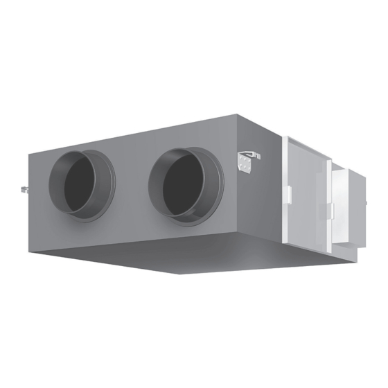
EDUS711116 Dimensions 2. Dimensions VAM300GVJU Unit (in.) 3D073380 VAM470GVJU Unit (in.) 3D073381 VAM-GVJU... - Page 5 Dimensions EDUS711116 VAM600GVJU Unit (in.) 3D073382 VAM1200GVJU Unit (in.) 3D073383 VAM-GVJU...
-
Page 6: Wiring Diagrams
EDUS711116 Wiring Diagrams 3. Wiring Diagrams VAM300GVJU/VAM470GVJU/VAM600GVJU VAM-GVJU... - Page 7 Wiring Diagrams EDUS711116 VAM1200GVJU VAM-GVJU...
-
Page 8: Electric Characteristics
EDUS711116 Electric Characteristics 4. Electric Characteristics 4D073384 VAM-GVJU... -
Page 9: Sound Levels
62.2 58.8 51.4 Notes: 1. These values are based on AHRI Standard 260 “Sound Rating of Ducted Air Moving and Condtioning Equipment.” 2. Power level varies depending on operating and ambient conditions. 3. Ex-H: Extra-high, H: High, L: Low VAM-GVJU... -
Page 10: Octave Band Level
EDUS711116 Sound Levels Octave Band Level 5.3.1 208V 208V, 60Hz VAM300GVJU VAM470GVJU 4D073489 4D073491 VAM600GVJU VAM1200GVJU 4D073495 4D073493 VAM-GVJU... - Page 11 Sound Levels EDUS711116 5.3.2 230V 230V, 60Hz VAM300GVJU VAM470GVJU 4D073490 4D073492 VAM600GVJU VAM1200GVJU 4D073494 4D073496 VAM-GVJU...
-
Page 12: Performance Characteristics
EDUS711116 Performance Characteristics 6. Performance Characteristics VAM300GVJU VAM470GVJU 4D073497 4D073498 VAM600GVJU VAM1200GVJU C: 4D073499 C: 4D073500 VAM-GVJU... -
Page 13: Installation Drawing
Installation Drawing EDUS711116 7. Installation Drawing VAM300GVJU Unit (in.) 3D073389 VAM470GVJU Unit (in.) 3D073390 VAM-GVJU... - Page 14 EDUS711116 Installation Drawing VAM600GVJU Unit (in.) 3D073391 VAM1200GVJU Unit (in.) 3D073392 VAM-GVJU...
-
Page 15: Installation Manual
10-3/8 VAM600GVJU 43-11/16 47-13/16 15-1/4 3-1/2 40-11/16 49-3/4 24-1/2 9-1/4 6-7/16 9-11/16 10-3-8 VAM1200GVJU 43-11/16 47-13/16 – – – 49-5/8 – 19-5/8 – – – – – 100 or higher from the floor for installation in high places 3P034928-7Q VAM-GVJU... - Page 16 EDUS711116 Installation Manual 100 or higher from the floor (φ10) for installation in high places 4 (φ14) VAM1200GVJU 9 11 100 or higher from the floor for installation in high places Floor 3P034928-7Q VAM-GVJU...
-
Page 17: Safety Considerations
Daikin are used, fire or explosion may occur. in minor or moderate injury. • Locate the outdoor air intake vent so that it does not It may also be used to alert against take in exhaust air which contains combustion air, etc. -
Page 18: Before Installation
1 pc. serious solution like a filter box (field supply) during the design process to protect against insect infiltration. Shape Insulation Name Clamp tube Quantity 5 pcs. 1 pc. (Other) • Installation manual • Operation manual Shape English 3P034928-7Q VAM-GVJU... -
Page 19: Selecting Installation Site
• After opening the ceiling hole, make sure ceiling is level if and also ask your customers to read the operation manual. needed. It might be necessary to reinforce the ceiling frame to prevent shaking. Consult an architect or carpenter for details. English 3P034928-7Q VAM-GVJU... -
Page 20: The Method Of Installation
THE METHOD OF INSTALLATION 〈〈As for the parts to be used for installation work, be sure to use the provided accessories and specified parts desig- nated by Daikin.〉〉 • Example of Installation, VAM300GVJU (See figure 2), <VAM470GVJU, VAM600GVJU, VAM1200GVJU> VAM470GVJU, VAM600GVJU (See figure 3), Attach the 4 included duct joints using the included screws. -
Page 21: Duct Connection
(SA). Select materials keeping in mind the fan speed and operat- ing sound of the unit. Consult your Daikin dealer for selec- tion. 10. Set the pitch between the exhaust air outlet (EA) and the outdoor air intake (OA) to at least 3 times the duct diame- ter. -
Page 22: System
• When the air conditioner is not being used, the ERV can be operated in circulation or Duct Direct duct connection system 10-2-2 ventilation modes. • Other specifications are the same as those of the standard system. Remote controller Remote controller English 3P034928-7Q VAM-GVJU... - Page 23 • The centralized controller allows ventilation operation for each Zone con- 10-3-3 zone independently. trol system Remote controller Remote controller Zone 2 [Caution] (1) Adapter PCB : KRP50-2, schedule timer DST301BA61, ON/OFF controller. DCS301C71, Central remote controller: DCS302C71 English 3P034928-7Q VAM-GVJU...
-
Page 24: Electric Wiring Work
7. Do not connect wires of different gauge to the same grounding terminal. Looseness in the connection may deteriorate protection. 8. Keep the power supply wiring distant from other wires to prevent noise. English 3P034928-7Q VAM-GVJU... - Page 25 <OPENING THE CONTROL BOX> 1. Remove the screws fixing the cover and open the control box as shown below. 2. Secure the power supply wiring and the transmission wir- ing with the clamp, as shown in 8-2. English 3P034928-7Q VAM-GVJU...
- Page 26 In case of installing the optional Adapter PCB the installation Insulation tube Clamp (accessory) (accessory) box (option) is needed. See 8-4 on how to install it. Power supply and ground wiring Power supply wiring Ground wire Power supply and Clamp ground wire sheath (accessory) English 3P034928-7Q VAM-GVJU...
- Page 27 • Secure the power supply with the power cord clamp. motor 16. Terminals for no-voltage 6. Connector for damper motor external input • Be sure to give a grounding connection. 7. Power supply 17. Factory setting 8. Terminal block 9. Connector for KPR50-2 English 3P034928-7Q VAM-GVJU...
- Page 28 2. Remove the screws and install the adapter PCB. 3. After wiring, fasten the control box cover. • The adapter circuit board (KRP50-2) can be installed on the inner right-hand side of the control box. The attachment box (optional accessory) is not required. English 3P034928-7Q VAM-GVJU...
-
Page 29: Field Setting And Test Run
9-9 After all setting changes are completed, press Save the settings? Cancel button twice. 9-10 Backlight goes out and “Checking the connection. Please stand by.” is displayed for Setting initialization. After the initialization, the basic screen returns. Press Menu/OK button. Setting confirmation English 3P034928-7Q VAM-GVJU... - Page 30 (1) Mode No. 00: Group controller (2) Mode No. 30: Individual controller * Regarding the setting procedure, refer to the sec- tion “Group number setting for centralized control” in the operating manual of either the ON/OFF con- troller or the central controller. English 3P034928-7Q VAM-GVJU...
-
Page 31: Description Of System And Applicable Patterns
Set the mode No. to “17” for group control or “27” for individual control, the FIRST CODE NO. to “4” and the SECOND CODE NO. to “02” 1. Main remote controller 2. Sub remote controller 3. Maximum transmission wiring length : 1640 ft. English 3P034928-7Q VAM-GVJU... - Page 32 3280 ft. 3. Optional adapter PCB KRP4A72 1. Remote controller 2. Remote controller 3. Transmission wiring can be extended up to 3280 ft. 4. Schedule timer (DST301BA61) 5. Adapter PCB for remote control (KRP4A72) 6. ON/OFF signal English 3P034928-7Q VAM-GVJU...
- Page 33 2. Remote controller 3. Transmission wiring can be extended up to 3280 ft. 4. Schedule timer 5. ON/OFF controller Example: Follow the procedure below to set the centralized group No. 2- 05 to ERV 1. Procedure 1. Remote controller English 3P034928-7Q VAM-GVJU...
- Page 34 Wiring adapter for remote control KRP50-2 (option) (To be placed in the control box of the ERV) 1. Air suction/discharge grille 2. External damper (field supply) 3. 18 in. Inspection hatch 4. Control box 5. Thermal insulation English 3P034928-7Q VAM-GVJU...
- Page 35 6. Clamp (accessory) optional controllers for centralized control. With regard to a closed connector, select one that suits the wire size. Secure the harness with the other wires by using the clamp. English 3P034928-7Q VAM-GVJU...
-
Page 36: Operation Manual
EDUS711116 Operation Manual 9. Operation Manual MODELS VAM300GVJU VAM470GVJU VAM600GVJU 3P034927-7M VAM-GVJU... - Page 37 (14) OA (17) SA (Outdoor air) (Supply air) [Fresh air [Supply air from outside] to inside] (13) EA (Exhaust air) [Exhaust air to outside] (16) RA (Return air) [Return air from inside] (12) Damper motor 3P034927-7M VAM-GVJU...
- Page 38 ERV unit ERV unit Centralized controller Remote controller Remote controller Remote controller • Interlocking system with VRV or SkyAir system Indoor unit ERV unit Remote controller MODELS VAM300GVJU - 600GVJU MODEL VAM1200GVJU MODELS VAM300GVJU - 600GVJU MODEL VAM1200GVJU 3P034927-7M VAM-GVJU...
- Page 39 Operation Manual EDUS711116 3P034927-7M VAM-GVJU...
-
Page 40: Safety Considerations
Improper repair and maintenance may result in electric 2. WHAT TO DO BEFORE OPERATION ......3 shock and fire. Only use accessories made by Daikin that 3. OPERATION PROCEDURE ........... 5 are specifically designed for use with the equipment and 4. - Page 41 (and the indoor duct as well if needed). This may cause the interior of the room to become con- If this is not done completely, water may enter the build- taminated and harming the health. ing, damaging furniture, etc. English 3P034927-7M VAM-GVJU...
-
Page 42: What To Do Before Operation
5. Down button 6. Right button This operation manual is for the following systems with stan- dard control. Before initiating operation, contact your Daikin 7. Left button dealer for the operation that corresponds to your system type 8. On/Off button 9. - Page 43 Setpoint display Used to display the setpoint for the indoor unit. • Use the Celsius/Fahrenheit item in the main menu to • select the temperature unit (Celsius or Fahrenheit). English 3P034927-7M VAM-GVJU...
-
Page 44: Operation Procedure
Displayed if the detailed display item is selected. • Detailed items are not selected by default. • display Displayed when the clock needs to be set. • The schedule function will not work unless the clock is • set. English 3P034927-7M VAM-GVJU... - Page 45 Vent AUTO Return Setting • Selecting and confirming the desired ventilation mode will take you back to the basic screen. (Pressing the Cancel button takes you back to the previous screen without changing the ventilation mode. ) English 3P034927-7M VAM-GVJU...
-
Page 46: Duct Connection
) Indicates that the temperature setpoint and setback temperature setpoint for this time period is not speci- fied. The last active setpoint will be utilized. • Up to five actions can be set for each day. English 3P034927-7M VAM-GVJU... -
Page 47: Maintenance (For A Qualified Service Person Only)
• Do not expose the air filter to fire, as doing so may result in burning. • Do not use gasoline, thinner or other organic solvents. This may cause discoloration or deformation. English 3P034927-7M VAM-GVJU... -
Page 48: Trouble Shooting
IF ONE OF THE FOLLOWING MALFUNCTIONS CAUTION (During Operation) OCCURS, TAKE THE MEASURES SHOWN BELOW AND CONTACT YOUR DAIKIN DEALER • Do not clean touching strongly with a vacuum cleaner. This may crush the mesh of the heat exchanger core. -
Page 49: After-Sales Service
• The error code will flash and installed. the service contact and model Install the air filter and heat exchanger core. name or code may appear. • Notify your Daikin dealer of the AFTER-SALES SERVICE Error code and model name or code. WARNING •... -
Page 50: Accessories
Device Group Control KRP4A72 Adaptor PCB PC Board Adaptor For Humidifier KRP50-2 Installation Box for KRP50-2A90 — (Note: 1) Adaptor PCB 3D073395 Note: 1. Adaptor PCB for humidifier (KRP50-2) can be mounted on the right-hand side of control box. VAM-GVJU... - Page 51 Accessories EDUS711116 VAM-GVJU...
- Page 52 2011 Daikin Industries, LTD. © Daikin, Daikin AC Absolute Comfort and its design, VRV, REFNET, and Quaternity, Daikin Altherma are trademarks of Daikin Industries, Limited. Organization: DAIKIN INDUSTRIES, LTD.
Need help?
Do you have a question about the VAM-GVJU and is the answer not in the manual?
Questions and answers