Table of Contents
Advertisement
Quick Links
Advertisement
Table of Contents

Related Manuals for AXIOMTEK SBC84831 Series


Summary of Contents for AXIOMTEK SBC84831 Series
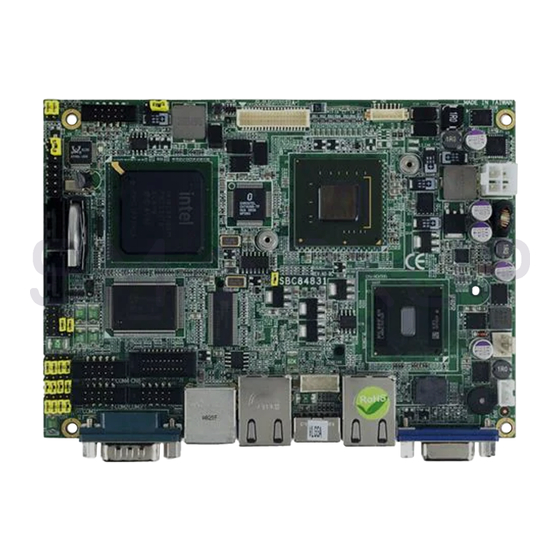
- Page 1 SBC84831 Series ® Intel Atom™ Processor N270 Capa Board with LVDS User’s Manual...
- Page 2 AXIOMTEK does not warrant or assume any legal liability or responsibility for the accuracy, completeness or usefulness of any information in this document. AXIOMTEK does not make any commitment to update the information in this manual.
-
Page 3: Esd Precautions
Wear a wrist-grounding strap, available from most electronic component stores, when handling boards and components. Trademarks Acknowledgments AXIOMTEK is a trademark of AXIOMTEK Co., Ltd. ® Windows is a trademark of Microsoft Corporation. ®... -
Page 4: Table Of Contents
Table of Contents Disclaimers ......................ii ESD Precautions ....................iii CHAPTER 1 INTRODUCTION ..................1 Specifications ..................2 Utilities Supported ................... 3 CHAPTER 2 JUMPERS AND CONNECTORS............5 Board Dimensions and Fixing Holes ............5 Board Layout ................... 7 Jumper Settings ..................9 2.3.1 LCD Voltage Selection Jumper (JP1).......... - Page 5 I/O Port Address Map................30 Interrupt Controller ................31 CHAPTER 4 AMI BIOS SETUP UTILITY..............33 Starting ....................33 Navigation Keys ..................33 Main Menu..................... 34 Advanced Menu ..................35 PCI PnP Menu..................53 Boot Menu ..................... 56 Security Menu ..................60 Chipset Menu ..................
- Page 6 MEMO...
-
Page 7: Chapter 1 Introduction
SBC84831 All-In-One Capa Board User’s Manual CHAPTER 1 INTRODUCTION ® ™ The SBC84831, a Capa board, supports Intel Atom processor ® N270, at FSB 533 MHz. The board integrates chipsets Intel 945GSE and ICH7M that deliver outstanding system performance through high-bandwidth interfaces, multiple I/O functions for interactive applications and various embedded computing solutions. -
Page 8: Specifications
SBC84831 All-In-One Capa Board User’s Manual Specifications ® Intel Atom processor N270 System Chipset ® Intel 945GSE & ICH7M Front-Side Bus 533 MHz BIOS American Megatrends Inc. BIOS. 8Mbit SPI Flash, DMI, Plug and Play “Load Optimized Default” to backup customized Setting in the BIOS flash chip to prevent from CMOS battery fail System Memory One 200-pin unbuffered DDR2 SO-DIMM sockets... -
Page 9: Utilities Supported
SBC84831 All-In-One Capa Board User’s Manual Watchdog Timer 1~255 seconds; up to 255 levels Ethernet Dual port with RTL8111B for Gigabit/Fast Ethernet Audio AC’97 Audio compliant (with Speaker/line-out & MIC-in) via ALC203 Internal Audio features for speaker-out & MIC-in & Line-in via Box Header connector Power Management ACPI (Advanced Configuration and Power Interface) - Page 10 SBC84831 All-In-One Capa Board User’s Manual MEMO Introduction...
-
Page 11: Chapter 2 Jumpers And Connectors
SBC84831 All-In-One Capa Board User’s Manual CHAPTER 2 JUMPERS AND CONNECTORS Board Dimensions and Fixing Holes 101.47 101.47 95.26 95.26 81.29 ATX1 69.60 66.55 SATA1 57.90 SATA2 42.32 33.02 CN5 JP4 COM4 23.72 USB1 CN10 JP10 JP11 0.00 0.00 3.18 3.18 COM2 COM3... - Page 12 SBC84831 All-In-One Capa Board User’s Manual 146.05 70.05 46.53 SCN1 26.54 SCF1 104.65 73.28 32.66 14.73 47.50 1.90 Solder Side Jumpers and Connectors...
-
Page 13: Board Layout
SBC84831 All-In-One Capa Board User’s Manual Board Layout Component Side Jumpers and Connectors... - Page 14 SBC84831 All-In-One Capa Board User’s Manual Solder Side Jumpers and Connectors...
-
Page 15: Jumper Settings
SBC84831 All-In-One Capa Board User’s Manual Jumper Settings Proper jumer settings configure the SBC84831 to meet your application purpose. We are herewith listing a summary table of all jumpers and default settings for onboard devices, respectively. Jumper Default Setting Jumper Setting LVDS Voltage Selection Short 1-2 Default: 3.3V... -
Page 16: Lcd Voltage Selection Jumper (Jp1)
SBC84831 All-In-One Capa Board User’s Manual 2.3.1 LCD Voltage Selection Jumper (JP1) The board supports +3.3V or +5V flat panel displays. Configure the jumper JP1 to the appropriate voltage of the flat panel. Description Function Jumper Setting LCD Voltage 3.3V Selection (Default) 2.3.2 Audio Output Jumper (JP2) -
Page 17: Auto Power On Jumper (Jp3)
SBC84831 All-In-One Capa Board User’s Manual 2.3.3 Auto Power On Jumper (JP3) When Jumper JP3 is set OPEN for AC power input, the system will be automatically power ON without pressing soft power button; when JP3 is SHORT for AC power input, it is necessary to manually press soft power button to make the system power ON. -
Page 18: Cmos Clear Jumper (Jp5)
SBC84831 All-In-One Capa Board User’s Manual 2.3.5 CMOS Clear Jumper (JP5) You may need to use this jumper is to clear the CMOS memory if incorrect settings in the Setup Utility. Description Function Jumper Setting CMOS Clear Normal (Default) Clear CMOS 2.3.6 COM5 Mode Selection Jumper (JP6) The jumper selects the CN6 COM5 ports’... -
Page 19: Com6 Mode Selection Jumper (Jp7)
SBC84831 All-In-One Capa Board User’s Manual 2.3.7 COM6 Mode Selection Jumper (JP7) The jumper selects the CN6 COM6 ports’ DCD and RI mode. Description Function Jumper Setting COM6 CN6 Pin 11=5V Pin 11=DCD (Default) CN6 Pin 18=12V CN6 Pin 18=RI (Default) Jumpers and Connectors... -
Page 20: Com3 Mode Selection Jumper (Jp8)
SBC84831 All-In-One Capa Board User’s Manual 2.3.8 COM3 Mode Selection Jumper (JP8) The jumper selects the COM3 ports’ DCD and RI mode. Description Function Jumper Setting COM3 Pin 1=5V Pin 1=DCD (Default) Pin 8=12V Pin 8=RI (Default) Jumpers and Connectors... -
Page 21: Com4 Mode Selection Jumper (Jp9)
SBC84831 All-In-One Capa Board User’s Manual 2.3.9 COM4 Mode Selection Jumper (JP9) The jumper selects the COM4 ports’ DCD and RI mode. Description Function Jumper Setting COM4 Pin 1=5V Pin 1=DCD (Default) Pin 8=12V Pin 8=RI (Default) Jumpers and Connectors... -
Page 22: Com1 Mode Selection Jumper (Jp10)
SBC84831 All-In-One Capa Board User’s Manual 2.3.10 COM1 Mode Selection Jumper (JP10) The jumper selects the COM1 ports’ DCD and RI mode. Description Function Jumper Setting COM1 Pin 1=5V Pin 1=DCD (Default) Pin 9=12V Pin 9=RI (Default) Jumpers and Connectors... -
Page 23: Com2 Mode Selection Jumper (Jp11)
SBC84831 All-In-One Capa Board User’s Manual 2.3.11 COM2 Mode Selection Jumper (JP11) The jumper selects the COM2 ports’ DCD and RI mode. Description Function Jumper Setting COM2 Pin 1=5V Pin 1=DCD (Default) Pin 8=12V Pin 8=RI (Default) Jumpers and Connectors... -
Page 24: Connectors
Connectors connect the board with other parts of the system. Loose or improper connection might cause problems. Make sure all connectors are properly and firmly connected. Here is a summary table shows you all connectors on the SBC84831 Series. Connector Label... -
Page 25: Atx 4 Pin 12V Connector (Atx1)
SBC84831 All-In-One Capa Board User’s Manual 2.4.1 ATX 4 Pin 12V Connector (ATX1) Connect it to the power supply ATX12V power. Signal +12V +12V 2.4.2 LVDS Backlight Connector (CN1) The CN1 is DF13-7S-1.25C 7-pin connectors for inverter that we strongly recommend you to use the matching DF13-7S-1.25C connector. -
Page 26: Lvds Flat Panel Connector (Cn3)
SBC84831 All-In-One Capa Board User’s Manual 2.4.4 LVDS Flat Panel Connector (CN3) The board has a 40-pin connector CN3 for LVDS Interface LCD. It is strongly recommended to use the matching GLA1001WV-S-2x20P 40- pin connector for LVDS on the board. Signal Signal VCCM... -
Page 27: Flat Panel Bezel Connector (Cn4)
SBC84831 All-In-One Capa Board User’s Manual 2.4.5 Flat Panel Bezel Connector (CN4) Power LED This 3-pin connector has Pin 1 and Pin 5 that connect the system power LED indicator to its corresponding switch on the case. Pin 1 is assigned as +, and Pin 3, Pin 5 as -. The Power LED lights up when the system is powered ON. -
Page 28: Digital I/O Port Connector (Cn5)
SBC84831 All-In-One Capa Board User’s Manual panel’s ATX power button to the CPU card, which allows users to control ATX power supply to be power on/off. System Reset Switch Pin 11 and 12 can be connected to the case-mounted reset switch that reboots your computer, not turns OFF the power switch. -
Page 29: Serial Port5 & Serial Port6 (Cn6)
SBC84831 All-In-One Capa Board User’s Manual 2.4.7 Serial Port5 & Serial Port6 (CN6) Signal Signal DCD5 DSR5 RXD5 RTS5 TXD5 CTS5 DTR5 N.C. DCD6 DSR6 RXD6 RTS6 TXD6 CTS6 DTR6 N.C. 2.4.8 SMBus Connector (CN7) Connector CN7 is for SMBUS interface support. Signal CLOCK DATA... -
Page 30: Keyboard And Ps/2 Mouse Connector (Cn8)
SBC84831 All-In-One Capa Board User’s Manual 2.4.9 Keyboard and PS/2 Mouse Connector (CN8) The board supports a keyboard and Mouse interface. Connector is a DIN connector for PS/2 keyboard Connection VIA “Y” Cable. Signal Keyboard Data Mouse Data Keyboard Clock Mouse Clock 2.4.10 VGA Connector (CN9) The board has three connectors to support CRT VGA and flat panel... -
Page 31: Serial Port1 Connector (Com1)
SBC84831 All-In-One Capa Board User’s Manual 2.4.11 Serial Port1 Connector (COM1) The COM 1 Port connector is a standard DB-9 connector. Signal DCD, Data carrier detect RXD, Receive data TXD, Transmit data DTR, Data terminal ready GND, ground DSR, Data set ready RTS, Request to send CTS, Clear to send RI, Ring indicator... -
Page 32: Power Output Connector (Cn10)
SBC84831 All-In-One Capa Board User’s Manual 2.4.13 Power output Connector (CN10) Signal +12V 2.4.14 Ethernet Connectors (LAN1, LAN2) The RJ-45 connector is for Ethernet. To connect the board to a 1000/100/10 Base-T hub, just plug one end of the cable into connector and connect the other end (phone jack) to a 1000/100/10-Base-T hub. -
Page 33: Usb Port Connector (Usb2)
SBC84831 All-In-One Capa Board User’s Manual 2.4.16 USB Port Connector (USB2) Signal Signal USB VCC0 USB VCC0 (5VSBY) (5VSBY) USB D0- USB D1- USB D0+ USB D1+ Ground (GND) Ground (GND) 2.4.17 Internal USB Connector (USB1) These Universal Serial Bus (USB) connectors on this board are for installing versatile USB interface peripherals. -
Page 34: Compactflash™ Socket (Scf1)
SBC84831 All-In-One Capa Board User’s Manual ™ 2.4.18 CompactFlash Socket (SCF1) The board is equipped with a CompactFlash disk type-II socket on the solder side to support an IDE interface CompactFlash disk card with DMA mode supported. The socket is especially designed to avoid incorrect installation of the CompactFlash disk card. -
Page 35: Chapter 3 Hardware Description
Make sure all correct settings are arranged for your installed microprocessor to prevent the CPU from damages. BIOS The SBC84831 Series uses AMI Plug and Play BIOS with a single 8Mbit SPI Flash, DMI, Plug and Play. System Memory... -
Page 36: I/O Port Address Map
SBC84831 All-In-One Capa Board User’s Manual I/O Port Address Map There are total 1KB port addresses (under OS WinXP) available for assignment to other devices via I/O expansion cards. Hardware Description... -
Page 37: Interrupt Controller
SBC84831 All-In-One Capa Board User’s Manual Interrupt Controller The SBC84831 Series is a 100% PC compatible control board. It consists of 16 interrupt request lines, and four out of them can be programmable. The mapping list of the 16 interrupt request lines is shown as the following table. - Page 38 SBC84831 All-In-One Capa Board User’s Manual MEMO Hardware Description...
-
Page 39: Chapter 4 Ami Bios Setup Utility
SBC84831 All-In-One Capa Board User’s Manual CHAPTER 4 AMI BIOS SETUP UTILITY This chapter provides users with detailed description how to set up basic system configuration through the AMIBIOS8 BIOS setup utility. Starting To enter the setup screens, follow the steps below: Turn on the computer and press the <Del>... -
Page 40: Main Menu
SBC84831 All-In-One Capa Board User’s Manual The <F10> key allows you to save any changes you have made and exit Setup. Press the <F10> key to save your changes. The <Esc> key allows you to discard any changes you have made and exit the Setup. Press the <Esc>... -
Page 41: Advanced Menu
SBC84831 All-In-One Capa Board User’s Manual values through the keyboard. Press the <Tab> key or the <Arrow> keys to move between fields. The date must be entered in MM/DD/YY format. The time is entered in HH:MM:SS format. Advanced Menu The Advanced menu allows users to set configuration of the CPU and other system devices. - Page 42 SBC84831 All-In-One Capa Board User’s Manual Configure advanced CPU settings This screen shows the CPU Configuration, and you can change the value of the selected option. Max CPUID Value Limit You can enable this item to let legacy operating systems boot even without support for CPUs with extended CPU ID functions.
- Page 43 SBC84831 All-In-One Capa Board User’s Manual technology. Enhanced C-States This item allows you to enable or disable any available enhanced C-states ( C1E, C2E, C3E, C4E and Hard C4E). IDE Configuration You can use this screen to select options for the IDE Configuration, and change the value of the selected option.
- Page 44 SBC84831 All-In-One Capa Board User’s Manual Primary/Secondary/Third IDE Master/Slave Select one of the hard disk drives to configure IDE devices installed in the system by pressing <Enter> for more options. SuperIO Configuration You can use this screen to select options for the SuperIO Configuration, and change the value of the selected option.
- Page 45 SBC84831 All-In-One Capa Board User’s Manual Interrupt Request address of serial port 2. The Optimal setting is 2F8/IRQ3. The Fail-Safe setting is Disabled. Serial Port2 IRQ This item specifies the IRQ used by the serial port 2. Serial Port2 Mode This item specifies the mode used by the serial port 2.
- Page 46 SBC84831 All-In-One Capa Board User’s Manual Hardware Health Configuration This screen shows the Hardware Health Configuration, and a description of the selected item appears on the right side of the screen. System Temperature/CPU Temperature These items display the temperature of CPU and System, Vcore, etc.
- Page 47 SBC84831 All-In-One Capa Board User’s Manual ACPI Settings You can use this screen to select options for the ACPI Settings, and change the value of the selected option. A description of the selected item appears on the right side of the screen. AMI BIOS Setup Utility...
- Page 48 SBC84831 All-In-One Capa Board User’s Manual General ACPI Configuration Scroll to this item and press <Enter> to view the General ACPI Configuration sub menu, which contains General ACPI (Advanced Configuration and Power Management Interface) options for your configuration. AMI BIOS Setup Utility...
- Page 49 SBC84831 All-In-One Capa Board User’s Manual Advanced ACPI Configuration Scroll to this item and press <Enter> to view the Advanced ACPI Configuration sub menu, which contains Advanced ACPI (Advanced Configuration and Power Management Interface) options for your configuration. AMI BIOS Setup Utility...
- Page 50 SBC84831 All-In-One Capa Board User’s Manual Chipset ACPI Configuration Scroll to this item and press <Enter> to view the Chipset ACPI Configuration sub menu, which contains Chipset ACPI (Advanced Configuration and Power Management Interface) options for your configuration. AMI BIOS Setup Utility...
- Page 51 SBC84831 All-In-One Capa Board User’s Manual APM Configuration You can use this screen to select options for the APM Configuration, and change the value of the selected option. A description of the selected item appears on the right side of the screen.
- Page 52 SBC84831 All-In-One Capa Board User’s Manual inactivity has expired. The default setting is Suspend. This setting prevents the BIOS from initiating Disabled any power saving modes concerned with the video display or monitor. This option places the monitor into suspend mode after the specified period of display inactivity has expired.
- Page 53 SBC84831 All-In-One Capa Board User’s Manual power button on the front of the computer chassis is used. The default setting is On/Off. Pushing the power button turns the computer On/Off on or off. This is the default setting. This is the default setting.
- Page 54 SBC84831 All-In-One Capa Board User’s Manual MPS Configuration This screen shows the MPS (Multi Processor Specification) Configuration, and you can change its value. A description of the selected item appears on the right side of the screen. MPS Revision Use this item to select MPS (Multi Processor Specification) Revision 1.1 or 1.4.
- Page 55 SBC84831 All-In-One Capa Board User’s Manual PCI Express Configuration This screen shows the PCI Express Configuration, and you can change its value. A description of the selected item appears on the right side of the screen. Active State Power-Management Use this item to enable or disable the function of Active State Power-Management to provide you with lower power consumption.
- Page 56 SBC84831 All-In-One Capa Board User’s Manual SB PCIE Ports Configuration Scroll to this item and press <Enter> to view the SB PCIE Ports Configuration sub menu, which contains several options for your configuration. AMI BIOS Setup Utility...
- Page 57 SBC84831 All-In-One Capa Board User’s Manual USB Configuration You can use this screen to select options for the USB Configuration, and change the value of the selected option. A description of the selected item appears on the right side of the screen.
- Page 58 SBC84831 All-In-One Capa Board User’s Manual USB Mass Storage Device Configuration Scroll to this item and press <Enter> to view the USB Mass Storage Device Configuration sub menu, which contains several options for your configuration. AMI BIOS Setup Utility...
-
Page 59: Pci Pnp Menu
SBC84831 All-In-One Capa Board User’s Manual PCI PnP Menu The PCI PnP menu allows users to change the advanced settings for PCI/PnP devices. AMI BIOS Setup Utility... - Page 60 SBC84831 All-In-One Capa Board User’s Manual Clear NVRAM Use this item to clear the data in the NVRAM (CMOS). Here are the options for your selection, No and Yes. Plug & Play O/S When the setting is No, Use this item to configure all the devices in the system.
- Page 61 SBC84831 All-In-One Capa Board User’s Manual selection, No and Yes. Palette Snooping Some old graphic controllers need to “snoop” on the VGA palette, and then map it to their display as a way to provide boot information and VGA compatibility. This item allows such snooping to take place.
-
Page 62: Boot Menu
SBC84831 All-In-One Capa Board User’s Manual Boot Menu The Boot menu allows users to change boot options of the system. You can select any of the items in the left frame of the screen to go to the sub menus: Boot Settings Configuration Boot Device Priority Removable Drives... - Page 63 SBC84831 All-In-One Capa Board User’s Manual Boot Settings Configuration Quick Boot Enabling this item lets the BIOS skip some power on self tests (POST). The default setting is Enabled. LAN1/LAN2 Boot Use these items to enable or disable the Boot ROM function of the onboard LAN chip when the system boots up.
- Page 64 SBC84831 All-In-One Capa Board User’s Manual NumLock. The default setting is On. PS/2 Mouse Support This item determines if the BIOS should reserve IRQ12 for the PS/2 mouse or allow other devices to make use of this IRQ. Here are the options for your selection, Auto, Enabled and Disabled.
- Page 65 SBC84831 All-In-One Capa Board User’s Manual Removable Drives Use this screen to view the removable drives in the system. The BIOS will attempt to arrange the removable drive boot sequence automatically. You can also change the booting sequence. AMI BIOS Setup Utility...
-
Page 66: Security Menu
SBC84831 All-In-One Capa Board User’s Manual Security Menu The Security menu allows users to change the security settings for the system. Supervisor Password This item indicates whether a supervisor password has been set. If the password has been installed, Installed displays. If not, Not Installed displays. User Password This item indicates whether a user password has been set. - Page 67 SBC84831 All-In-One Capa Board User’s Manual password. Clear User Password Select this option and press <Enter> to access the sub menu. You can use the sub menu to clear the user password. Boot Sector Virus Protection This option is near the bottom of the Security Setup screen.
-
Page 68: Chipset Menu
SBC84831 All-In-One Capa Board User’s Manual Chipset Menu The Chipset menu allows users to change the advanced chipset settings. You can select any of the items in the left frame of the screen to go to the sub menus: North Bridge Configuration South Bridge Configuration For items marked with “... - Page 69 SBC84831 All-In-One Capa Board User’s Manual North Bridge Configuration DRAM Frequency This item allows you to control the Memory Clock. Configure DRAM Timing by SPD This item can enable or disable DRAM timing by SPD (Serial Presence Detect) device, which is a small EEPROM chip on the memory module, containing important information about the module speed, size, addressing mode and various parameters.
- Page 70 SBC84831 All-In-One Capa Board User’s Manual as the primary boot device. Internal Graphics Mode Select This item allows you to select the amount of system memory used by the internal graphics device. Video Function Configuration Press <Enter> for the sub-menu for setting up video function.
- Page 71 SBC84831 All-In-One Capa Board User’s Manual South Bridge Configuration AMI BIOS Setup Utility...
- Page 72 SBC84831 All-In-One Capa Board User’s Manual USB Function This item allows you to enable or disable USB function. USB 2.0 Controller This item allows you to enable or disable the USB 2.0 controller. Audio Controller This item allows you to enable or disable the audio support.
-
Page 73: Exit Menu
SBC84831 All-In-One Capa Board User’s Manual PCIE Port Configuration This item allows you to set or disable the PCI Express Ports. Exit Menu The Exit menu allows users to load your system configuration with optimal or failsafe default values. Save Changes and Exit When you have completed the system configuration changes, select this option to leave Setup and reboot the computer so the new system configuration... - Page 74 SBC84831 All-In-One Capa Board User’s Manual exit. Discard Changes Use this item to abandon all changes. Load Optimal Defaults It automatically sets all Setup options to a complete set of default settings when you select this option. The Optimal settings are designed for maximum system performance, but may not work best for all computer applications.
-
Page 75: Appendix A Watchdog Timer
SBC84831 All-In-One Capa Board User’s Manual APPENDIX A WATCHDOG TIMER Watchdog Timer Setting After the system stops working for a while, it can be auto-reset by the Watchdog Timer. The integrated Watchdog Timer can be set up in the system reset mode by program. Using the Watchdog Function Start ↓... - Page 76 SBC84831 All-In-One Capa Board User’s Manual Timeout Value Range 1 to 255 Minute / Second Program Sample O 2E 87 O 2E 87 O 2E 07 O 2F 08 Logical Device 8 O 2E 30 Activate O 2F 01 O 2E F5 Set Minute or Second O 2F N N=08 (Min),00(Sec)
-
Page 77: Appendix Bdigital I/O
SBC84831 All-In-One Capa Board User’s Manual APPENDIX B DIGITAL I/O Signal Signal Digital Input 0 Digital Output 0 (48D / Bit4) (Value M / Bit0) Digital Input 1 Digital Output 1 (48D / Bit5) (Value M / Bit1) Digital Input 2 Digital Output 2 (48D / Bit6) (Value M / Bit2) - Page 78 SBC84831 All-In-One Capa Board User’s Manual Digital I/O Software Programming GPI program sample: Read Bit4~Bit6 Status (GPI0~2) I 48D GPO program sample: O 2E 87 O 2E 87 O 2E 07 O 2F 08 Select Device 8 O 2E 30 O 2F 04 Set GPIO6 O 2E E4...
Need help?
Do you have a question about the SBC84831 Series and is the answer not in the manual?
Questions and answers