
Related Manuals for AXIOMTEK ICO120-E3350-A


Summary of Contents for AXIOMTEK ICO120-E3350-A
- Page 1 ICO120-E3350-A ICO120-E3350-B ICO120-E3350-C ICO120-E3350-E Robust Din-rail Fanless Embedded System User’s Manual...
- Page 2 Axiomtek does not make any commitment to update the information in this manual. Axiomtek reserves the right to change or revise this document and/or product at any time without notice. No part of this document may be reproduced, stored in a retrieval system, or transmitted, in any form or by any means, electronic, mechanical, photocopying, recording, or otherwise, without the prior written permission of Axiomtek Co., Ltd.
- Page 3 Safety Precautions Before getting started, please read the following important safety precautions. The ICO120-E3350-A/B/C does not come equipped with an operating system. An operating system must be loaded first before installing any software into the computer. Be sure to ground yourself to prevent static charge when installing the internal components.
- Page 4 When use with desk top Class I power adapter, the Power Cord only shall only connect to a socket-outlet with earthing connection.
-
Page 5: Classification
Classification Degree of production against electric shock: not classified Degree of protection against the ingress of water: IP30 Equipment not suitable for use in the presence of a flammable anesthetic mixture with air or with oxygen or nitrous oxide. Mode of operation: Continuous Type of protection against electric shock: Class I equipment General Cleaning Tips You may need to read the following precautions carefully before you begin to clean the... -
Page 6: Cleaning Tools
Cleaning Tools Although many companies have created products to help improve the process of cleaning your computer and peripherals users can also use household items to clean their computers and peripherals. Below is a listing of items you may need or want to use while cleaning your computer or computer peripherals. -
Page 7: Scrap Computer Recycling
Axiomtek distributor as soon as possible for the suitable solution. For the computers that are no longer useful or no longer working well, please contact your Axiomtek distributor for recycling and we will make the proper arrangement. -
Page 8: Table Of Contents
Table of Contents Disclaimers ......................ii Safety Precautions ....................iii Classification ......................v General Cleaning Tips .................... v Cleaning Tools ......................vi Scrap Computer Recycling ................... vii CHAPTER 1 INTRODUCTION ................1 General Description ................1 System Specifications ................2 Dimensions ..................... - Page 10 This page is intentionally left blank. viii...
-
Page 12: Chapter 1 Introduction
ICO120-E3350-A/B/C/E features an extra-low power consumption Intel® Celeron® N3350(1.5GHz/4- cores) processor supporting an industrial temperature range of-40℃ to +70℃. Its front accessible I/O cabling is very convenient for wiring and maintenance. ICO120-E3350-A/B/C/E offers an HDMI output, making it particularly well-suited for communication control, SCADA and industrial automation. Its compact size with Din-rail mounting allows for easy installation into the control cabinet. -
Page 13: System Specifications
◼ Passed CE, FCC, UL, UKCA certification ⚫ O.S. Supported ® ICO120-E3350-A/B/C/E supports Windows 10, Windows® 11 and Linux package. For storage device, ICO120-E3350-A/B/C/E supports one mSATA. System Specifications 1.2.1 ⚫ Onboard Intel ® Celeron® N3350 (2-core, 1.1 GHz) processor. - Page 14 ⚫ Power Input DC Terminal block: Wide-range 12 - 24V. OVP and Reverse protection. Signal 1.2.9 COM: ICO120-E3350-A & ICO120-E3350-C ⚫ Front side DB9 supports RS-232/422/485 which can be selected by BIOS. ⚫ Supports Auto Flow Control in RS485 mode.
- Page 15 ICO120-E Series User’s Manual 1.2.10 DIO: ICO120-E3350-B & ICO120-E3350-E ⚫ Bottom side DB9 female connector supports 8 bits TTL level programmable digital input/output ⚫ The voltage of TTL is 5V ⚫ The programming is as follow: - I/O sink current is 8~10mA - Input/Output can be programmed Signal DIO0...
- Page 16 ⚫ 1.2.20 System I/O Outlets ⚫ Two 9-pin D-Sub connectors: ICO120-E3350-A: COM1 (male connector), COM2 (male connector) ICO120-E3350-B: COM1 (male connector), DIO (female connector) ICO120-E3350-C: COM1 (male connector), CANbus1 (male connector) ICO120-E3350-C: CANbus1 (male connector) , DIO (female connector) ⚫...
-
Page 17: Dimensions
ICO120-E Series User’s Manual Dimensions The following diagrams show you the dimensions and outlines of the ICO120-E3350-A/B/C/E. Introduction... -
Page 18: I/O Outlets
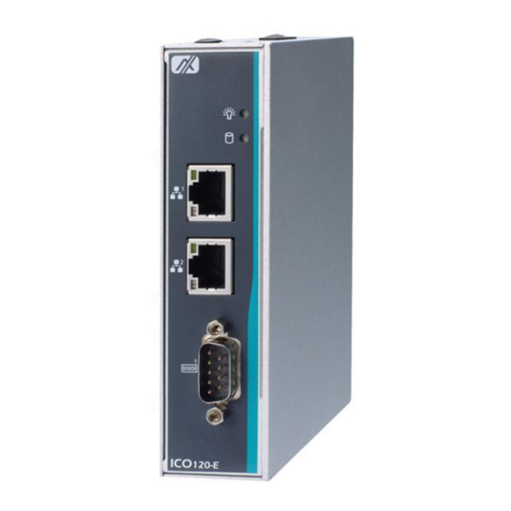
ICO120-E Series User’s Manual I/O Outlets The following figures show you I/O outlets from the front view and top view of the ICO120- E3350-A/B/C/E. Introduction... - Page 19 ICO120-E Series User’s Manual The following figures show you I/O outlets from the bottom view of the ICO120- E3350-A/B/C/E. Introduction...
-
Page 21: Chapter 2 Hardware Installation
ICO120-E Series User’s Manual CHAPTER 2 HARDWARE INSTALLATION The ICO120-E3350-A/B/C/E is convenient for your various hardware configurations, such as Memory Module and mSATA.Chapter 2 will show you how to install the hardware. It includes: Installing the Memory Module Step 1 Turn off the system. - Page 22 ICO120-E Series User’s Manual Step 4 Use two fingers to hold the memory module and insert the gold figure into the slot and push the module down. Step 5 The memory module is locked by two latches on the sides. We strongly recommend using “LDC737”...
-
Page 23: Installing The Msata
ICO120-E Series User’s Manual Installing the mSATA Step 1 Turn off the system. Step 2 Loosen all the screws of the cover and remove the cover from the system. Insert the mSATA into the slot which marking with “mSATA / USB / PCIe”. Step 3 Hardware Installation... - Page 24 ICO120-E Series User’s Manual Step 4 Tighten the screw tightly. Step 5 Put the cover back to the system and tighten the screws then close the chassis. Hardware Installation...
-
Page 25: Installing Din-Rail Mounting
ICO120-E Series User’s Manual Installing Din-rail Mounting The ICO120-E3350-A/B/C/E provides Din-rail Mount as below: Step 1 Prepare Din-rail Mount assembling components (screws and bracket). Step 2 Assemble the bracket to the system and tighten the screws. Hardware Installation... -
Page 26: Installing Wall Mounting (Optional)
ICO120-E Series User’s Manual Installing Wall Mounting (optional) The ICO120-E3350-A/B/C/E provides Wall Mounting that customers can install as below: Step 1 Prepare Wall Mount assembling components (screws and bracket). Step 2 Assemble the bracket to the system and tighten the screws. -
Page 27: Chapter 3 Ami Uefi Bios Utility
ICO120-E Series User’s Manual CHAPTER 3 AMI UEFI BIOS UTILITY The AMI UEFI BIOS provides users with a built-in Setup program to modify basic system configuration. All configured parameters are stored in a flash-backed-up to save the Setup information whenever the power is turned off Entering Setup To enter the setup screens, follow the steps below: Turn on the computer and press the <Del>... -
Page 28: The Main Menu
ICO120-E Series User’s Manual The Main Menu Once you enter the AMI BIOS Aptio Setup Utility, the Main Menu appears on the screen. In the Main Menu, there are several Setup functions and a couple of Exit options for your selection. Use Select Screen Keys (or Move Keys) to select the Setup Page you intend to configure then press <Enter>... -
Page 29: Advanced Features
ICO120-E Series User’s Manual Advanced Features This Advanced section allows users to configure and improve your system, or to set up some system features according to your preference. You can select any of the items in the left frame of the screen to go to the sub menus: AMI UEFI BIOS Utility... - Page 30 ICO120-E Series User’s Manual CPU Configuration Scroll to this item and press <Enter> to view the CPU Configuration information. (Please refer to the graphics below.) AMI UEFI BIOS Utility...
- Page 31 ICO120-E Series User’s Manual SATA Configuration Scroll to this item and press <Enter> to view the SATA Configuration information. (Please refer to the graphics below.) AMI UEFI BIOS Utility...
- Page 32 ICO120-E Series User’s Manual AMI UEFI BIOS Utility...
- Page 33 ICO120-E Series User’s Manual PCIe/mSATA Mini Card Configuration You can choose the PCIe or mSATA modein thein BIOS menu. AMI UEFI BIOS Utility...
- Page 34 ICO120-E Series User’s Manual AMI UEFI BIOS Utility...
- Page 35 ICO120-E Series User’s Manual USB Configuration Scroll to this item and press <Enter> to view the USB Configuration information. (Please refer to the graphics below.) AMI UEFI BIOS Utility...
- Page 36 ICO120-E Series User’s Manual H/W Monitor Scroll to this item and press <Enter> to view the monitor hardware status. (Please refer to the graphics below.) AMI UEFI BIOS Utility...
- Page 37 ICO120-E Series User’s Manual F81804 Super IO Configuration The default setting for the Serial Port is RS232. You can change the setting by selecting the value you want in each COM Port Type. The COM supports RS422 & RS485 mode and high-speed mode. You can enable High-speed mode==in the BIOS menu.
- Page 38 ICO120-E Series User’s Manual AMI UEFI BIOS Utility...
- Page 39 ICO120-E Series User’s Manual Serial Port Console Redirection The default setting for the console redirection function is [Disabled] (Please refer to the graphics below.) AMI UEFI BIOS Utility...
- Page 40 ICO120-E Series User’s Manual And you can further change the setting by selecting or setting the value you want in each function as the following pictures. AMI UEFI BIOS Utility...
- Page 41 Utility Configuration BIOS flash utility is a tool for flash BIOS on setup menu, follow the step to flash BIOS. Create a folder and rename it to Axiomtek on the root of USB storage (Ex: X:\Axiomtek) Copy the BIOS file to the Axiomtek folder (Ex: X:\Axiomtek\SBC8783D.100) (Note: BIOS file name must contain the...
- Page 42 ICO120-E Series User’s Manual AMI UEFI BIOS Utility...
- Page 43 ICO120-E Series User’s Manual AMI UEFI BIOS Utility...
-
Page 44: Chipset Feature
ICO120-E Series User’s Manual Chipset Feature AMI UEFI BIOS Utility... - Page 45 ICO120-E Series User’s Manual AMI UEFI BIOS Utility...
-
Page 46: Security
ICO120-E Series User’s Manual Security The default setting for Administrator Password is “Not setting passwords”. The Security menu allows users to change the security settings for the system. You can set the password for both Administrator Password and the User Password. (Please refer to the graphics below.) Note: The BIOS default has no password, when user created the password, please remember the password number, if users forget password the RMA is the only solution. -
Page 47: Boot Mode
ICO120-E Series User’s Manual Boot Mode Boot has UEFI,Legacy,Compatible mode for selection. The default setting boot mode is [UEFI Mode] The default setting Launch UEFI PXE OpROM policy is [Disable] (Please refer to the graphics below.) AMI UEFI BIOS Utility... - Page 48 ICO120-E Series User’s Manual When select Compatible Mode Compatible Mode: When use PCIe to SATA device, option ROM can use this Mode setting. The default setting PXE OpROM is [Disable] The default setting Video OpROM is [UEFI] The default setting Video OpROM is [UEFI] AMI UEFI BIOS Utility...
- Page 49 ICO120-E Series User’s Manual The Boot Option Priorities can select by Boot Option #1, #2…, If the user is using a USB Device. (Please refer to the graphics below.) AMI UEFI BIOS Utility...
-
Page 50: Save & Exit
ICO120-E Series User’s Manual Save & Exit This section allows you to determine whether or not to accept your modifications. Type “Y” to quit the setup utility and save all changes. Type “N” to bring you back to the Previous Setup utility. - Page 51 ICO120-E Series User’s Manual This page is intentionally left blank. AMI UEFI BIOS Utility...
-
Page 52: Appendix Awatchdog Timer
ICO120-E Series User’s Manual APPENDIX A WATCHDOG TIMER About Watchdog Timer After the system stops working for a while, it can be auto-reset by the watchdog timer. The integrated watchdog timer can be set up in the system reset mode by program. How to Use Watchdog Timer The following example enables configuration using debug tool.
Need help?
Do you have a question about the ICO120-E3350-A and is the answer not in the manual?
Questions and answers