
Related Manuals for AXIOMTEK SHB110 Series


Summary of Contents for AXIOMTEK SHB110 Series
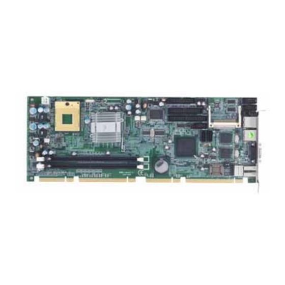
- Page 1 SHB110 Series ® ™ ™ Intel Core 2 Duo/ Core ™ Core Solo/ PICMG 1.3 Full-Size Single Board Computer User’s Manual...
- Page 2 AXIOMTEK does not warrant or assume any legal liability or responsibility for the accuracy, completeness or usefulness of any information in this document. AXIOMTEK does not make any commitment to update the information in this manual.
-
Page 3: Esd Precautions
Wear a wrist-grounding strap, available from most electronic component stores, when handling boards and components. Trademarks Acknowledgments AXIOMTEK is a trademark of AXIOMTEK Co., Ltd. ® Windows is a trademark of Microsoft Corporation. Phoenix & AWARD are trademarks of Phoenix Technology Ltd. -
Page 4: Table Of Contents
Table of Contents Disclaimers ......................ii ESD Precautions ....................iii C h a p t e r 1 ......................1 Introduction......................... 1 Specifications ................. 2 Utilities Supported ................. 3 Block Diagram ................4 I/O Bracket ..................4 C h a p t e r 2 ......................5 Jumpers and Connectors .................. - Page 5 C h a p t e r 4 ......................27 Hardware Description ....................27 Microprocessors ................27 BIOS....................27 System Memory................27 I/O Port Address Map ..............28 C h a p t e r 5 ......................29 Award BIOS Utility ....................29 Entering Setup................
- Page 6 MEMO...
-
Page 7: Introduction
SHB110 Socket M Full-Size SBC User’s Manual C h a p t e r 1 Introduction The SHB110 PICMG 1.3 full-size Single Board Computer supports ™ ™ ™ ® Intel Core 2 Duo/ Core Duo/Core Solo processors with FSB ® 533/667 MHz. -
Page 8: Specifications
SHB110 Socket M Full-Size SBC User’s Manual Specifications ® ™ ™ ™ Intel Core 2 Duo Core Duo/Core CPU: Solo processors ® 945GME and ICH7M-DH System Chipset: Intel CPU Socket: Socket M Front-Side Bus: 533/667 MHz BIOS Award PnP Flash BIOS System Memory Two x 240-pin DDR2 DIMM sockets Maximum up to 4GB DDR2 memory... -
Page 9: Utilities Supported
SHB110 Socket M Full-Size SBC User’s Manual Ethernet The LAN1/LAN2 is 82573L Ethernet controller support 10/100/1000 Mb Dual PCI-Express LAN Serial ATA Support Serial ATA/Serial ATA II Two Serial ATA channels for a total of two Serial ATA hard drives Maximum transfer rate could up to 300MB/sec Audio Realtek ALC203 Audio Codec onboard... -
Page 10: Block Diagram
SHB110 Socket M Full-Size SBC User’s Manual Block Diagram Notice: 4 USB 2.0 Port built-in on Backplane I/O Bracket Introduction... -
Page 11: Chapter 2
SHB110 Socket M Full-Size SBC User’s Manual C h a p t e r 2 Jumpers and Connectors Board Dimensions Jumpers and Connectors... -
Page 12: Board Placement
SHB110 Socket M Full-Size SBC User’s Manual Board Placement Jumpers and Connectors... -
Page 13: Jumper Settings
SHB110 Socket M Full-Size SBC User’s Manual Jumper Settings Proper jumer settings configure the SHB110 to meet your application purpose. 2.3.1 COM2 Mode Select Jumpers: JP2, JP3, JP4 These jumpers select the COM2 port’s communication mode to operate RS-232 or RS-422/485. Description Function Jumper Setting COM2... -
Page 14: Lvds Voltage Setting Jumper: Jp1
SHB110 Socket M Full-Size SBC User’s Manual 2.3.2 LVDS Voltage Setting Jumper: JP1 This Jumper is to select the voltage for LCD interface. Description Function Jumper Setting 3.3V LCD Voltage (Default) Setting 2.3.3 Compact Flash Setting Jumper: JP6 (Optional) Use this jumper to set Master/Slave Compact Flash interface. Description Function Jumper Setting Master... -
Page 15: Cmos Clear Jumper: Jp7
SHB110 Socket M Full-Size SBC User’s Manual 2.3.4 CMOS Clear Jumper: JP7 You may need to use this jumper is to clear the CMOS memory if incorrect BIOS settings. Description Function Jumper Setting Normal CMOS Clear (Default) Clear CMOS Jumpers and Connectors... -
Page 16: Connectors
SHB110 Socket M Full-Size SBC User’s Manual Connectors Connectors connect this board with other parts of the system. Loose or improper connection might cause problems. Make sure all connectors are properly and firmly connected. Here is a summary table shows you all connectors on the board. Function Connector Function... -
Page 17: Printer Port Connector: Prn1
SHB110 Socket M Full-Size SBC User’s Manual 2.4.1 Printer Port Connector: PRN1 Print Port Connector [Default] This board has a multi-mode parallel port to support: 1. Standard Mode: IBM PC/XT, PC/AT and PS/2™ are compatible with bi-directional parallel port. 2. Enhanced Mode: Enhance parallel port (EPP) is compatible with EPP 1.7 and EPP 1.9 (IEEE 1284 compliant). -
Page 18: Audio Output Connector: Audio1
SHB110 Socket M Full-Size SBC User’s Manual 2.4.2 Audio Output Connector: AUDIO1 AUDIO1 is a 10-pin connector to support the audio interface. Signal Signal AUDIO1 MIC-IN 2 GND Line In L 4 GND Line In R 6 GND Audio Out L 8 GND Audio Out R 10 GND... -
Page 19: Serial Port Interface Connectors: Com1, Com2
SHB110 Socket M Full-Size SBC User’s Manual 2.4.5 Serial Port Interface Connectors: COM1, COM2 The serial interface for the board consists of COM1 port (COM1) and COM2 (COM2) supports RS-232/RS422/RS485. Signal Signal COM1, COM2 Data Carrier Detect Data Set Ready (DSR) (DCD) Receive Data (RXD) Request to Send (RTS) -
Page 20: Ide Interface Connector: Ide1
SHB110 Socket M Full-Size SBC User’s Manual FDD1 2.4.7 IDE Interface Connector: IDE1 The board provided one IDE Port to support maximum up to two IDE devices. Description Description Description Reset # Data 7 Data 8 Data 6 Data 9 Data 5 Data 10 Data 4... -
Page 21: Lvds Panel Connector: Cn3
SHB110 Socket M Full-Size SBC User’s Manual IDE1 2.4.8 LVDS Panel Connector: CN3 CN3 is a JST 40 pin connector for the LVDS flat panel connection. Signal Signal VCCM VCCM VCCM VCCM VCCM VCCM LVDSB_D3- LVDSB_D0- LVDSB_D3+ LVDSB_D0+ LVDSB_CLK- LVDSB_D1- LVDSB_CLK+ LVDSB_D1+ LVDSA_D0-... -
Page 22: Lcd Inverter Power Connector: Cn2
SHB110 Socket M Full-Size SBC User’s Manual Signal Signal LVDSA_D2+ LVDSA_CLK+ 2.4.9 LCD Inverter Power Connector: CN2 Signal ENAB Jumpers and Connectors... -
Page 23: Crt Connector: Cn4
SHB110 Socket M Full-Size SBC User’s Manual 2.4.10 CRT Connector: CN4 CN14 is D-SUB 15 Pin connector commonly used for the CRT Monitor. Signal Signal Signal Green Blue AGND AGND AGND DDC DAT Horizontal Sync Vertical Sync DDC CLK 2.4.11 SATA Connectors: SATA1~2 These SATA connectors are for high-speed SATA interface ports and they can be connected to hard disk devices. -
Page 24: Ethernet Connector: Lan1/Lan2
SHB110 Socket M Full-Size SBC User’s Manual 2.4.12 Ethernet Connector: LAN1/LAN2 The RJ-45 connectors LAN1 and LAN2 are for Ethernet. To connect the board to 100-Base-T or 1000-Base-T hub, just plug one end of the cable into LAN1 and connect the other end (phone jack) to a 100-Base- T hub or 1000-Base-T hub. -
Page 25: Usb Port Connectors: Usb1~2
SHB110 Socket M Full-Size SBC User’s Manual 2.4.13 USB Port Connectors: USB1~2 The Universal Serial Bus (USB) port connector on the board is for the installation of peripherals supporting the USB interface. Each USB port consists of two 4-pin standard USB ports. USB1, USB2 Signal 1, 5... -
Page 26: Front Panel Connector: Cn5
SHB110 Socket M Full-Size SBC User’s Manual 2.4.15 Front Panel Connector: CN5 Power LED Pins 1, 3, 5 connect the system power LED indicator to its respective switch on the case. Pin 1 is +, and pin 5 assigned to -. Pin 3 is defined as NC. -
Page 27: Mouse/Keyboard Connectors: Ms1/Kb1
SHB110 Socket M Full-Size SBC User’s Manual 2.4.16 Mouse/Keyboard Connectors: MS1/KB1 The board provides a keyboard (KB1) and Mouse (MS1) interface with two 5-pin connectors. Clock Data No Connection Power 2.4.17 System Fan1/Fan 2 Connectors: FAN1/FAN2 You can connect the system cooling fan cable to FAN1/FAN2 for system cooling fan power. - Page 28 SHB110 Socket M Full-Size SBC User’s Manual MEMO Jumpers and Connectors...
-
Page 29: Chapter 3
SHB110 Socket M Full-Size SBC User’s Manual C h a p t e r 3 Hardware Installation ® Before installing the processor, please access Intel website for more detailed information http://www.intel.com Installing the Porcessor Before installing the CPU, please make sure that your CPU belongs to Intel Core2 Duo/Core Duo/Core Solo Mobile Processor Carefully follow up these steps below to install the CPU: Step 1: Before installing your CPU, please check and confirm all... -
Page 30: Installing Cpu Cooler
SHB110 Socket M Full-Size SBC User’s Manual Step 3: Align pins of the CPU with pin holes of the socket. Be careful of the CPU’s orientation. Step 4: Push down the CPU into the socket. Step 5: Push down the releasing lever and lock it onto the key hook. Step 6: Hook the hole in ZIF clip for the CPU cooling fan orientation onto the notch on the socket. - Page 31 SHB110 Socket M Full-Size SBC User’s Manual Step 1: Install the Back-Plate at the backside of the board. Step 2: Connect the housing to the Power-Socket. Removing the CPU: 1. Before removing the CPU, turn off the system power, waiting for about 3 minutes until the heat radiation plate of the cooling fan and the CPU cooled down.
-
Page 32: Installing The Memory
SHB110 Socket M Full-Size SBC User’s Manual Installing the Memory The board supports two 240-pin DDR2 DIMM memory sockets with maximum memory capacity up to 4GB. Please follow steps below to install the memory modules: Push down latches on each side of the DIMM socket. Align the memory module with the socket that notches of memory module must match the socket keys for a correct intallation. -
Page 33: Chapter 4
Make sure all correct settings are arranged for your installed microprocessor to prevent the CPU from damages. BIOS The SHB110 Series uses Award Plug and Play BIOS with a single 4Mbit Flash EPROM. System Memory The SHB110 Series supports two 240-pin DDR2 DIMM sockets for a maximum memory of 3GB DDR2 SDRAMs. -
Page 34: I/O Port Address Map
SHB110 Socket M Full-Size SBC User’s Manual I/O Port Address Map ® ™ ™ ™ The Intel Core 2 Duo/ Core Duo/Core Solo CPUs can communicate via I/O ports. There are total 1KB port addresses available for assignment to other devices via I/O expansion cards. Address Devices 000-01F... -
Page 35: Chapter 5
SHB110 Socket M Full-Size SBC User’s Manual C h a p t e r 5 Award BIOS Utility The Phoenix-Award BIOS provides users with a built-in Setup program to modify basic system configuration. All configured parameters are stored in a battery-backed-up RAM (CMOS RAM) to save the Setup information whenever the power is turned off. -
Page 36: Control Keys
SHB110 Socket M Full-Size SBC User’s Manual Control Keys Move cursor to the previous item Up arrow Move cursor to the next item Down arrow Move cursor to the item on the left hand Left arrow Move to the item in the right hand Right arrow Main Menu -- Quit and delete changes into CMOS Status Page Setup Menu and Option Page Setup... -
Page 37: The Main Menu
SHB110 Socket M Full-Size SBC User’s Manual The Main Menu Once you enter the Award BIOS CMOS Setup Utility, the Main Menu appears on the screen. In the Main Menu, there are several Setup functions and a couple of Exit options for your selection. Use arrow keys to select the Setup Page you intend to configure then press <Enter>... -
Page 38: Standard Cmos Setup Menu
SHB110 Socket M Full-Size SBC User’s Manual Standard CMOS Setup Menu The Standard CMOS Setup Menu displays basic information about your system. Use arrow keys to highlight each item, and use <PgUp> or <PgDn> key to select the value you want in each item. Date The date format is <day>, <date>... - Page 39 SHB110 Socket M Full-Size SBC User’s Manual IDE Channel 0 Master/IDE Channel 0 Slave/IDE Channel 1 Master/IDE Channel 1 Slave These items identify the types of each IDE channel installed in the computer. There are 45 predefined types (Type 1 to Type 45) and 2 user’s definable types (Type User) for Enhanced IDE BIOS.
- Page 40 SHB110 Socket M Full-Size SBC User’s Manual Halt On This item determines whether the system will halt or not, if an error is detected while powering up. The system booting will halt on any errors detected. No errors (default) Whenever BIOS detects a non-fatal error, the All errors system will stop and you will be prompted.
-
Page 41: Advanced Bios Features
SHB110 Socket M Full-Size SBC User’s Manual Advanced BIOS Features This section allows you to configure and improve your system, to set up some system features according to your preference. CPU Feature Scroll to this item and press <Enter> to view the CPU Feature sub menu. - Page 42 SHB110 Socket M Full-Size SBC User’s Manual Hard Disk Boot Priority Scroll to this item and press <Enter> to view the sub menu to decide the disk boot priority. Press <Esc> to return to the Advanced BIOS Features page. Virus Warning This option flashes on the screen.
- Page 43 SHB110 Socket M Full-Size SBC User’s Manual NOTE: This function is only available with DOS and other operating systems that do not trap INT13. CPU L1 & L2 Cache These two options speed up memory access. However, it depends on the CPU/chipset design. The default setting is “Enabled”. CPUs without built-in internal cache will not provide the “CPU Internal Cache”...
- Page 44 SHB110 Socket M Full-Size SBC User’s Manual Boot Up NumLock Status Set the the Num Lock status when the system is powered on. The default value is “On”. Security Option This item allows you to limit access to the system and Setup, or just to Setup.
-
Page 45: Advanced Chipset Features
SHB110 Socket M Full-Size SBC User’s Manual Advanced Chipset Features This section contains completely optimized chipset’s features on the board that you are strongly recommended to leave all items on this page at their default values unless you are very familiar with the technical specifications of your system hardware. -
Page 46: Integrated Peripherals
SHB110 Socket M Full-Size SBC User’s Manual DVMT Mode DVMT (Dynamic Video Memory Technology) helps you select the video mode. DVMT/Fixed Memory Size DVMT (Dynamic Video Memory Technology) allows you to select a maximum size of dynamic amount usage of the video memory. The system would configure the video memory dependent on your application. - Page 47 SHB110 Socket M Full-Size SBC User’s Manual OnChip IDE Device Scroll to this item and press <Enter> to view the sub menu OnChip IDE Device. IDE HDD Block Mode Block mode is also called block transfer, multiple commands, or multiple sector read/write. If your IDE hard drive supports block mode (most new drives do), select Enabled for automatic detection of the optimal number of block read/writes per sector the drive can support.
- Page 48 SHB110 Socket M Full-Size SBC User’s Manual automatically remove the IDE Primary Master/ Slave PIO and/or IDE Secondary Master/Slave PIO items on the menu. IDE Primary/Secondary Master/Slave PIO The four IDE PIO (Programmed Input/Output) fields let you set a PIO mode (0-4) for each of the four IDE devices that the onboard IDE interface supports.
- Page 49 SHB110 Socket M Full-Size SBC User’s Manual Onboard Device Scroll to this item and press <Enter> to view the sub menu Onboard Device. USB Controller Enable this item if you are using the USB in the system. You should disable this item if a higher-level controller is added. USB 2.0 Controller Enable this item if you are using the EHCI (USB2.0) controller in the system.
- Page 50 SHB110 Socket M Full-Size SBC User’s Manual Super IO Device Scroll to this item and press <Enter> to view the sub menu Super IO Device. Onboard FDC Controller Select Enabled, if your system has a floppy disk controller (FDC) installed on the system board and you want to use it. If you install and-in FDC or the system has no floppy drive, select Disabled in this field.
-
Page 51: Power Management Setup
SHB110 Socket M Full-Size SBC User’s Manual ECP Mode Use DMA Select a DMA channel for the parallel port while using the ECP mode. PWRON After PWR-Fail This item enables your computer to automatically restart or return to its operating status. Press <Esc>... - Page 52 SHB110 Socket M Full-Size SBC User’s Manual Windows ME and Windows 2000, you can choose to enter the Standby mode in S1 (POS) or S3 (STR) fashion through the setting of this field. Options are: [S1 (POS)] The S1 sleep mode is a low power state. In this state, no system context is lost (CPU or chipset) and hardware maintains all system contexts.
- Page 53 SHB110 Socket M Full-Size SBC User’s Manual Disabled The System will never enter the SUSPEND mode. 1/2/4/6/8/10/2 It defines continuous idle time before the system 0/30/40 entering the SUSPEND mode. Min/1 Hr If any item defined in (J) is enabled and active, the SUSPEND timer will be reloaded.
-
Page 54: Pnp/Pci Configuration Setup
SHB110 Socket M Full-Size SBC User’s Manual 5.10 PnP/PCI Configuration Setup This section describes the configuration of PCI (Personal Computer Interconnect) bus system, which allows I/O devices to operate at speeds close to the CPU speed while communicating with other important components. - Page 55 SHB110 Socket M Full-Size SBC User’s Manual IRQ Resources When resources are controlled manually, assign each system interrupt to one of the following types in accordance with the type of devices using the interrupt: 1. Legacy ISA Devices compliant with the original PC AT bus specification, requiring a specific interrupt (such as IRQ4 for serial port PCI/ISA PnP Devices compliant with the Plug and Play standard, whether designed for PCI or ISA bus architecture.
-
Page 56: Pc Health Status
SHB110 Socket M Full-Size SBC User’s Manual 5.11 PC Health Status This section supports hardware monitering that lets you monitor those parameters for critical voltages, temperatures and fan speed of the board. Current CPU Temperature The current system CPU temperature will be automatically detected by the system. -
Page 57: Load Fail-Safe Defaults
SHB110 Socket M Full-Size SBC User’s Manual 5.12 Load Fail-Safe Defaults When you press <Enter> on this item, a confirmation dialog box pops out to show you such a message: Please press “Y” to load default values that will be factory settings for accomplishing the optimal performance of system operations. -
Page 58: Load Optimized Defaults
SHB110 Socket M Full-Size SBC User’s Manual 5.13 Load Optimized Defaults This option allows you to load your system configuration with default values. These default settings are optimized to enable high performance features. To load CMOS SRAM with SETUP default values, please enter “Y”. If not, please enter “N”. -
Page 59: Save & Exit Setup
SHB110 Socket M Full-Size SBC User’s Manual abort this selection and not enter a password. To disable the password, just press <Enter> when you are prompted to enter a password. A message will confirm the password is getting disabled. Once the password is disabled, the system will boot and you can enter Setup freely. -
Page 60: Exit Without Saving
SHB110 Socket M Full-Size SBC User’s Manual 5.16 Exit Without Saving Select this option to exit the Setup utility without saving changes you have made in this session. Type “Y”, and it will quit the Setup utility without saving your modifications. Type “N” to return to the Setup utility. Award BIOS Utility... -
Page 61: Chapter 6
Installation of Drivers The device drivers are located on the Product Information CD-ROM that comes with the SHB110 Series package. The auto-run function of drivers will guide you to install the utilities and device drivers under a Windows system. You can follow the onscreen instructions to install... - Page 62 SHB110 Socket M Full-Size SBC User’s Manual ® An Intel License Agreement appears to show you the important information. Click “Yes” to next step. Please wait while running the following setup operations. Instalation of Drivers...
- Page 63 SHB110 Socket M Full-Size SBC User’s Manual Click “Finish” to complete the setup process. Installation of Drivers...
-
Page 64: Installing Vga Driver
SHB110 Socket M Full-Size SBC User’s Manual You will be asked to reboot your computer when the installation is completed. Please click “Yes, I want to restart my computer now” if you don’t need to install any other drivers. Otherwise, please click “No, I will restart my computer later”, and go on next step. - Page 65 SHB110 Socket M Full-Size SBC User’s Manual ® An Intel License Agreement appears to show you the important information. Click “Yes” to next step. The message of Readme File Information appears to show you the system requirements and installation information. Please click “Next”.
- Page 66 SHB110 Socket M Full-Size SBC User’s Manual 4. Please wait while running the following setup operations. 5. When this message appears, please click “Next”. Instalation of Drivers...
- Page 67 SHB110 Socket M Full-Size SBC User’s Manual 6. You will be asked to reboot your computer when the installation is completed. Please click “Yes, I want to restart my computer now” if you don’t need to install any other drivers. Otherwise, please click “No, I will restart my computer later”, and click “Finish”...
-
Page 68: Installing Lan Driver
SHB110 Socket M Full-Size SBC User’s Manual Installing LAN Driver Run the InstallShield Wizard for Ethernet from the driver directory in your driver CD. Click “Next” to next step. Click “Install” to start the installation. Instalation of Drivers... - Page 69 SHB110 Socket M Full-Size SBC User’s Manual Please wait while running the following installation operation. Click “Finish” to complete the installation. Installation of Drivers...
-
Page 70: Installing Audio Driver
SHB110 Socket M Full-Size SBC User’s Manual Installing Audio Driver 1. Run the InstallShield Wizard program from the driver directory in your driver CD. Please wait while running the following operation. 2. When this message appears, please click “Next”. Instalation of Drivers... - Page 71 SHB110 Socket M Full-Size SBC User’s Manual 3. You will be asked to reboot your computer when the InstallShield Wizard is installed. Please click “Yes, I want to restart my computer now” or “No, I will restart my computer later”, and next click “Finish” to complete the installation. Installation of Drivers...
- Page 72 SHB110 Socket M Full-Size SBC User’s Manual MEMO Instalation of Drivers...
-
Page 73: Watchdog Timer
SHB110 Socket M Full-Size SBC User’s Manual A p p e n d i x A Watchdog Timer Please follow the below WDT process for setup the WDT function. Watchdog Timer... - Page 74 SHB110 Socket M Full-Size SBC User’s Manual MEMO Watchdog Timer...
-
Page 75: Comparison Table
SHB110 Socket M Full-Size SBC User’s Manual A p p e n d i x B Comparison Table This Comparison Table shows you the difference between Banias, Dothan, Yonah and Meorm Core processors. Core™ 2 Duo Core™ Duo Pentium® M Celeron® M Processor T7400 T2500... - Page 76 SHB110 Socket M Full-Size SBC User’s Manual MEMO Comparison Table...
Need help?
Do you have a question about the SHB110 Series and is the answer not in the manual?
Questions and answers