
Related Manuals for AXIOMTEK CAPA55R


Summary of Contents for AXIOMTEK CAPA55R
- Page 1 CAPA55R ® Generation Intel Core i7/ i5/ i3 ® and Celeron 3.5” Board User’s Manual...
- Page 2 Axiomtek does not make any commitment to update the information in this manual. Axiomtek reserves the right to change or revise this document and/or product at any time without notice. No part of this document may be reproduced, stored in a retrieval system, or transmitted, in any form or by any means, electronic, mechanical, photocopying, recording, or otherwise, without the prior written permission of Axiomtek Co., Ltd.
-
Page 3: Esd Precautions
It discharges static electricity from your body. ◼ Wear a wrist-grounding strap, available from most electronic component stores, when handling boards and components. Trademarks Acknowledgments Axiomtek is a trademark of Axiomtek Co., Ltd. ® ® Intel and Celeron are trademarks of Intel Corporation. -
Page 4: Table Of Contents
Table of Contents Disclaimers ..................... ii ESD Precautions ................... iii Section 1 Introduction ..........1 Features ....................2 Specifications ..................2 Utilities ....................3 Section 2 Board and Pin Assignments ....5 Board Dimensions and Fixing Holes ..........5 Board Layout ..................8 Installing Cooling Fan ............... - Page 5 2.6.22 M.2 Key B Connector (SCN2) ..............31 2.6.23 Fan Connector (SCN3) ................32 Section 3 Hardware Description ......33 Microprocessors ................33 BIOS ....................33 System Memory ................. 33 I/O Port Address Map ................ 34 Interrupt Controller (IRQ) Map ............35 Memory Map ..................
- Page 6 This page is intentionally left blank.
-
Page 7: Introduction
It delivers outstanding system performance through high-bandwidth interfaces, multiple I/O functions for interactive applications and various embedded computing solutions. The CAPA55R has two 260-pin unbuffered SO-DIMM socket for single channel DDR4 2400/3200 MHz memory with maximum capacity up to 64GB. There are two Gigabit/Fast Ethernet ports, one SATA port with transfer rate up to 6Gb/s, three USB 3.2 Gen 2 super speed... -
Page 8: Features
CAPA55R Capa Board Features Generation Intel ® Core i7/ i5/ i3 and Celeron ® processor ⚫ ⚫ 2 DDR4 SO-DIMM supports total up to 64 GB memory capacity ⚫ 3 USB 3.2 Gen 2 ports ⚫ 4 USB 2.0 ports ⚫... -
Page 9: Utilities
CAPA55R Capa Board ⚫ Display ◼ One HDMI with resolution max. up to 3840x2160 @30Hz. ◼ One DisplayPort supports DP++ with max. resolution 4096x2160 @60Hz. ◼ One 2x20-pin connector for 18/24-bit single/dual channel LVDS with one 8-pin inverter connector. LVDS resolution is up to 1920x1200 in 24-bit dual channels. - Page 10 CAPA55R Capa Board This page is intentionally left blank. Introduction...
-
Page 11: Board And Pin Assignments
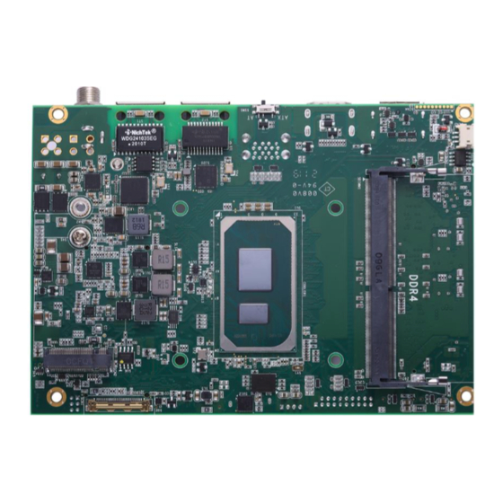
CAPA55R Capa Board Section 2 Board and Pin Assignments Board Dimensions and Fixing Holes Top View Board and Pin Assignments... - Page 12 CAPA55R Capa Board Bottom View Board and Pin Assignments...
- Page 13 CAPA55R Capa Board Side View Board and Pin Assignments...
-
Page 14: Board Layout
CAPA55R Capa Board Board Layout Top View Side View Board and Pin Assignments... - Page 15 CAPA55R Capa Board Bottom View Board and Pin Assignments...
-
Page 16: Installing Cooling Fan
CAPA55R Capa Board Installing Cooling Fan Image below illustrates how to install cooling fan on CAPA55R. Board and Pin Assignments... - Page 17 CAPA55R Capa Board Board and Pin Assignments...
- Page 18 CAPA55R Capa Board Board and Pin Assignments...
-
Page 19: Installing M.2 2230 Key E And M.2 2280 Key M
CAPA55R Capa Board Installing M.2 2230 Key E and M.2 2280 Key M Image below illustrates how to install M.2 2230 Key E (CN10) and M.2 2280 Key M (CN6). M.2 2230 Key E card only: M.2 2280 Key M card only: M.2 2230 Key E card + M.2 2280 Key M card:... -
Page 20: Jumper And Switch Settings
And remove jumper clip from 2 jumper pins to open. Below illustration shows how to set up jumper. Properly configure jumper and switch settings on the CAPA55R to meet your application purpose. Below you can find a summary table of jumper, switch and onboard default settings. -
Page 21: Lvds/Edp Voltage Selection (Jp1)
CAPA55R Capa Board 2.5.1 LVDS/eDP Voltage Selection (JP1) This is a 2x3-pin (pitch=2.0mm) jumper. The board supports voltage selection for flat panel displays. Use JP1 to set LVDS/eDP connector (CN3/SCN1) VCCM pin to +3.3V, +5V or +12V voltage level. To prevent hardware damage, before connecting please make sure that input voltage of the flat panel is correct. -
Page 22: Connectors
CAPA55R Capa Board Connectors Signals go to other parts of the system through connectors. Loose or improper connection might cause problems, please make sure all connectors are properly and firmly connected. Here is a summary table of connectors on the hardware. -
Page 23: Sata Power Connector (Cn1)
CAPA55R Capa Board 2.6.1 SATA Power Connector (CN1) This is a 4-pin (pitch=2mm) wafer connector, which is compliant with JST B4B-PH-K-S, for SATA power interface. Signal +12V 2.6.2 USB 3.2 Gen2 Wafer Connector (CN2) This is a 2x10 19-pin (pitch=2mm) wafer connector for installing versatile USB peripherals such as keyboard, mouse, scanner, etc.;... -
Page 24: Lvds Connector (Cn3)
CAPA55R Capa Board 2.6.3 LVDS Connector (CN3) This is a 2x20-pin (pitch=1.0mm) connector which is compliant with JST SM40B-SRDS-G-TF for LVDS LCD interface. It is strongly recommended to connect it with matching connector, SHDR-40VS-B. Pin 1~6 VCCM can be set to +3.3V, +5V or +12Vby setting JP1 (see section 2.5.1). - Page 25 CAPA55R Capa Board 24-bit single channel 18-bit dual channel Pin Signal Pin Signal Pin Signal Pin Signal VCCM VCCM VCCM VCCM VCCM VCCM VCCM VCCM VCCM VCCM VCCM VCCM 10 GND 10 GND 11 N.C 12 N.C 11 N.C 12 Channel B D0- 13 N.C...
-
Page 26: Usb 2.0 Wafer Connectors (Cn4 And Cn5)
CAPA55R Capa Board 2.6.4 USB 2.0 Wafer Connectors (CN4 and CN5) These are 2x5-pin (pitch=2mm) wafer connectors, which are compliant with Hirose DF11-XDP-2DSA, for installing versatile USB 2.0 compliant interface peripherals. CN4: Signal Signal USB VCC USB VCC (+5V_SBY) (+5V_SBY) -
Page 27: Key M Connector (Cn6)
CAPA55R Capa Board 2.6.5 M.2 Key M Connector (CN6) The CN6 is a M.2 2280 Key M connector recommended for installing storage card. Signal Signal +3.3V +3.3V PEG_PCIE_RX3_N PEG_PCIE_RX3_P PEG_PCIE_TX3_N +3.3V PEG_PCIE_TX3_P +3.3V +3.3V PEG_PCIE_RX2_N +3.3V PEG_PCIE_RX2_P PEG_PCIE_TX2_N PEG_PCIE_TX2_P PEG_PCIE_RX1_N... -
Page 28: Sim Card Wafer Connector (Cn7)
CAPA55R Capa Board 2.6.6 SIM Card Wafer Connector (CN7) The CN7 is a 6-pin (pitch=1.0mm) wafer connector, which is compliant with JST B6B-PH-K-S, for SIM Card interface. You are suggested to use AX93A19 for CN7 to have SIM card slot. -
Page 29: Key E Connector (Cn10)
CAPA55R Capa Board 2.6.9 M.2 Key E Connector (CN10) The CN10 is a M.2 2230 Key E connector. It is suggested to install the M.2 wireless module via PCIe x1 and USB 2.0 with 22mm width and 30mm length. Signal Signal +3.3V_SBY... -
Page 30: I 2 C Connector (Cn11)
CAPA55R Capa Board 2.6.10 C Connector (CN11) This is a 4-pin (pitch=1.25mm) connector for I C interface which is compatible with SMBus. Signal C _CLK C _DATD C _ALERT_N 2.6.11 Digital I/O Wafer Connector (CN12) This is a 1x10-pin (pitch=1.0mm) wafer connector fully compliant with JST BM10B-SRSS-TB. -
Page 31: Front Panel Connector (Cn14)
CAPA55R Capa Board 2.6.12 Front Panel Connector (CN14) This is a 2x6-pin header (pitch=2.0mm) for front panel interface. 8 10 12 Signal Signal BUZZER- BUZZER+ PWR_PSON 9 11 PWRLED- PWRLED+ PWRSW- PWRSW+ HW RST- HW RST+ HDDLED- HDDLED+ Internal Buzzer Pin 1(-) and 2(+) connect the internal buzzer cable. -
Page 32: Displayport++ Connector (Cn15)
CAPA55R Capa Board 2.6.13 DisplayPort++ Connector (CN15) The DisplayPort++ interface is available through connector CN15. Signal DP_LANE0P DP_LANE0_N DP_LANE1_P DP_LANE1_N DP_LANE2_P DP_LANE2_N DP_LANE3_P DP_LANE3_N Detect Pin DP_AUX_P DP_AUX_N DP_HPDE +3.3V 2.6.14 HDMI Connector (CN16) The HDMI (High-Definition Multimedia Interface) is a compact digital interface which is capable of transmitting high-definition video and high-resolution audio over a single cable. -
Page 33: Power Connector (Cn17/Atx1/Atx2)
CAPA55R Capa Board 2.6.15 Power Connector (CN17/ATX1/ATX2) Steady and sufficient power can be supplied to all components on the board by connecting the power connector. Please make sure all components and devices are properly installed before connecting the power connector. -
Page 34: Sata Connector (Sata1)
CAPA55R Capa Board 2.6.17 SATA Connector (SATA1) This Serial Advanced Technology Attachment (Serial ATA or SATA) connector is for high-speed SATA interface. It is a computer bus interface for connecting to devices such as hard disk drive. Signal SATA_0_TX_P SATA_0_TX_N... -
Page 35: Usb 3.2 Gen2 Type A Port (Cn13/Usb1)
CAPA55R Capa Board 2.6.19 USB 3.2 Gen2 Type A Port (CN13/USB1) The board comes with one Universal Serial Bus (compliant with USB 3.2 Gen 2 (10Gb/s)) ports on the rear I/O for installing USB peripherals such as keyboard, mouse, scanner, etc. -
Page 36: Edp Connector (Scn1)
CAPA55R Capa Board 2.6.21 eDP Connector (SCN1) The embedded DisplayPort (eDP) interface is available through 30-pin connector (IPEX-20453-030T-01), which is compliant with I-PEX-CABLINE II HT1 20143. Signal Signal VCC _BKLT VCC _BKLT VCC _BKLT VCC _BKLT BKLT_CTL BKLT_EN EMB_HPD BIST... -
Page 37: Key B Connector (Scn2)
CAPA55R Capa Board 2.6.22 M.2 Key B Connector (SCN2) The SCN2 is a M.2 Key B connector. It is suggested to install the M.2 storage module via SATA with 22mm width and 42mm length or the M.2 cellular module with 30mm width and 42mm length or 30mm width and 50/52mm length. -
Page 38: Fan Connector (Scn3)
CAPA55R Capa Board 2.6.23 Fan Connector (SCN3) This is a 3-pin (pitch=1.5mm) connector for fan interface. Signal +12V level Fan speed feedback Board and Pin Assignments... -
Page 39: Hardware Description
Make sure all correct settings are arranged for the installed microprocessor to prevent the CPU from damages. BIOS The CAPA55R uses AMI Plug and Play BIOS with a single 256Mbit SPI Flash. System Memory The CAPA55R supports two 260-pin DDR4 SO-DIMM sockets. The memory module comes in sizes of 4GB, 8GB and 16GB. -
Page 40: I/O Port Address Map
CAPA55R Capa Board I/O Port Address Map Hardware Description... -
Page 41: Interrupt Controller (Irq) Map
CAPA55R Capa Board Interrupt Controller (IRQ) Map The interrupt controller (IRQ) mapping list is shown as follows: Hardware Description... - Page 42 CAPA55R Capa Board Hardware Description...
- Page 43 CAPA55R Capa Board Hardware Description...
- Page 44 CAPA55R Capa Board Hardware Description...
- Page 45 CAPA55R Capa Board Hardware Description...
-
Page 46: Memory Map
CAPA55R Capa Board Memory Map The memory mapping list is shown as follows: Hardware Description... -
Page 47: Ami Bios Setup Utility
CAPA55R Capa Board Section 4 AMI BIOS Setup Utility The AMI UEFI BIOS provides users with a built-in setup program to modify basic system configuration. All configured parameters are stored in a flash chip to save the setup information whenever the power is turned off. This section provides users with detailed description about how to set up basic system configuration through the AMI BIOS setup utility. - Page 48 CAPA55R Capa Board Hot Keys Description → Left/Right The Left and Right <Arrow> keys allow you to select a setup screen. The Up and Down <Arrow> keys allow you to select a setup screen or Up/Down sub-screen. The Plus and Minus <Arrow> keys allow you to change the field value of a +−...
-
Page 49: Main Menu
CAPA55R Capa Board Main Menu When you first enter the setup utility, you will enter the Main setup screen. You can always return to the Main setup screen by selecting the Main tab. System Time/Date can be set up as described below. -
Page 50: Advanced Menu
CAPA55R Capa Board Advanced Menu The Advanced menu also allows users to set configuration of the CPU and other system devices. You can select any of the items in the left frame of the screen to go to the sub menus: ►... - Page 51 CAPA55R Capa Board ⚫ EC DIO Configuration You can use this screen to select options for the 8-bit Digital I/O Configuration. A description of the selected item appears on the right side of the screen. For items marked with “”, please press <Enter> for more options.
- Page 52 CAPA55R Capa Board If DIO Modification is disabled, you are not allowed to change inputs/outputs setting. If enabled, you can load manufacture default and access to the DIO status sub-screen to change input/output setting, see image below. The DIO status sub-screen is as follows:...
- Page 53 CAPA55R Capa Board ⚫ Serial Port Configuration You can use this screen to select options for serial port configuration, and change the value of the selected option. A description of the selected item appears on the right side of the screen. For items marked with “”, please press <Enter> for more options.
- Page 54 CAPA55R Capa Board ⚫ Serial Port 1 Configuration Serial Port Enable or disable serial port 1. The optimal setting for base I/O address is 248h and for interrupt request address is IRQ7. COM Port Type Use this item to set RS-232/422/485 communication mode.
- Page 55 CAPA55R Capa Board Terminal Mode Enable or disable the RS-422/485 termination resistor for enhancing the signal. ⚫ Serial Port 2 Configuration Serial Port Enable or disable serial port 2. The optimal setting for base I/O address is 258h and for interrupt request address is IRQ6.
- Page 56 CAPA55R Capa Board ⚫ Hardware Monitor This screen shows hardware health status. This screen displays the temperature of system and CPU, fan speed in RPM and system voltages (VBAT and +5V). Smart Fan Mode Select Set Smart Fan mode. The default is Auto Mode. In Auto Mode, the fan spins at different speed depending on system temperature;...
- Page 57 CAPA55R Capa Board ⚫ Trusted Computing You can use this screen for TPM (Trusted Platform Module) configuration. It also shows current TPM status information. Security Device Support Enable or disable BIOS support for security device. AMI BIOS Setup Utility...
- Page 58 CAPA55R Capa Board ⚫ CPU Configuration This screen shows the CPU Configuration. Hyper-Threading Enable or disable Hyper-Threading Technology. When enabled, it allows a single physical processor to multitask as multiple logical processors. When disabled, only one thread per enabled core is enabled.
- Page 59 CAPA55R Capa Board Turbo Mode Enable or disable Intel turbo boost mode allowing processor cores to run faster but not ® exceed CPU defined frequency limits. ⚫ Storage Configuration You can use this screen to select options for storage configuration, and change the value of the selected option.
- Page 60 CAPA55R Capa Board ⚫ SATA and RST Configuration During system boot up, BIOS automatically detects the presence of SATA devices. In the SATA and RST configuration menu, you can see hardware currently installed in the SATA port. SATA Controller(s) Enable or disable the SATA Controller feature.
- Page 61 CAPA55R Capa Board ⚫ NVMe Configuration If M.2 NVMe card is installed in M.2 Key M Connector (CN6) (see section 2.6.5), you will see related information and images given below. AMI BIOS Setup Utility...
- Page 62 CAPA55R Capa Board ⚫ AMT Configuration Use this screen to configure AMT parameters. AMT BIOS Features Enable or disable Active Management Technology BIOS features. ⚫ USB Configuration USB Devices Display all detected USB devices. AMI BIOS Setup Utility...
-
Page 63: Chipset Menu
CAPA55R Capa Board Chipset Menu The Chipset menu allows users to change the advanced chipset settings. ⚫ System Agent (SA) Configuration This screen allows users to configure System Agent (SA) parameters. LVDS Panel Device Enable or disable LVDS panel device. - Page 64 CAPA55R Capa Board LVDS Panel Type Select the appropriate LVDS panel resolution, see image below. HD Audio Control detection of the HD Audio device. Disabled: HDA will be unconditionally disabled. Enabled: HDA will be unconditionally enabled. AMI BIOS Setup Utility...
-
Page 65: Security Menu
CAPA55R Capa Board Security Menu The Security menu allows users to change the security settings for the system. ⚫ Administrator Password. Set administrator password. ⚫ User Password Set user password. AMI BIOS Setup Utility... -
Page 66: Boot Menu
CAPA55R Capa Board Boot Menu The Boot menu allows users to change boot options of the system. ⚫ Setup Prompt Timeout Number of seconds to wait for setup activation key. 65535(0xFFFF) means indefinite waiting. ⚫ Bootup NumLock State Use this item to select the power-on state for the keyboard NumLock. -
Page 67: Save & Exit Menu
CAPA55R Capa Board Save & Exit Menu The Save & Exit menu allows users to load your system configuration with optimal or fail-safe default values. ⚫ Save Changes and Exit When you have completed the system configuration changes, select this option to leave Setup and return to Main Menu. - Page 68 CAPA55R Capa Board ⚫ Discard Changes Select this option to quit Setup without making any permanent changes to the system configuration. Select Discard Changes from the Save & Exit menu and press <Enter>. Select Yes to discard changes. ⚫ Restore Defaults It automatically sets all Setup options to a complete set of default settings when you select this option.
-
Page 69: Appendix A Watchdog Timer
CAPA55R Capa Board Appendix A Watchdog Timer A.1 About Watchdog Timer After the system stops working for a while, it can be auto-reset by the watchdog timer. The integrated watchdog timer can be set up in the system reset mode by program. - Page 70 CAPA55R Capa Board This page is intentionally left blank. Watchdog Timer...
-
Page 71: Appendix B Digital I/O
CAPA55R Capa Board Appendix B Digital I/O B.1 About Digital I/O The onboard GPIO or digital I/O has 8 bits (DIO0~7). Each bit can be set to function as input or output by software programming. In default, all pins are pulled high with +5V level (according to main power). - Page 72 CAPA55R Capa Board #define DIO_PIN8 BIT7 //correspondence to HW pin is GPO3 void main() // BIT0-BIT3 is input, BIT4-BIT7 is output unsigned char DIO_DefaultInOutSetting = 0x0F; // BIT0-BIT3 is input so do not care, BIT4-BIT7 is High unsigned char DIO_DefaultHighLowSetting = 0xF0;...
-
Page 73: Appendix C Iamt Settings
CAPA55R Capa Board Appendix C iAMT Settings The Intel ® Active Management Technology (Intel ® iAMT) has decreased a major barrier to IT efficiency that uses built-in platform capabilities and popular third-party management and security applications to allow IT a better discovering, healing, and protection their networked computing assets. - Page 74 CAPA55R Capa Board You will be asked to change the password before setting ME. You must confirm your new password while revising. The new password must contain: (example: !!11qqQQ) (default value). ⚫ Eight characters ⚫ One upper case ⚫ One lower case ⚫...
-
Page 75: Iamt Configuration
CAPA55R Capa Board iAMT Configuration From Main Menu, select Intel ® Standard Manageability Configuration and press <Enter>. Set Manageability Feature Selection to Enabled. iAMT Settings... - Page 76 CAPA55R Capa Board ⚫ SOL/Storage Redirection/KVM This screen enabling disabling Serial-over-LAN (SOL)/Storage Redirection/Keyboard Video Mouse (KVM) functionality. ⚫ User Consent User Opt-in Configure this item when user consent should be required. Opt-in Configurable from Remote IT Enable or disable remote change capability of user consent feature.
- Page 77 CAPA55R Capa Board ⚫ Network Setup ® AMT Configuration Menu, select Network Setup. 1. From Intel 2. Select ME Network Name Settings to set computer host and domain name. iAMT Settings...
- Page 78 CAPA55R Capa Board 3. Select TCP/IP to get into Network interface. Get into DHCP Mode and set it to Disabled. iAMT Settings...
- Page 79 CAPA55R Capa Board 4. If DHCP Mode is disabled, set the following settings: ⚫ IP address ⚫ Subnet mask 5. Go back to Intel® iAMT Configuration, then select Activate Network Access and press <Enter>. 6. Exit from MEBx after completing the iAMT settings.
- Page 80 CAPA55R Capa Board ⚫ Remote Setup and Configuration 1. Select TLS PKI to get into remote configuration screen. Then select Start Configuration to activate it. iAMT Settings...
- Page 81 CAPA55R Capa Board 2. Select Manage Hashes to add, delete and activate hash. iAMT Settings...
- Page 82 CAPA55R Capa Board ⚫ Power Control AMT ON in Host Sleep States Select the appropriate AMT ON in Host Sleep States setting. Options are ON in S0 and ON in S0, ME Wake in S3, S4-5 (AC only). Idle Timeout This is timeout value for Wake_On_ME in minutes.
-
Page 83: Iamt Web Console
CAPA55R Capa Board iAMT Web Console From a web browser, please type http://(IP ADDRESS):16992, which connects to iAMT Web. Example: http://10.1.40.214:16992 To log on, you will be required to type in username and password for access to the Web. USER: admin (default value) - Page 84 CAPA55R Capa Board Enter the iAMT Web. Click Remote Control, and select commands on the right side. When you have finished using the iAMT Web console, close the Web browser. iAMT Settings...
Need help?
Do you have a question about the CAPA55R and is the answer not in the manual?
Questions and answers