
Related Manuals for AXIOMTEK SBC81203 Series


Summary of Contents for AXIOMTEK SBC81203 Series
- Page 1 SBC81203 Series ® ® Intel Core Duo/ Pentium ® ® Pentium 4/Celeron PICMG 1.0 Single Board Computer User’s Manual...
- Page 2 AXIOMTEK does not warrant or assume any legal liability or responsibility for the accuracy, completeness or usefulness of any information in this document. AXIOMTEK does not make any commitment to update the information in this manual.
- Page 3 Wear a wrist-grounding strap, available from most electronic component stores, when handling boards and components. Trademarks Acknowledgments AXIOMTEK is a trademark of AXIOMTEK Co., Ltd. ® Windows is a trademark of Microsoft Corporation. Phoenix & AWARD are trademarks of Phoenix Technology Ltd.
-
Page 4: Table Of Contents
Table of Contents Chapter 1 Introduction ..............1 1.1 Specifications................. 2 1.2 Utilities Supports ..............3 1.3 Block Diagram ............... 4 Chapter 2 Jumpers and Connectors..........5 2.1 Board Dimensions ..............5 2.2 Board Layout................6 2.3 Jumper Settings..............7 2.3.1 COM2 Mode Select Jumpers ......... - Page 5 5.5 Standard CMOS Setup Menu ..........30 5.6 Advanced BIOS Features ............ 33 5.7 Advanced Chipset Features ..........38 5.8 Integrated Peripherals ............39 5.9 Power Management Setup ..........43 5.10 PnP/PCI Configuration Setup ..........45 5.11 PC Health Status ............... 47 5.12 Frequency/Voltage Control ..........
- Page 6 MEMO...
-
Page 7: Chapter 1 Introduction
SBC81203 LGA775 SBC User’s Manual C h a p t e r 1 Introduction The SBC81203 PICMG 1.0 full-size Single Board Computer supports ® ® ® ® Intel Core 2 Duo, Pentium D, Pentium 4 and Celeron processors, at FSB 533/800/1066 MHz. The board integrates chipsets ®... -
Page 8: Specifications
SBC81203 LGA775 SBC User’s Manual Specifications ® ® ® CPU: Intel Core 2 Duo, Pentium D, Pentium 4 and ® Celeron D processors ® System Chipset: Intel 945G & ICH7R CPU Socket: LGA775 Front-Side Bus: 533/800/1066MHz BIOS Award PnP Flash BIOS System Memory Two x 240-pin DDR2 DIMM sockets Maximum up to 4GB DDR2 memory... -
Page 9: Utilities Supported
SBC81203 LGA775 SBC User’s Manual 10/100/1000Mb Dual PCI-Express LAN Wake On LAN support Serial ATA Built-in four SATA/SATA II ports onboard support the maximum transfer rate up to 300MB/sec Audio Realtek ALC203 Audio Codec onboard Hardware Monitoring Controller: Winbond W83627HF-AW detection of CPU temperature, system temperature, power failure and fan speed Watchdog Timer... -
Page 10: Block Diagram
SBC81203 LGA775 SBC User’s Manual Block Diagram I/O Bracket Introduction... -
Page 11: Chapter 2 Jumpers And Connectors
SBC81203 LGA775 SBC User’s Manual C h a p t e r 2 Jumpers and Connectors Board Dimensions Jumpers and Connectors... -
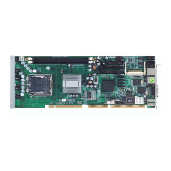
Page 12: Board Layout
SBC81203 LGA775 SBC User’s Manual Board Layout Jumpers and Connectors... -
Page 13: Jumper Settings
SBC81203 LGA775 SBC User’s Manual Jumper Settings Proper jumer settings configure the SBC81203 to meet your application purpose. 2.3.1 COM2 Mode Select Jumpers: JP4, JP5, JP6 These jumpers select the COM2 port’s communication mode to operate RS-232 or RS-422/485. Description Function Jumper Setting COM2 RS-232... -
Page 14: Cmos Clear Jumper
SBC81203 LGA775 SBC User’s Manual 2.3.2 CMOS Clear Jumper: JP15 You may need to use this jumper is to clear the CMOS memory if incorrect BIOS settings. Description Function Jumper Setting Normal CMOS Clear JP15 (Default) Clear JP15 CMOS Jumpers and Connectors... -
Page 15: Connectors
SBC81203 LGA775 SBC User’s Manual Connectors Connectors connect the CPU card with other parts of the system. Loose or improper connection might cause problems. Make sure all connectors are properly and firmly connected. Here is a summary table shows you all connectors on the board. Connectors Label Connectors... -
Page 16: Print Port Or Floppy Connector
SBC81203 LGA775 SBC User’s Manual 2.4.1 Print Port Connector: PRN1 Print Port Connector [Default] This board has a multi-mode parallel port to support: 1. Standard Mode: IBM PC/XT, PC/AT and PS/2™ are compatible with bi-directional parallel port. 2. Enhanced Mode: Enhance parallel port (EPP) is compatible with EPP 1.7 and EPP 1.9 (IEEE 1284 compliant). -
Page 17: Audio Connector
SBC81203 LGA775 SBC User’s Manual 2.4.2 Audio Connector: CN1 CN1 is a 10-pin connector to support the audio interface. Signal Signal MIC-IN 2 GND Line In L 4 GND Line In R 6 GND Audio Out L 8 GND Audio Out R 10 GND 2.4.3 Serial Port Interface Connectors: COM1, COM2 The serial interface for the board consists of COM1 port (COM1) and... -
Page 18: Floppy Disk Port Connector
SBC81203 LGA775 SBC User’s Manual Signal +12V +12V 2.4.5 Floppy Disk Port Connector: FDD1 The board provides a 34-pin header type connector, FDD1, supporting up to two floppy drives. The floppy drives may be any one of the following types: 5.25" 360KB/1.2MB and 3.5" 720KB/1.44MB/2.88MB. Signal Signal Signal... -
Page 19: Parallel Ide Interface Connector
SBC81203 LGA775 SBC User’s Manual 2.4.6 Parallel IDE Interface Connector: IDE1 The board provided one IDE Port to support maximum up to two IDE devices. Description Description Description Reset # Data 7 Data 8 Data 6 Data 9 Data 5 Data 10 Data 4 Data 11... -
Page 20: Sata Connectors
SBC81203 LGA775 SBC User’s Manual 2.4.7 SATA Connectors: SATA1~4 These SATA connectors are for high-speed SATA interface ports and they can be connected to hard disk devices. Signal SATA1~4 SATA_TX+ SATA_TX- SATA_RX- SATA_RX+ 2.4.8 USB Connectors: USB1~2 These Universal Serial Bus (USB) connectors on this board are for installing versatile USB interface peripherals. -
Page 21: Front Panel Connector
SBC81203 LGA775 SBC User’s Manual 2.4.9 Front Panel Connector: CN5 Power LED Pins 1, 3, 5 connect the system power LED indicator to its respective switch on the case. Pin 1 is +, and pin 5 assigned to -. Pin 3 is defined as NC. -
Page 22: Axiom Acpi Connector
SBC81203 LGA775 SBC User’s Manual 2.4.10 AXIOM ACPI Connector: CN4 It is to support remote power on/off for turning off the system through software control while using the ATX-compliant power supply. Signal Signal EXTSMI POWER BUTTOM SUSB +5VSB 2.4.11 Internal Mouse/Keyboard Connector: MS1/KB1 The board provides a keyboard (KB1) and Mouse (MS1) interface with two 5-pin connectors. - Page 23 SBC81203 LGA775 SBC User’s Manual MEMO Jumpers and Connectors...
-
Page 24: Chapter 3 Installation
SBC81203 LGA775 SBC User’s Manual C h a p t e r 3 Hardware Installation ® Before installing the processor, please access Intel website for more detailed information http://www.intel.com Installing the Processor The LGA775 processor socket comes with a cover to protect the processor. - Page 25 SBC81203 LGA775 SBC User’s Manual Open the cover (C), you can Be careful not to touch the see the contact. contact (D). Remove the plastic cap (E) from the cover. Hardware Installation...
- Page 26 SBC81203 LGA775 SBC User’s Manual Place the CPU down into the socket. Be careful not to touch the contact. Hold the edges of the CPU, and orientate it as the marked direction (G) down into the socket to match the (H) and (F) locations. Hardware Installation...
- Page 27 SBC81203 LGA775 SBC User’s Manual Slightly push down the cover and hook the lever (I~J). The CPU is completely locked. Orientate the CPU cooling fan to fixing holes on the board. Hardware Installation...
- Page 28 SBC81203 LGA775 SBC User’s Manual Screw the CPU cooling fan onto the board. Make sure the CPU fan is plugged to the CPU fan connector. Hardware Installation...
-
Page 29: Installing The Memory
SBC81203 LGA775 SBC User’s Manual Installing the Memory The board supports two 240-pin DDR2 DIMM memory sockets with maximum memory capacity up to 4GB. Please follow steps below to install the memory modules: Push down latches on each side of the DIMM socket. Align the memory module with the socket that notches of memory module must match the socket keys for a correct intallation. -
Page 30: Chapter 4 Hardware Description
CPU from damages. BIOS The SBC81203 Series uses Award Plug and Play BIOS with a single 4Mbit Flash EPROM. System Memory The SBC81203 Series industrial CPU card supports two 240-pin DDR2 DIMM sockets for a maximum memory of 4GB DDR2 SDRAMs. -
Page 31: I/O Port Address Map
SBC81203 LGA775 SBC User’s Manual I/O Port Address Map ® ® ® ® The Intel Core 2 Duo, Pentium D, Pentium 4 and Celeron CPUs can communicate via I/O ports. There are total 1KB port addresses available for assignment to other devices via I/O expansion cards. -
Page 32: Chapter 5 Award Bios Utility
SBC81203 LGA775 SBC User’s Manual C h a p t e r 5 Award BIOS Utility The Phoenix-Award BIOS provides users with a built-in Setup program to modify basic system configuration. All configured parameters are stored in a battery-backed-up RAM (CMOS RAM) to save the Setup information whenever the power is turned off. -
Page 33: Control Keys
SBC81203 LGA775 SBC User’s Manual Control Keys Move cursor to the previous item Up arrow Move cursor to the next item Down arrow Move cursor to the item on the left hand Left arrow Move to the item in the right hand Right arrow Main Menu -- Quit and delete changes into CMOS Status Page Setup Menu and Option Page Setup... -
Page 34: The Main Menu
SBC81203 LGA775 SBC User’s Manual The Main Menu Once you enter the Award BIOS CMOS Setup Utility, the Main Menu appears on the screen. In the Main Menu, there are several Setup functions and a couple of Exit options for your selection. Use arrow keys to select the Setup Page you intend to configure then press <Enter>... -
Page 35: Standard Cmos Setup Menu
SBC81203 LGA775 SBC User’s Manual Standard CMOS Setup Menu The Standard CMOS Setup Menu displays basic information about your system. Use arrow keys to highlight each item, and use <PgUp> or <PgDn> key to select the value you want in each item. Date The date format is <day>, <date>... - Page 36 SBC81203 LGA775 SBC User’s Manual IDE Channel 0 Master/IDE Channel 0 Slave/IDE Channel 1 Master/IDE Channel 1 Slave These items identify the types of each IDE channel installed in the computer. There are 45 predefined types (Type 1 to Type 45) and 2 user’s definable types (Type User) for Enhanced IDE BIOS.
- Page 37 SBC81203 LGA775 SBC User’s Manual Halt On This item determines whether the system will halt or not, if an error is detected while powering up. The system booting will halt on any errors No errors detected. (default) Whenever BIOS detects a non-fatal error, the All errors system will stop and you will be prompted.
-
Page 38: Advanced Bios Features
SBC81203 LGA775 SBC User’s Manual Advanced BIOS Features This section allows you to configure and improve your system, to set up some system features according to your preference. CPU Feature Scroll to this item and press <Enter> to view the CPU Feature sub menu. - Page 39 SBC81203 LGA775 SBC User’s Manual Hard Disk Boot Priority Scroll to this item and press <Enter> to view the sub menu to decide the disk boot priority. Press <Esc> to return to the Advanced BIOS Features page. CD-ROM Boot Priority Scroll to this item and press <Enter>...
- Page 40 SBC81203 LGA775 SBC User’s Manual Virus Warning This option flashes on the screen. During and after the system boot up, any attempt to write to the boot sector or partition table of the hard disk drive will halt the system with the following message. You can run an anti-virus program to locate the problem.
- Page 41 SBC81203 LGA775 SBC User’s Manual Enabled Enable Quick POST Normal POST Disabled First/Second/Third Boot Device These items let you select the 1 , and 3 devices that the system will search for during its boot-up sequence. The wide range of selection includes Floppy, LS120, ZIP100, HDD0~3, SCSI, and CDROM.
- Page 42 SBC81203 LGA775 SBC User’s Manual If a wrong password is entered at the prompt, the system System will not boot, the access to Setup will be denied, either. If a wrong password is entered at the prompt, the system Setup will boot, but the access to Setup will be denied.
-
Page 43: Advanced Chipset Features
SBC81203 LGA775 SBC User’s Manual Advanced Chipset Features This section contains completely optimized chipset’s features on the board that you are strongly recommended to leave all items on this page at their default values unless you are very familiar with the technical specifications of your system hardware. -
Page 44: Integrated Peripherals
SBC81203 LGA775 SBC User’s Manual Integrated Peripherals This section allows you to configure your SuperIO Device, IDE Function and Onboard Device. OnChip IDE Device Scroll to this item and press <Enter> to view the sub menu OnChip IDE Device. IDE HDD Block Mode Block mode is also called block transfer, multiple commands, or multiple sector read/write. - Page 45 SBC81203 LGA775 SBC User’s Manual IDE DMA transfer access Automatic data transfer between system memory and IDE device with minimum CPU intervention. This improves data throughput and frees CPU to perform other tasks. On-Chip Primary/Secondary PCI IDE The integrated peripheral controller contains an IDE interface with support for two IDE channels.
- Page 46 SBC81203 LGA775 SBC User’s Manual SATA Port If the “PATA IDE Mode“ is Primary, it will show ” P1, P3 is Secondary” which means SATA 2 and SATA 4 are Secondary. If the “PATA IDE Mode “ is Secondary, it will show “ P0, P2 is Primary “...
- Page 47 SBC81203 LGA775 SBC User’s Manual Super IO Device Scroll to this item and press <Enter> to view the sub menu Super IO Device. Onboard FDC Controller Select Enabled, if your system has a floppy disk controller (FDC) installed on the system board and you want to use it. If you install and-in FDC or the system has no floppy drive, select Disabled in this field.
-
Page 48: Power Management Setup
SBC81203 LGA775 SBC User’s Manual PWRON After PWR-Fail This item enables your computer to automatically restart or return to its operating status. Press <Esc> to return to the Integrated Peripherals page. Power Management Setup The Power Management Setup allows you to save energy of your system effectively. - Page 49 SBC81203 LGA775 SBC User’s Manual applications/files is saved to main memory that remains powered while most other hardware components turn off to save energy. The information stored in memory will be used to restore the system when a “wake up” event occurs. Power Management This option allows you to select the type of power Management.
-
Page 50: Pnp/Pci Configuration Setup
SBC81203 LGA775 SBC User’s Manual Soft-Off by PWR-BTTN This option only works with systems using an ATX power supply. It also allows users to define which type of soft power OFF sequence the system will follow. The default value is “Instant-Off”. This option follows the conventional manner of system performance when turning the power to OFF. - Page 51 SBC81203 LGA775 SBC User’s Manual Init Display First This item allows you to decide whether PCI Slot or AGP to be the first primary display card. Reset Configuration Data Normally, you leave this item Disabled. Select Enabled to reset Extended System Configuration Data (ESCD) when you exit Setup or if installing a new add-on cause the system reconfiguration a serious conflict that the operating system can not boot.
-
Page 52: Pc Health Status
SBC81203 LGA775 SBC User’s Manual ** PCI Express relative items ** Maximum Payload Size When using DDR SDRAM and Buffer size selection, another consideration in designing a payload memory is the size of the buffer for data storage. Maximum Payload Size defines the maximum TLP (Transaction Layer Packet) data payload size for the device. -
Page 53: Frequency/Voltage Control
SBC81203 LGA775 SBC User’s Manual Current SYSTEM FAN2 Speed Show you the current system fan1 temperature. Vcore +3.3V/+5V/+12V/VBAT(V)/5VSB Show you the voltage of +3.3V/+5V/+12V. 5.12 Frequency/Voltage Control This section is to control the CPU frequency and Supply Voltage, DIMM OverVoltage and AGP voltage. CPU Clock Ratio Use this item to select the CPU’s frequency. -
Page 54: Load Optimized Defaults
SBC81203 LGA775 SBC User’s Manual 5.13 Load Optimized Defaults This option allows you to load your system configuration with default values. These default settings are optimized to enable high performance features. To load CMOS SRAM with SETUP default values, please enter “Y”. If not, please enter “N”. -
Page 55: Set Supervisor/User Password
SBC81203 LGA775 SBC User’s Manual 5.14 Set Supervisor/User Password You can set a supervisor or user password, or both of them. The differences between them are: Supervisor password: You can enter and change the options on the setup menu. User password: You can just enter, but have no right to change the options on the setup menu. -
Page 56: Save & Exit Setup
SBC81203 LGA775 SBC User’s Manual 5.15 Save & Exit Setup This section allows you to determine whether or not to accept your modifications. Type “Y” to quit the setup utility and save all changes into the CMOS memory. Type “N” to bring you back to the Setup utility. Award BIOS Utility... -
Page 57: Exit Without Saving
SBC81203 LGA775 SBC User’s Manual 5.16 Exit Without Saving Select this option to exit the Setup utility without saving changes you have made in this session. Type “Y”, and it will quit the Setup utility without saving your modifications. Type “N” to return to the Setup utility. Award BIOS Utility... -
Page 58: Chapter 6 Installation Of Drivers
Installation of Drivers The device drivers are located on the Product Information CD-ROM that comes with the SBC81203 Series package. The auto-run function of drivers will guide you to install the utilities and device drivers under a Windows system. You can follow the onscreen instructions to install... - Page 59 SBC81203 LGA775 SBC User’s Manual ® An Intel License Agreement appears to show you the important information. Click “Yes” to next step. Please wait while running the following setup operations. Installation of Drivers...
- Page 60 SBC81203 LGA775 SBC User’s Manual Click “Finish” to complete the setup process. Instalation of Drivers...
-
Page 61: Installing Vga Driver
SBC81203 LGA775 SBC User’s Manual You will be asked to reboot your computer when the installation is completed. Please click “Yes, I want to restart my computer now” if you don’t need to install any other drivers. Otherwise, please click “No, I will restart my computer later”, and go on next step. - Page 62 SBC81203 LGA775 SBC User’s Manual ® An Intel License Agreement appears to show you the important information. Click “Yes” to next step. The message of Readme File Information appears to show you the system requirements and installation information. Please click “Next”. Instalation of Drivers...
- Page 63 SBC81203 LGA775 SBC User’s Manual 4. Please wait while running the following setup operations. 5. When this message appears, please click “Next”. Installation of Drivers...
- Page 64 SBC81203 LGA775 SBC User’s Manual 6. You will be asked to reboot your computer when the installation is completed. Please click “Yes, I want to restart my computer now” if you don’t need to install any other drivers. Otherwise, please click “No, I will restart my computer later”, and click “Finish”...
-
Page 65: Installing Lan Driver
SBC81203 LGA775 SBC User’s Manual Installing LAN Driver Run the InstallShield Wizard for Ethernet from the driver directory in your driver CD. Click “Next” to next step. Click “Install” to start the installation. Installation of Drivers... - Page 66 SBC81203 LGA775 SBC User’s Manual Please wait while running the following installation operation. Click “Finish” to complete the installation. Instalation of Drivers...
-
Page 67: Installing Audio Driver
SBC81203 LGA775 SBC User’s Manual Installing Audio Driver 1. Run the InstallShield Wizard program from the driver directory in your driver CD. Please wait while running the following operation. 2. When this message appears, please click “Next”. Installation of Drivers... - Page 68 SBC81203 LGA775 SBC User’s Manual 3. You will be asked to reboot your computer when the InstallShield Wizard is installed. Please click “Yes, I want to restart my computer now” or “No, I will restart my computer later”, and next click “Finish” to complete the installation. Instalation of Drivers...
- Page 69 SBC81203 LGA775 SBC User’s Manual MEMO Installation of Drivers...
-
Page 70: Appendix A Watch Dog Timer
SBC81203 LGA775 SBC User’s Manual A p p e n d i x A Watch Dog Timer Please follow the below WDT process for setup the WDT function. Watch Dog Timer... - Page 71 SBC81203 LGA775 SBC User’s Manual MEMO Watch Dog Timer...
-
Page 72: Appendix Bpci Irq Routing
SBC81203 LGA775 SBC User’s Manual A p p e n d i x B PCI IRQ Routing Digital I/O Software Programming PICMG PCI IRQ Routing Device Slot PCI Slot 0 BCDA PCI Slot 1 CDAB PCI Slot 2 DABC PCI Slot 3 ABCD On Board Device IRQ Routing Device... - Page 73 SBC81203 LGA775 SBC User’s Manual MEMO PCI IRQ Routing...
-
Page 74: Appendix C What Is Sata Raid Function
SBC81203 LGA775 SBC User’s Manual A p p e n d i x C What Is SATA RAID Function? Introduction ICH7R supports the SATA RAID function that allows you to combine four SATA-II disk drives into RAID volume configurations. The RAID configurations help you increase disk access speed (RAID0), or withstand a single disk drive failure (RAID1 or RAID5) and thus protect your data. - Page 75 SBC81203 LGA775 SBC User’s Manual 2. RAID1 (Mirroring) 3. RAID5 (Block Interleaved Distributed Parity) What Is SATA RAID Function...
-
Page 76: Appendix D Memory I/O Address
SBC81203 LGA775 SBC User’s Manual A p p e n d i x D Memory I/O Address Memory I/O Address... - Page 77 SBC81203 LGA775 SBC User’s Manual MEMO Memory I/O Address...
Need help?
Do you have a question about the SBC81203 Series and is the answer not in the manual?
Questions and answers