
Related Manuals for AXIOMTEK SBC81205


Summary of Contents for AXIOMTEK SBC81205
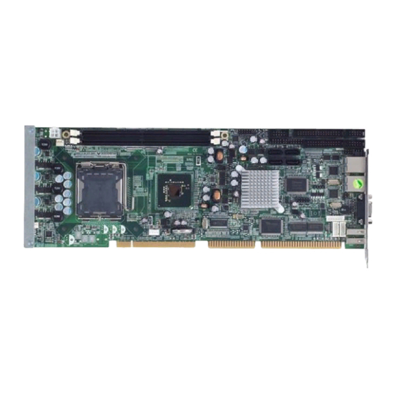
- Page 1 SBC81205 Series ® Intel Core 2 Quad/Core 2 Duo/ ® Celeron PICMG 1.0 Single Board Computer User’s Manual...
- Page 2 AXIOMTEK does not warrant or assume any legal liability or responsibility for the accuracy, completeness or usefulness of any information in this document. AXIOMTEK does not make any commitment to update the information in this manual.
-
Page 3: Esd Precautions
Wear a wrist-grounding strap, available from most electronic component stores, when handling boards and components. Trademarks Acknowledgments AXIOMTEK is a trademark of AXIOMTEK Co., Ltd. ® Windows is a trademark of Microsoft Corporation. Phoenix & AWARD are trademarks of Phoenix Technology Ltd. -
Page 4: Table Of Contents
Table of Contents Disclaimers ......................ii ESD Precautions ....................iii Chapter 1 Introduction ..............1 Specifications ..................2 Utilities Supported ................... 3 I/O Bracket ....................4 Chapter 2 Jumpers and Connectors ..........5 Board Layout ................... 5 Jumper Settings ..................6 2.2.1 COM2 Mode Select Jumpers ............ - Page 5 5.12 Frequency/Voltage Control..............46 5.13 Load Optimized Defaults ............... 47 5.14 Set Supervisor/User Password ............. 48 5.15 Save & Exit Setup ................. 49 5.16 Exit Without Saving ................50 Chapter 6 Installation of Drivers ..........51 Installing Chipset Driver ................ 51 Installing VGA Driver ................
- Page 6 MEMO...
-
Page 7: Chapter 1 Introduction
SBC81205 Core™ 2 Quad SBC User’s Manual C h a p t e r 1 Introduction The SBC81205 PICMG 1.0 full-size Single Board Computer supports ® ® Intel Core 2 Quad, Core 2 Duoand Celeron processors, at FSB ® 800/1066/1333 MHz. The board integrates chipsets Intel... -
Page 8: Specifications
SBC81205 Core™ 2 Quad SBC User’s Manual Specifications ® ® CPU: Intel Core 2 Quad, Core 2 Duoand Celeron processors ® System Chipset: Intel Q35 & ICH9/ICH9R CPU Socket: LGA775 Front-Side Bus: 800/1066/1333 MHz BIOS Phoenix-Award PnP Flash BIOS System Memory... -
Page 9: Utilities Supported
SBC81205 Core™ 2 Quad SBC User’s Manual Hardware Monitoring Controller: Winbond W83627DHG detection of CPU temperature, system temperature, power failure and fan speed Watchdog Timer Software programmable time interval and hardware reset only. 1~255 seconds; up to 255 levels Dimensions: 338 x 126 mm (6 layer) NOTE All specifications and images are subject to change without notice. -
Page 10: I/O Bracket
SBC81205 Core™ 2 Quad SBC User’s Manual I/O Bracket Introduction... -
Page 11: Chapter 2 Jumpers And Connectors
SBC81205 Core™ 2 Quad SBC User’s Manual C h a p t e r 2 Jumpers and Connectors Board Layout Jumpers and Connectors... -
Page 12: Jumper Settings
SBC81205 Core™ 2 Quad SBC User’s Manual Jumper Settings Proper jumer settings configure the SBC81205 to meet your application purpose. 2.2.1 COM2 Mode Select Jumpers (JP1, JP2, JP3) These jumpers select the COM2 port’s communication mode to operate RS-232 or RS-422/485. -
Page 13: Cmos Clear Jumper
SBC81205 Core™ 2 Quad SBC User’s Manual 2.2.2 CMOS Clear Jumper (JP5) You may need to use this jumper is to clear the CMOS memory if incorrect BIOS settings. Description Function Jumper Setting Normal CMOS Clear (Default) Clear CMOS 2.2.3 ATX Auto Power On/Off (JP7) When Jumper JP7 is set OPEN for AC power input, the system will be automatically power ON without pressing soft power button;... -
Page 14: Connectors
SBC81205 Core™ 2 Quad SBC User’s Manual Connectors Connectors connect the CPU card with other parts of the system. Loose or improper connection might cause problems. Make sure all connectors are properly and firmly connected. Here is a summary table shows you all connectors on the board. -
Page 15: Print Port Connector
SBC81205 Core™ 2 Quad SBC User’s Manual 2.3.1 Print Port Connector (PRN1) Print Port Connector [Default] This board has a multi-mode parallel port to support: 1. Standard Mode: IBM PC/XT, PC/AT and PS/2™ are compatible with bi-directional parallel port. 2. Enhanced Mode: Enhance parallel port (EPP) is compatible with EPP 1.7 and EPP 1.9... -
Page 16: Serial Port Interface Connectors
SBC81205 Core™ 2 Quad SBC User’s Manual 2.3.2 Serial Port Interface Connectors (COM1, COM2) The serial interface for the board consists of COM1 port (COM1) and COM2 (COM2) supports RS-232/RS-422/RS-485. Signal Signal COM1, COM2 Data Carrier Detect Data Set Ready (DSR) -
Page 17: Floppy Disk Port Connector
SBC81205 Core™ 2 Quad SBC User’s Manual 2.3.4 Floppy Disk Port Connector (FDD1) The board provides a 34-pin header type connector, FDD1, supporting up to two floppy drives. The floppy drives may be any one of the following types: 5.25" 360KB/1.2MB and 3.5" 720KB/1.44MB/2.88MB. -
Page 18: Sata Connectors
SBC81205 Core™ 2 Quad SBC User’s Manual 2.3.5 SATA Connectors (SATA1~4) These SATA connectors are for high-speed SATA interface ports and they can be connected to hard disk devices. Signal SATA1~4 SATA_TX+ SATA_TX- SATA_RX- SATA_RX+ 2.3.6 USB Connectors (USB3~4) These Universal Serial Bus (USB) connectors on this board are for installing versatile USB interface peripherals. -
Page 19: Front Panel Connector
SBC81205 Core™ 2 Quad SBC User’s Manual 2.3.7 Front Panel Connector (CN1) Power LED Pins 1, 3, 5 connect the system power LED indicator to its respective switch on the case. Pin 1 is +, and pin 5 assigned to -. -
Page 20: Axiom Acpi Connector
SBC81205 Core™ 2 Quad SBC User’s Manual 2.3.8 AXIOMTEK ACPI Connector (CN2) It is to support remote power on/off for turning off the system through software control while using the ATX-compliant power supply. Signal Signal EXTSMI POWER BUTTOM SUSB +5VSB 2.3.9 Internal Mouse/Keyboard Connector (MS1/KB1) -
Page 21: Chapter 3 Hardware Installation
SBC81205 Core™ 2 Quad SBC User’s Manual C h a p t e r 3 Hardware Installation ® Before installing the processor, please access Intel website for more detailed information http://www.intel.com Installing the Processor The LGA775 processor socket comes with a cover to protect the processor. - Page 22 SBC81205 Core™ 2 Quad SBC User’s Manual Open the cover (C), you can Be careful not to touch the see the contact. contact (D). Remove the plastic cap (E) from the cover. Hardware Installation...
- Page 23 SBC81205 Core™ 2 Quad SBC User’s Manual Place the CPU down into the socket. Be careful not to touch the contact. Hold the edges of the CPU, and orientate it as the marked direction (G) down into the socket to match the (H) and (F) locations.
- Page 24 SBC81205 Core™ 2 Quad SBC User’s Manual Slightly push down the cover and hook the lever (I~J). The CPU is completely locked. Orientate the CPU cooling fan to fixing holes on the board. Hardware Installation...
- Page 25 SBC81205 Core™ 2 Quad SBC User’s Manual Screw the CPU cooling fan onto the board. Make sure the CPU fan is plugged to the CPU fan connector. Hardware Installation...
-
Page 26: Installing The Memory
SBC81205 Core™ 2 Quad SBC User’s Manual Installing the Memory The board supports two 240-pin DDR2 DIMM memory sockets with maximum memory capacity up to 4 GB. Please follow steps below to install the memory modules: Push down latches on each side of the DIMM socket. -
Page 27: Chapter 4 Hardware Description
Make sure your installed microprocessor with all correct settings that prevents the CPU from damages. BIOS The SBC81205 Series uses Phoenix-Award Plug and Play BIOS with a single 4Mbit Flash. System Memory The SBC81205 Series industrial CPU card supports two 240-pin DDR2 DIMM sockets for a maximum memory of 4 GB DDR2 SDRAMs. -
Page 28: I/O Port Address Map
SBC81205 Core™ 2 Quad SBC User’s Manual I/O Port Address Map ® ® ® The Intel Core 2 Quad, Core 2 Duo, Pentium D, Pentium ® and Celeron D CPUs can communicate via I/O ports. There are total 1KB port addresses available for assignment to other devices via I/O expansion cards. -
Page 29: Chapter 5 Phoenix-Award Bios Utility
SBC81205 Core™ 2 Quad SBC User’s Manual C h a p t e r 5 Phoenix-Award BIOS Utility The Phoenix-Award BIOS provides users with a built-in Setup program to modify basic system configuration. All configured parameters are stored in a battery-backed-up RAM (CMOS RAM) to save the Setup information whenever the power is turned off. -
Page 30: Control Keys
SBC81205 Core™ 2 Quad SBC User’s Manual Control Keys Move cursor to the previous item Up arrow Move cursor to the next item Down arrow Move cursor to the item on the left hand Left arrow Move to the item in the right hand... -
Page 31: The Main Menu
SBC81205 Core™ 2 Quad SBC User’s Manual The Main Menu Once you enter the Phoenix-Award BIOS CMOS Setup Utility, the Main Menu appears on the screen. In the Main Menu, there are several Setup functions and a couple of Exit options for your selection. Use arrow keys to select the Setup Page you intend to configure then press <Enter>... -
Page 32: Standard Cmos Setup Menu
SBC81205 Core™ 2 Quad SBC User’s Manual Standard CMOS Setup Menu The Standard CMOS Setup Menu displays basic information about your system. Use arrow keys to highlight each item, and use <PgUp> or <PgDn> key to select the value you want in each item. - Page 33 SBC81205 Core™ 2 Quad SBC User’s Manual IDE Channel 0 Master/IDE Channel 0 Slave/IDE Channel 1 Master/IDE Channel 1 Slave These items identify the types of each IDE channel installed in the computer. There are 45 predefined types (Type 1 to Type 45) and 2 user’s definable types (Type User) for Enhanced IDE BIOS.
- Page 34 SBC81205 Core™ 2 Quad SBC User’s Manual Halt On This item determines whether the system will halt or not, if an error is detected while powering up. The system booting will halt on any errors detected. No errors (default) Whenever BIOS detects a non-fatal error, the All errors system will stop and you will be prompted.
-
Page 35: Advanced Bios Features
SBC81205 Core™ 2 Quad SBC User’s Manual Advanced BIOS Features This section allows you to configure and improve your system, to set up some system features according to your preference. CPU Feature Scroll to this item and press <Enter> to view the CPU Feature sub menu. - Page 36 SBC81205 Core™ 2 Quad SBC User’s Manual Hard Disk Boot Priority Scroll to this item and press <Enter> to view the sub menu to decide the disk boot priority. Press <Esc> to return to the Advanced BIOS Features page. CD-ROM Boot Priority Scroll to this item and press <Enter>...
- Page 37 SBC81205 Core™ 2 Quad SBC User’s Manual Virus Warning This option flashes on the screen. During and after the system boot up, any attempt to write to the boot sector or partition table of the hard disk drive will halt the system with the following message. You can run an anti-virus program to locate the problem.
- Page 38 SBC81205 Core™ 2 Quad SBC User’s Manual Enabled Enable Quick POST Disabled Normal POST First/Second/Third Boot Device These items let you select the 1 , and 3 devices that the system will search for during its boot-up sequence. The wide range of selection includes Floppy, LS120, ZIP100, HDD0~3, SCSI, and CDROM.
- Page 39 SBC81205 Core™ 2 Quad SBC User’s Manual If a wrong password is entered at the prompt, the system System will not boot, the access to Setup will be denied, either. If a wrong password is entered at the prompt, the system Setup will boot, but the access to Setup will be denied.
-
Page 40: Advanced Chipset Features
SBC81205 Core™ 2 Quad SBC User’s Manual Advanced Chipset Features This section contains completely optimized chipset’s features on the board that you are strongly recommended to leave all items on this page at their default values unless you are very familiar with the technical specifications of your system hardware. - Page 41 SBC81205 Core™ 2 Quad SBC User’s Manual PCI Express Root Port Func. Scroll to this item and press <Enter> to view the sub menu to decide the PCI Express Port. Press <Esc> to return to the Advanced Chipset Features page.
-
Page 42: Integrated Peripherals
SBC81205 Core™ 2 Quad SBC User’s Manual Integrated Peripherals This section allows you to configure your SuperIO Device, IDE Function and Onboard Device. OnChip IDE Device Scroll to this item and press <Enter> to view the sub menu OnChip IDE Device. - Page 43 SBC81205 Core™ 2 Quad SBC User’s Manual IDE DMA transfer access Automatic data transfer between system memory and IDE device with minimum CPU intervention. This improves data throughput and frees CPU to perform other tasks. IDE Master/Slave PIO The four IDE PIO (Programmed Input/Output) fields let you set a PIO mode (0-4) for each of the four IDE devices that the onboard IDE interface supports.
- Page 44 SBC81205 Core™ 2 Quad SBC User’s Manual USB 2.0 Controller Enable this item if you are using the EHCI (USB2.0) controller in the system. USB Keyboard Support Enable this item if the system has a Universal Serial Bus (USB) controller, and you have a USB keyboard.
- Page 45 SBC81205 Core™ 2 Quad SBC User’s Manual onboard parallel port. Options: 378H/IRQ7, 278H/IRQ5, 3BC/IRQ7 and Disabled. Parallel Port Mode Select an operating mode for the onboard parallel (printer) port. Select Normal unless your hardware and software require another mode in this field. Options: EPP1.9, ECP, SPP, ECPEPP1.7, EPP1.7.
-
Page 46: Power Management Setup
SBC81205 Core™ 2 Quad SBC User’s Manual Press <Esc> to return to the Main Menu page. Power Management Setup The Power Management Setup allows you to save energy of your system effectively. It will shut down the hard disk and turn OFF video display after a period of inactivity. - Page 47 SBC81205 Core™ 2 Quad SBC User’s Manual Power Management This option allows you to select the type (or degree) of power saving for Doze, Standby, and Suspend modes. The table below describes each power management mode: It is maximum power savings, only available for SL Max Saving CPUs.
- Page 48 SBC81205 Core™ 2 Quad SBC User’s Manual HDD Power Down If HDD activity is not detected for the length of time specified in this field, the hard disk drive will be powered down while all other devices remain active. Soft-Off by PWR-BTTN This option only works with systems using an ATX power supply.
-
Page 49: Pnp/Pci Configuration Setup
SBC81205 Core™ 2 Quad SBC User’s Manual 5.10 PnP/PCI Configuration Setup This section describes the configuration of PCI (Personal Computer Interconnect) bus system, which allows I/O devices to operate at speeds close to the CPU speed while communicating with other important components. - Page 50 SBC81205 Core™ 2 Quad SBC User’s Manual IRQ Resources When resources are controlled manually, assign each system interrupt to one of the following types in accordance with the type of devices using the interrupt: 1. Legacy ISA Devices compliant with the original PC AT bus...
-
Page 51: Pc Health Status
SBC81205 Core™ 2 Quad SBC User’s Manual 5.11 PC Health Status This section supports hardware monitering that lets you monitor those parameters for critical voltages, temperatures and fan speed of the board. Current SYSTEM Temperature Show you the current system1 temperature. -
Page 52: Frequency/Voltage Control
SBC81205 Core™ 2 Quad SBC User’s Manual 5.12 Frequency/Voltage Control This section is to control the CPU frequency and Supply Voltage, DIMM OverVoltage and PCI EXPRESS X16 voltage. CPU Clock Ratio Unlock Use this item to unlock CPU multiplier. CPU Clock Ratio Use this item to select the CPU’s frequency. -
Page 53: Load Optimized Defaults
SBC81205 Core™ 2 Quad SBC User’s Manual 5.13 Load Optimized Defaults This option allows you to load your system configuration with default values. These default settings are optimized to enable high performance features. To load CMOS SRAM with SETUP default values, please enter “Y”. If not, please enter “N”. -
Page 54: Set Supervisor/User Password
SBC81205 Core™ 2 Quad SBC User’s Manual 5.14 Set Supervisor/User Password You can set a supervisor or user password, or both of them. The differences between them are: Supervisor password: You can enter and change the options on the setup menu. -
Page 55: Save & Exit Setup
SBC81205 Core™ 2 Quad SBC User’s Manual 5.15 Save & Exit Setup This section allows you to determine whether or not to accept your modifications. Type “Y” to quit the setup utility and save all changes into the CMOS memory. Type “N” to bring you back to the Setup utility. -
Page 56: Exit Without Saving
SBC81205 Core™ 2 Quad SBC User’s Manual 5.16 Exit Without Saving Select this option to exit the Setup utility without saving changes you have made in this session. Type “Y”, and it will quit the Setup utility without saving your modifications. Type “N” to return to the Setup utility. -
Page 57: Chapter 6 Installation Of Drivers
Installation of Drivers The device drivers are located on the Product Information CD-ROM that comes with the SBC81205 Series package. The auto-run function of drivers will guide you to install the utilities and device drivers under a Windows system. You can follow the onscreen instructions to install... - Page 58 SBC81205 Core™ 2 Quad SBC User’s Manual ® An Intel License Agreement appears to show you the important information. Click “Yes” to next step. Please wait while running the following setup operations. Instalation of Drivers...
- Page 59 SBC81205 Core™ 2 Quad SBC User’s Manual Click “Finish” to complete the setup process. Installation of Drivers...
-
Page 60: Installing Vga Driver
SBC81205 Core™ 2 Quad SBC User’s Manual You will be asked to reboot your computer when the installation is completed. Please click “Yes, I want to restart my computer now” if you don’t need to install any other drivers. Otherwise, please click “No, I will restart my computer later”, and go on next step. - Page 61 SBC81205 Core™ 2 Quad SBC User’s Manual ® An Intel License Agreement appears to show you the important information. Click “Yes” to next step. The message of Readme File Information appears to show you the system requirements and installation information.
- Page 62 SBC81205 Core™ 2 Quad SBC User’s Manual 4. Please wait while running the following setup operations. 5. When this message appears, please click “Next”. Instalation of Drivers...
- Page 63 SBC81205 Core™ 2 Quad SBC User’s Manual 6. You will be asked to reboot your computer when the installation is completed. Please click “Yes, I want to restart my computer now” if you don’t need to install any other drivers. Otherwise, please click “No, I will restart my computer later”, and click “Finish”...
-
Page 64: Installing Lan Driver
SBC81205 Core™ 2 Quad SBC User’s Manual Installing LAN Driver Run the InstallShield Wizard for Ethernet from the driver directory in your driver CD. Click “Next” to next step. Click “Install” to start the installation. Instalation of Drivers... - Page 65 SBC81205 Core™ 2 Quad SBC User’s Manual Please wait while running the following installation operation. Click “Finish” to complete the installation. Installation of Drivers...
- Page 66 SBC81205 Core™ 2 Quad SBC User’s Manual MEMO Instalation of Drivers...
-
Page 67: Appendix A Watchdog Timer
SBC81205 Core™ 2 Quad SBC User’s Manual A p p e n d i x A Watchdog Timer Watchdog Timer Setting After the system stops working for a while, it can be auto-reset by the Watchdog Timer. The integrated Watchdog Timer can be set up in the system reset mode by program. - Page 68 SBC81205 Core™ 2 Quad SBC User’s Manual IF to disable WDT :O 2E 30 O 2F 00 ; Can be disable at any time N=00 M= 00h: Time-out Disable 01h: Time-out occurs after 1 second 02h: Time-out occurs after 2 second 03h: Time-out occurs after 3 second ………………………........
-
Page 69: Appendix Bpci Irq Routing
SBC81205 Core™ 2 Quad SBC User’s Manual A p p e n d i x B PCI IRQ Routing PICMG PCI IRQ Routing Device Slot PCI Slot 0 BCDA PCI Slot 1 CDAB PCI Slot 2 DABC PCI Slot 3... - Page 70 SBC81205 Core™ 2 Quad SBC User’s Manual MEMO PCI IRQ Routing...
-
Page 71: Appendix C Configuring Sata For Raid Function
SBC81205 Core™ 2 Quad SBC User’s Manual A p p e n d i x C Configuring SATA for RAID Function Configuring SATA Hard Drive(s) for RAID ® Function (Controller: Intel ICH9R/DO only) Please follow up the steps below to configure SATA hard drive(s): (1) Install SATA hard drive(s) in your system. - Page 72 SBC81205 Core™ 2 Quad SBC User’s Manual (2)-1 Turn on your system and press the Del button to enter BIOS Setup during running POST (Power-On Self Test). Figure 1 Memory I/O Address...
- Page 73 SBC81205 Core™ 2 Quad SBC User’s Manual (2)-2 Set CDROM for First Boot Device under the Advanced BIOS Features menu to boot CD-ROM after system restarts (Figure 2). Figure 2 (2)-3 Save and exit the BIOS Setup. (3) Configuring RAID by the RAID BIOS Enter the RAID BIOS setup utility to configure a RAID array.
- Page 74 SBC81205 Core™ 2 Quad SBC User’s Manual (3)-1 After the POST memory testing and before the operating system booting, a message "Press <Ctrl-I> to enter Configuration Utility" (as Figure 3) shows up, accordingly, press <CTRL+ I> to enter the RAID BIOS setup utility.
- Page 75 SBC81205 Core™ 2 Quad SBC User’s Manual (3)-3 After entering the CREAT VOLUME MENU screen, you can type the disk array name with 1~16 letters (letters cannot be special characters) in the item “Name”. When finished, press ENTER to select a RAID level (as Figure 5). There are three RAID levels, RAID0, RAID1 and RAID5&RAID10.
- Page 76 SBC81205 Core™ 2 Quad SBC User’s Manual (3)-5 After setting all the items on the menu, select Create Volume and press ENTER (as Figure 7) to start creating the RAID array. Figure 7 (3)-6 When prompting the confirmation, press “Y“ to create this volume, or “N“...
- Page 77 SBC81205 Core™ 2 Quad SBC User’s Manual After the creation is completed, you can see detailed information about the RAID Array in the DISK/VOLUME INFORMATION section, including RAID mode, disk block size, disk name, and disk capacity, etc. Figure 9...
- Page 78 SBC81205 Core™ 2 Quad SBC User’s Manual Figure 10 Please press [ESC] to exit theICH9R RAID BIOS utility. Now, you can proceed to install a SATA driver controller and the operating system. (4) Making a SATA Driver Disk To install the operating system onto a serial ATA hard disk successfully, you need to install the SATA controller driver during the OS installation.
- Page 79 SBC81205 Core™ 2 Quad SBC User’s Manual (4)-2 When this screen pops out, please click the “CONFIRM” button. Memory I/O Address...
- Page 80 SBC81205 Core™ 2 Quad SBC User’s Manual (4)-3 When the RAID Driver is written to the floppy disk, the SATA driver disk is completed. Note Please execute the f6flpy64.exe file, if installing 64-bit Windows Operating System. (5) Installing the SATA controller driver during the OS installation...
- Page 81 SBC81205 Core™ 2 Quad SBC User’s Manual (5)-1 Restart your system to boot the Windows 2000/XP Setup disk, and press F6 butoon button as soon as you see the message "Press F6 if you need to install a 3rd party SCSI or RAID driver"...
- Page 82 SBC81205 Core™ 2 Quad SBC User’s Manual (5)-3 If the Setup correctly recognizes the driver of the floppy disk, a controller menu (as Figure 13) will appear below. Use the ARROW keys to select Intel(R) 82801IR/ IHO SATA RAID Controller and press ENTER. Then it will begin to load the SATA driver from the floppy disk.
-
Page 83: Appendix D Memory I/O Address
SBC81205 Core™ 2 Quad SBC User’s Manual MEMO A p p e n d i x D Memory I/O Address Memory I/O Address... - Page 84 SBC81205 Core™ 2 Quad SBC User’s Manual Memory I/O Address...
- Page 85 SBC81205 Core™ 2 Quad SBC User’s Manual MEMO Memory I/O Address...
Need help?
Do you have a question about the SBC81205 and is the answer not in the manual?
Questions and answers