Table of Contents
Advertisement
OPERATING & PARTS MANUAL
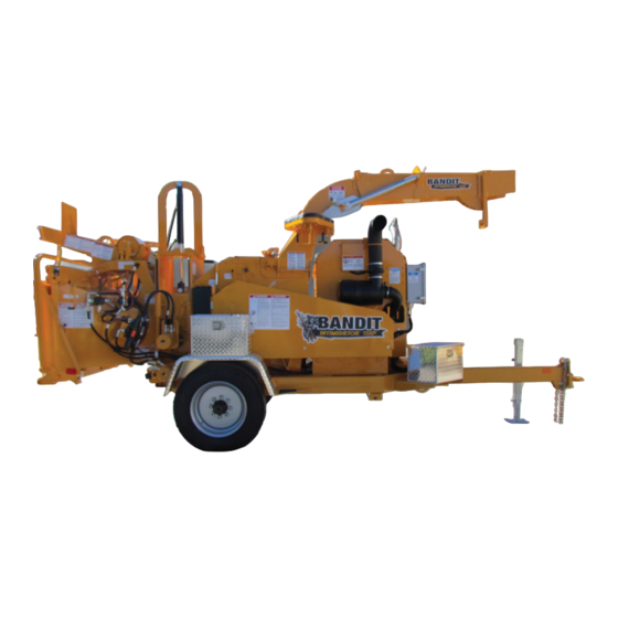
INTIMIDATOR™ 15XP / 1390
INTIMIDATOR 15XP / 1390
Model No: __________________________
Serial No: __________________________
Engine Make: _______________________
Serial No: __________________________
Serial No:
Clutch Make: ________________________
Clutch Make:
Model: ___________ S/N _____________
Model: ___________ S/N
DEALER:
DEALER:
Name: _____________________________
Name:
Address: ___________________________
Address:
City/State: __________________________
City/State:
Phone No: __________________________
Delivery Date: _______________________
Copyright 9/18
ATTENTION:
Depending on what replacement parts you are ordering, we will need the following information:
CHIPPER COMPONENTS
ENGINE COMPONENTS
CLUTCH COMPONENTS
Serial Number
Brand
Brand
Model Number of Chipper
Engine Serial Number
Clutch Serial Number
Engine Model Number
Clutch Model Number
MANUFACTURED BY BANDIT INDUSTRIES, INC
PHONE:
989
561-2270
(
)
PHONE:
800
952-0178 IN USA
(
)
FAX:
989
561-2273 ~ SALES DEPT.
(
)
FAX:
989
561-2962 ~ PARTS/SERVICE
(
)
WEBSITE:
www.banditchippers.com
6750 Millbrook Rd. • Remus, MI 49340 • 1-989-561-2270
Advertisement
Table of Contents

Related Manuals for Bandit INTIMIDATOR 15XP/1390


Summary of Contents for Bandit INTIMIDATOR 15XP/1390
- Page 1 Serial Number Brand Brand Model Number of Chipper Engine Serial Number Clutch Serial Number Engine Model Number Clutch Model Number MANUFACTURED BY BANDIT INDUSTRIES, INC PHONE: 561-2270 PHONE: 952-0178 IN USA FAX: 561-2273 ~ SALES DEPT. FAX: 561-2962 ~ PARTS/SERVICE WEBSITE: www.banditchippers.com...
- Page 2 CALIFORNIA PROPOSITION 65 WARNING ADVERTENCIA Breathing diesel engine Respirar gases de escape de exhaust exposes you to motores diesel expone chemicals known to the quÍmicos conocidos por el estado State of California to cause de California como causales de cancer and birth defects or cáncer y defectos congénitos u other reproductive harm.
- Page 3 ACCIDENTS INVOLVING BRUSH CHIPPERS CAN AND SHOULD BE PREVENTED... Operator training and enforcement of safety policies are ESSENTIAL! Bandit Industries, Inc. Safety Booklet...
- Page 4 If you have purchased a Brush Bandit® Chipper second hand, know someone that has, or have resold a Brush Bandit® Chipper - please contact us. Please fax us at (989) 561-2273 or e-mail us at www. banditchippers.com with the chipper model number, chipper serial number, and current owners name, address, etc.
- Page 5 The following safety features have been developed for, and are currently being used on Brush Bandit® Chippers. They are available from your local Bandit® Dealer. Some are new and some have been presented before. We urge you to update your chippers with these devices.
- Page 6 Also supply the inside width dimension of the inlet end of the infeed hopper or existing 18” deep folding infeed pan. Folding infeed pans were optional on Bandit Chippers for many years. The 18” deep infeed pan became standard equipment on Bandit hand-fed chippers in February 1994.
- Page 7 The chipper hood must NEVER be opened, or pushed closed if the disc/drum is turning. When you supply the chipper model and serial number, this kit is available through your local Bandit® dealer. You also need to supply us with the engine make and model, then we will include the electric schematic to wire the device into the engine system.
- Page 8 Have you heard reports or seen your employees bending over and reaching into the infeed hopper, near the feedwheels? Along with the wooden push paddle and the infeed hopper tray, Bandit Industries, Inc. began installing on their mechanical feed hand fed chippers the patented “Last Chance Stop” cable system. This system has been standard on Bandit®...
- Page 9 FEED CONTROL BAR FEED CONTROL BAR R E V E R Brush Bandit® Chippers that are designed to be hand fed have F E E D a simple, easy to reach feed control bar located across the top and A R D F O R W down both sides of the infeed hopper.
- Page 10 Don’t slam the chipper hood open! It damages the hinge! The hinge needs periodic lubrication to properly operate and to avoid excessive wear! The hinge, hood rest, and hood require scheduled inspection. If they are damaged, replace them! Use only a Bandit factory replacement part.
- Page 11 Insert a small branch into the feedwheel(s). If the chips discharge properly, the chipper is clear and normal operation may resume. Bandit Industries, Inc. Safety Booklet viii...
- Page 12 Striped tape can be obtained through your local Bandit® dealer. The striped tape can be ordered by the foot under part number 900-9901-69.
- Page 13 When the need arises to replace a machine component with a decal attached, be sure and replace the decal. Replacement decals are available, and can be purchased from the manufacturer or your Bandit Dealer. Peel back about half of the backer paper on the decal. Position it on the flat, dry, clean surface so it is smooth and secure.
- Page 14 Training is essential! It is extremely important for everyone who operates a wood chipper to be trained. Operating instructions for the chipper are included in Bandit manuals, decals, and training videos with each chipper sold. We also highly recommend that you use the NAA chipper safety video.
- Page 15 11. _____ The customer has received instruction and fully understands that warranty will not apply if the machine is operated with replacement parts or equipment not manufactured or recommended by Bandit Industries, Inc. 12. _____ The customer has received, been advised, and understands the manuals, and the Safety/Service video supplied with the chipper.
- Page 16 Copyright 2-17 FORM #Q-111 DATE PURCHASE: ______________________ TO BE RETURNED AFTER THIRTY (30) DAYS OF OPERATION MODEL: ________________________________ SERIAL NUMBER: _______________________ Please return to: Customer Data Department 6750 Millbrook Road DEALER NAME: ________________________ Remus, MI 49340 _______________________________________ Phone: (800) 952-0178 in USA Phone: (989) 561-2270 Fax: (989) 561-2273...
-
Page 17: Table Of Contents
FUEL & HYDRAULIC TANK COMPONENTS ....... 126 OPTIONAL COMPONENTS ............128 SERVICE RECORD ................140 BANDIT CONTROLS ................143 NOTICE ANY PART, PORTION, DESIGN, NUMBER, SPECIFICATION, AND/OR DIMENSION IN THIS MANUAL IS SUBJECT TO CHANGE WITHOUT NOTICE BY THE MANUFACTURER. -
Page 18: Introduction & Warranty
NOTICE The producer of this Bandit product reserves the right to make any modifi cations or revisions to the design or specifi cations of its machine without advance notice. The producer also reserves the right to change machine and part prices as needed without advance notice. -
Page 20: Serial Number Locations
WORK ORDER NUMBER LOCATIONS NOTICE 1. S/N on side of frame 2. W/O # on top of tongue The engine information is located on the engine block. The clutch information is located on the clutch plate (if equipped). Bandit Copyright 9/18... -
Page 21: Safety Procedures
Operators must at all times be located within machine. You may obtain additional copies of this easy reach of all feed control and shut‑off devices manual from your Bandit Dealer. when the unit is running. They must be attentive and Before operating machine, you must have all prepared to activate the devices. - Page 22 15 minutes to allow control devises operate properly. They must function, the system to warm up to operating temperature. shift and position smoothly and accurately at all times. Faulty controls can cause personal injury! Bandit Copyright 9/18...
- Page 23 “Daily Start Up & Maintenance”. Make no shields in place and properly secured. modifi cations to your equipment unless specifi cally DANGER recommended or requested by Bandit Industries Inc. DANGER Never feed any materials that might contain wires, stones, nails, metal objects, or any foreign...
- Page 24 RPM to full throttle. Engaging and Block disengaging the clutch at high engine RPM will quickly and excessively wear out clutch plates as well as bearings. Refer to clutch manufacturer’s manual for proper service and operation. Bandit Copyright 9/18...
- Page 25 The ANSI required control bar is designed to reverse the feedwheels when pushed. Check the direction and proper operation of the control bar before operating the chipper. CORRECT OPERATION OF FEED CONTROL BAR PUSH TO FEEDING REVERSE FEEDING FEEDING Bandit Copyright 9/18...
- Page 26 Path Travel DANGER Path Keep hands clear of all pinch points. DANGER Do not touch hot machine surfaces. The machine surfaces may be hot due to the machine operating recently or the machine setting in the sunlight. Bandit Copyright 9/18...
- Page 27 NOTICE resulting in serious injury or death to workers nearby. The Bandit has only been run for a short time to DANGER test proper hydraulic pressures, possible leaks, etc.
- Page 28 SAFETY PROCEDURES FOR OPERATING OPTIONAL HYDRAULIC WINCH This Notice describes important safety information for all Brush Bandit wood chipper owners and operators. The information below is meant to provide you with notice of a potentially dangerous situation that can and should be avoided.
- Page 29 DANGER personal injury! DANGER Make sure everyone is clear of machine before moving the machine. Stay clear of undercarriage DO NOT entangle feet or hands in undercarriage travel system when the machine is moving. travel system. Bandit Copyright 9/18...
-
Page 30: Equipment Specifications
78” (2.0 m) Width: 90” (2.3 m) Weight: Weight: 8000 lbs. (3630kg) 11,000 lbs. (5670kg) Fuel Tank Capacity: 30 gal. (113L) Fuel Tank Capacity: 50 gal. (189L) Hydraulic Tank Capacity: 12 gal. (45L) Hydraulic Tank Capacity: 50 gal. (189L) Bandit Copyright 9/18... -
Page 31: Decals
7. Remove padlock from hood pin. 8. Press down and hold hood spring lock pin (on disc chippers). 9. Retract hood pin. DO NOT RESTART UNTIL ALL GUARDS AND HOODS ARE SECURELY AND PROPERLY INSTALLED. D-03 6/17 Bandit Copyright 9/18... - Page 32 MODEL 15XP/1390 DECALS DECAL LOCATIONS Decal locations may vary, these are general locations. 6,10 2,20 7,9,35 20,24,25 57,62 2,13 41,63,64 3,18,31, 15,42,43, 4,14 52,65 32,59 44,45,66 17,28,29,30, 2,19 31,38,56 11,21 20,24 5,41 2,13,25,58 36,37 8,36,44, 45,47 Bandit Copyright 9/18...
- Page 33 SPD-53 ...Always Use Some Sort Of Mechanical Device... SPD-54 Winch Operation SPD-62 Stay Clear...Tongue Jack SPD-70 Keep Hands Clear... ID-67 Bandit Industries Inc...USA INST-02 Yoke Lock Hole INST-03 Yoke Lock Bar INST-04 Arrow INST-05 Yoke Lift Up / Down INST-07...
- Page 34 MODEL 15XP/1390 DECALS DECAL LOCATIONS Decal locations may vary, these are general locations. 6,10 2,20 7,9,35 20,24,25 57,62 2,13 41,63,64 3,18,31, 15,42,43, 4,14 52,65 32,59 44,45,66 17,28,29,30, 2,19 31,38,56 11,21 20,24 5,41 2,13,25,58 36,37 8,36,44, 45,47 Bandit Copyright 9/18...
- Page 35 Cable Rope Shear Req’D Maintenance SPW-31 Explosion Hazard SPW-40 Hydraulic Winch... 900-8900-32 Basic Safety Decal Kit (Options may require additional decals) 900-8910-74 Bandit Model 15XP Logo Decal Kit 900-8901-45 Bandit Model 1390 Logo Decal Kit 900‑2909‑94 Red Reflective Decal 900‑2909‑95 Amber Reflective Decal 900‑9901‑69...
- Page 36 DECALS DECALS Decals located on your Bandit equipment contain useful information to assist you in operating your equipment safely. Some of the decals on your machine and their location are shown in this section. It is very important that all decals remain in place and in good condition on your machine. Please follow the care and instructions given below.
- Page 37 MODEL 15XP/1390 DECALS Bandit Copyright 9/18...
- Page 38 MODEL 15XP/1390 DECALS Bandit Copyright 9/18...
-
Page 39: Autofeed Options
For part numbers on the hydraulic portion of the autofeed systems refer to pages 116 - 117 of the chipper manual. Refer to the Bandit Controls manual for more information. Do not power wash the digital tach hour meters. Pressure causes unwarranted damage. Do not spray tach, this will void warranty. - Page 40 Pulses per revolution. On magnetic pick-up machines, this setting will be the number of teeth on the gear or sprocket it is reading. On alternator pick-up machines, the setting will need to be obtained from your local dealer or Bandit Industries. Mag Pick-up Magnetic pick-up, also called pick-up probe.
- Page 41 - Replace solenoid and/or cartridge. - System pressure. - Check and readjust per manual specifi cations. - Faulty tach. - Consult local dealer or Bandit Industries. No Signal - Engine not running. - Normal operating condition. - Bad signal wire.
- Page 42 (FOR ALL AUTOFEED SYSTEMS - REFERENCE ONLY) NOTICE Refer to the Completion/Check Sheet, that is shipped with the machine for the correct engine rpm. If needed, contact your local dealer or Bandit Industries. Maximum Feed Reverse Some Current Engine Types Time GM 4.3 - 130 Hp...
- Page 43 To reposition, read the following A. Follow the travel path. steps: B. Feed only from the side of the infeed tray. A. Reverse the feedwheels, reposition C. Release the limb or log. the limb or log, and feed again. D. Turn away and keep moving after releasing B. The log may need to be removed from the the limb or log and from the infeed hopper. machine to a safe work area and trimmed before attempting to feed again if it still will not feed. Bandit Copyright 12/20 INSERT...
- Page 44 SHUT DOWN 1. Stop feeding material. 7. Shut the engine off. 2. Allow the machine to clear out any remaining 8. Remove the key, and make sure it stays in your material. possession. 3. Make sure the top feedwheel is in the lowered 9. Allow the machine to cool down position. 10. Remove all debris, wood chips, sawdust, leaves, 4. Throttle the machine down. etc. from the machine. 5. Disengage the clutch. 11. If transporting the machine, follow the transport 6. Wait for the chipper drum or disc to come to a procedures. complete stop. Bandit Copyright 12/20 INSERT...
- Page 45 MODEL 15XP/1390 CONTROLS MACHINE ORIENTATION REFERENCE D I A D I S S I D I V E S I D I N F Bandit Copyright 9/18...
-
Page 46: Controls
10. Yoke Lift Cylinder “Optional” 11. Swivel Discharge 12. Discharge Chute 13. Discharge Flipper Adjuster 14. Autofeed Controls “Optional” 15. Engine Controls, Adjusters 16. Electric Engine Throttle Adjuster (if equipped) 17. “Bandit” Lever Throttle Adjuster (if equipped) 14,15,16 Bandit Copyright 9/18... - Page 47 The hydraulic tongue jack control handle is in the off position when it is in the center location. Install the lock pin at the desired tongue height. Bandit Copyright 9/18...
- Page 48 FEED CONTROL BAR SHOULD PIVOT WITH LITTLE EFFORT, BY HAND OR WITH A PULL ON “LAST CHANCE” CABLES. LUBRICATE PIVOT POINTS OF FEED CONTROL BAR WEEKLY. ADJUST PIVOT TENSION WITH THE TIGHTNESS OF INSIDE FRICTION NUTS. SECURE ADJUSTMENT WITH OUTSIDE JAM NUTS. Bandit Copyright 9/18...
- Page 49 - Be aware of the hazards of winch line breakage. Ensure that everyone remains clear of the recoil area in the event of load or line breakage. - Pull loads in a manner that avoids angles which could result in tipping or other unintended movement of the chipper and towing vehicle. Bandit Copyright 9/18...
- Page 50 6. Make sure everyone is clear. Use the winch control valve or the radio remote control (if applicable) to now pull the wood material towards the machine. Check that the controls operate in the correct direction. Bandit Copyright 9/18...
- Page 51 5. Make sure everyone is clear and then retract the clutch lock pin and then pull the clutch handle up to engage the winch clutch (see Figure 1). Make sure the handle is locked in position. Bandit Copyright 9/18...
- Page 52 CABLE (TIGHT WHEN ELECTRIC DISABLE PLUG PADLOCK PLUGGED IN AND SOCKET ELECTRIC PADLOCK IS IN!) PADLOCK DISABLE PLUG SOCKET HOOD PIN CHIPPER HOOD HOOD PIN CHAIN HOOD DOOR DRUM CHIPPER DISC CHIPPER Bandit Copyright 9/18...
- Page 53 The sliding air vent can be adjusted by loosening the knob and moving the vent to the open or closed position. There is one on each side of the drum housing. Bandit Copyright 9/18...
- Page 54 - Test the force it takes to activate the Hydraulic Bump Bar with a belt tension gauge or similar type of spring gauge. The force should be approximately 25-30 lbs (11-14 kg). - If everything else checks out, the detent in the bump bar valve may need to be checked, repaired, or replaced. Bandit Copyright 9/18...
- Page 55 If the sliding tongue does not need to be extended for the towing vehicle, depending on hitch type and placement, reverse the procedure above and retract the tongue back to the non extended tongue length. Remove and reinstall these bolts Bandit Copyright 9/18...
- Page 56 To decrease you would push in the knob or turn the handle the opposite way. “Bandit” Lever Lock Cable Throttle System (if equipped): The Bandit throttle system has (2) positions, HIGH and LOW. Engine R.P.M. is controlled by moving the lever from one position to the other.
-
Page 57: Transportation Procedures
25. Do not drive too fast for road conditions or exceed speed regulations for equipment towing. Machine must be hauled level and the towing vehicle must be sized to handle hitch weight, towing weight, and braking requirements. Bandit Copyright 9/18... - Page 58 10. With the engine and the machine at as low a speed as possible, move the machine toward the ramp system. Make sure the alignment is correct throughout the travel. 11. Properly secure the equipment and the area to avoid any possible accidents or dangers. Bandit Copyright 9/18...
- Page 59 MODEL 15XP/1390 MAINTENANCE MACHINE ORIENTATION REFERENCE D I A D I S S I D I V E S I D I N F Bandit Copyright 9/18...
-
Page 60: Maintenance
Failure to properly break-in your engine may result in poor bearing and piston ring surfaces. NOTICE The Bandit has only been run for a short time to test proper hydraulic pressures, possible leaks, etc. The fuel tank will be empty. Fuel is provided through a small auxiliary tank for testing. This immensely helps maintain safety in our manufacturing facility and while shipping. - Page 61 Once they slip you must Improper service, maintenance, or neglect will cause replace them. Check hydraulic pump drive belts also overheating problems and/or engine failure. if equipped. See pages 66 - 67 for procedures. Bandit Copyright 9/18...
- Page 62 33. Review all safety procedures on decals, from per PTO clutch manufacturer’s manual. Bandit manual, and from video. Industries, Inc. does not warranty clutch failures. 34. Make sure all safety equipment is being worn: 26.
- Page 63 5. Check chipper bearings and chipper sheave: 10. Lubricate “Bandit” lever throttle cable: Check, retighten all bearing bolts, bearing lock If the machine is equipped with a “Bandit” lever collars, and also belt sheave bushings to correct throttle system, lubricate inner throttle cable and torques.
- Page 64 33. Review all safety procedures on decals, from manual, and from video. 34. Wear all applicable safety equipment: hard hat, face shield, gloves, eye protection, ear protection, etc. 35. Remember to check EVERYTHING on the checklist. Bandit Copyright 9/18...
- Page 65 Check and grease or oil wheel bearings, follow axle MFG. instructions. Check and adjust brakes, follow axle MFG. instructions. Check and adjust discharge chain tension (if equipped). 10. Lubricate “Bandit” lever throttle cable (if equipped). 3 MONTH CHECK LIST Every three months these checks must be made: OK REPAIRED Replace hydraulic filter(s) after first 10 hours then quarterly or every 400 hours.
- Page 66 8 Lug Hubs (22mm x 1.5 Studs) ......450 - 500 ft.-lbs. Torque (610 - 678 Nm) (Flange Nut) 10 Lug Hubs (3/4” - 16 Studs) ......450 - 500 ft.-lbs. Torque (610 - 678 Nm) (Consult axle manufacturers manual shipped with each machine for specific axle‑stud‑wheel combination lug nut torques.) Bandit Copyright 9/18...
- Page 67 MAINTENANCE PAINT CARE To help keep up the appearance of your Bandit equipment and reduce the possibility of surface rust follow these steps: 1. The machine should be washed on a regular basis with a non-abrasive mild detergent and then rinsed thoroughly.
- Page 68 MAINTENANCE ITEM WHAT TO CHECK RESULTS 1. Sharp knives - Bandit approved 1. Proper sharpening procedures new knives or professionally will pay dividends! Maintaining...
- Page 69 See if they are 10. Autofeed stuck or full of debris warranty. 3. Refer to the autofeed manual for troubleshooting and the owners manual for additional troubleshooting and information on settings. Bandit Copyright 9/18...
- Page 70 Dry lube (swivel discharge, chain 6 Chain Driven Components driven feedwheels, etc.) 7 Pintle Eye Ring Grease to reduce wear 8 Bandit Throttle Cable Lubricate inner cable & ends SAE 10W/30 9 Discharge Swivel Plates 3 Months Grease as needed 10 Clutch Grease per MFG’s instructions...
- Page 71 Use as a reference only, locations may vary depending on options or component manufacturer. NOTICE Lubrication point instructions are described on the machine, in the Lubrication & Coolant Section and Maintenance Section of this manual, or component manufacturer’s manual. Bandit Copyright 9/18...
- Page 72 - in. 16. “Bandit Lever Throttle Cable (if equipped): If the machine is equipped with a “Bandit” lever throttle system, lubricate inner throttle cable and cable ends with a cable lube or SAE 10W/30 oil every month.
- Page 73 .120” (3.0 mm) from Each knife installed in every new machine at Bandit the highest knife. has the Knife Saver used on it before leaving the B.
- Page 74 KNIFE SHARPENING Only Bandit knives and hardware are recommended for use in your Bandit chippers. Only then can you be assured of a quality product that fi ts and performs the best to the standards of excellence that is expected from the Bandit chipper.
- Page 75 KNIFE CHANGING PROCEDURE Only Bandit knives and hardware are recommended for use in your Bandit chippers. Only then can you be assured of a quality product that fi ts and performs the best to the standards of excellence that is expected from the Bandit chipper.
- Page 76 Drum Head Knife Anvil Bolts Anvil Bolts Anvil Clamp Torque To Torque To Plate Specs Specs Anvil Adjuster Anvil Puller Anvil Adjuster Anvil To Anvil Bolt Block Bolt Knife Gauge Bandit Copyright 9/18...
- Page 77 2. In order to check the clearance one person will need to climb into the infeed hopper. Use a feeler gauge or the anvil to knife gauge supplied by Bandit to check the clearance of the first knife to the anvil.
- Page 78 3. Remove the drum lock pin. 4. Use a feeler gauge or the anvil to knife gauge supplied by Bandit to check the clearance of the fi rst knife to the rope/line shear. Check the clearance at the left and right sides of the knife.
- Page 79 6. Apply Loctite 243 (blue) to the adjustment hex bolts and torque them to 180 ft-lbs (244 Nm). 7. Tighten the rope/line shear adjustment covers. 8. Remove the drum lock pin and carefully rotate the chipper drum to make sure all the knives clear the rope/line shear. Bandit Copyright 9/18...
- Page 80 REPLACEMENT PLATE DANGER Do not operate the machine without the chip breaker assembly or the replacement plate bolted to the bottom mount plate and the bottom mount plate bolted to the belly band of the drum housing. Bandit Copyright 9/18...
- Page 81 Insert a small branch into the feedwheel(s). If the chips discharge properly, the chipper is clear and normal operation may resume. Bandit Copyright 9/18...
- Page 82 3. Push or pull down on the belt until the belt has deflected 1/4” (6.4 mm). 4. Record push or pull down force. The force should be 12 lbs (5.4 kg). 5. Adjust the belt tension if the force falls outside of this range. Bandit Copyright 9/18...
- Page 83 150 Hp or above. needed adjustment or replacement. Pump Drive Belts: 1/4” (6.4 mm) deflection GOOD BELT WORN SHEAVE WORN BELT with 12 lbs (5.4 kg) of force. BELT BELT BELT SPACE SHEAVE SHEAVE SHEAVE Bandit Copyright 9/18...
- Page 84 Do not spend excessive time trying to remove the pin and coupler. If problems occur during pin and coupler removal, contact your nearest dealer or Bandit Industries.
- Page 85 2. Loosen the locking screws in several stages by using 1/2 turns, following a clockwise or counter-clockwise direction, until the coupling can be moved on the shaft. 3. Remove the feedwheel motor and then the coupler. Locking Screw Taperlock Keyless Coupler Bandit Copyright 9/18...
- Page 86 Loosen the locknut with an impact spanner wrench or a soft drift pin in a counter-clockwise direction until the bearing adapter assembly becomes completely loose. Remove the mounting bolts. The bearing should slide freely off the shaft. Figure 2 Visual Indicator Over Screw Tightened Locknut Adapter Sleeve Bandit Copyright 9/18...
- Page 87 3 through 13 need to be repeated. 15. Tighten the set screws in the locknut of both bearings to 13-15 ft.-lbs. (18-20 Nm) of torque with a 5/32” hex type torque wrench. Figure 3 Adapter Sleeve Locking Locknut Inner Bore Keyway Bandit Copyright 9/18...
- Page 88 9. Loosen all the bearing bolts to release the preload on the bearings if there is any. Bolt both bearings down and torque the bolts to 220 ft.-lbs. (298 Nm) 10. If the drum head does not spin freely, there is a preload on the bearings and steps 7 through 9 need to be repeated. Bandit Copyright 9/18...
- Page 89 (WITH THE GRIP TIGHT BEARING BEHIND FEEDWHEEL MOTOR) Your Bandit Chipper may be equipped with a tapered lock style (Grip Tight) feedwheel bearing on the hydraulic motor side of the feedwheel and a conventional (set screw) style on the opposite side. With the Grip Tight bearing this gives a very positive locking system to the feedwheel shaft.
- Page 90 If these measurements are not within specifi cations, the bump bar needs to be checked for worn, loose, damaged, or broken parts. Repair or replace parts as needed and/or contact the nearest dealer or Bandit Industries for assistance. Using a belt tension gauge, the bump bar should activate with approximately 25-30 lbs (11-14 kg).
- Page 91 VIEW FROM THE BOTTOM SIDE OF THE TRAY WITH COVERS REMOVED Lubricate the pivots points with a dry lube weekly or as needed. Bandit Copyright 9/18...
- Page 92 With the pin in position 4 the Easy Climb System will have approximately 0” of travel before you start BOTTOM spring tension. Use this position when chipping small YOKE brush type material. BOTTOM MOUNT ADJUST ACCORDINGLY AS SPRINGS STRETCH. Bandit Copyright 9/18...
- Page 93 Automatic Adjusting 12,000 Lbs. 12 1/2” x 5” Elec. or Hyd. .040” (1 mm) Automatic Adjusting For additional brake adjustment procedures consult the axle manufacturer manual. For additional parts break downs and service videos go to www.dexteraxle.com Bandit Copyright 9/18...
-
Page 94: Hydraulics
7. Remove padlock from hood pin. 8. Press down and hold hood spring lock pin (on disc chippers). 9. Retract hood pin. DO NOT RESTART UNTIL ALL GUARDS AND HOODS ARE SECURELY AND PROPERLY INSTALLED. D-03 6/17 Bandit Copyright 9/18... - Page 95 >95 >95 Flash Point >240°C/464°F >200°C/395°F >210°C/410°F >220°C/430°F >220°C/430°F >240°C/464°F Oxidations Stability >9,000 Hours >3,000 Hours >3,000 Hours >3,000 Hours >3,000 Hours >3,000 Hours (ASTM D0943) Cold Start-up, -40°C/-40°F -34°C/-29°F -26°C/-14°F 19°C/-3°F -9°C/16°F -4°C/24°F No Load, Max Bandit Copyright 9/18...
- Page 96 Choose a fl uid that has test results in these areas for best results. Based on the varying temperatures of the area where Bandit equipment is used, and the high demand and loads placed on this equipment, Bandit has fi lled each hydraulic system with Petro‑Canada’s Hydrex XV All Season Hydraulic Fluid for maximum protection and performance.
- Page 97 These typical hydraulic flows and relief pressure settings are with the engine at full RPM. All settings are subject to change! CAUTION After the initial start‑up of the machine and after any replacement of hydraulic components, that fittings and hoses should be re-checked for leaks and clearances. Bandit Copyright 9/18...
- Page 98 MODEL 15XP/1390 HYDRAULICS HYDRAULICS THE BANDIT HYDRAULIC SYSTEM The Bandit is equipped with a very efficient, simple • If the Bandit’s hydraulic system is kept clean and hydraulic system. Each component is capable of the hydraulic pressures are not increased beyond the...
- Page 99 Anything which has been disassembled or tampered with will not be warranted. Items being returned must be clean. All hydraulic components must have all hosing ports plugged. Failure to plug ports will allow debris to enter components which will void warranty. Bandit Copyright 9/18...
- Page 100 MODEL 15XP/1390 HYDRAULICS YOUR BANDIT CHIPPER IS EQUIPPED WITH ONE OF TWO HYDRAULIC PRESSURE ADJUSTMENT PROCEDURE OPTIONS. From Pump To Tank Feedwheel Main Main Relief Control Valve Relief Block GAUGE Flow Divider Main Relief Block Autofeed Motor Block Relief PLUG...
- Page 101 MODEL 15XP/1390 HYDRAULICS YOUR BANDIT CHIPPER IS EQUIPPED WITH ONE OF TWO HYDRAULIC PRESSURE ADJUSTMENT PROCEDURE OPTIONS. GAUGE BALL VALVE From Pump To Tank Main Main Relief Feedwheel Relief Block Control Valve Flow Divider Main Relief Block Autofeed Motor Block...
- Page 102 Turn clockwise using a 1/4” allen wrench to increase pressure, but do not surpass maximum of the specifi ed PSI (bar). Previous valves require 7/32” allen wrench or a fl at head screw driver. HEX HEAD PLUG: Remove to access the relief valve. Bandit Copyright 9/18...
- Page 103 Readjust relief pressure setting if needed, if not needed, shut off engine and remove plug and pressure gauge. Reassemble control valve to optional motor or cylinder. Check for hydraulic leaks. 10. Relief valve pressure should be checked and/or readjusted every month for best performance. MAINTAIN HYDRAULIC PRESSURE AT SPECIFIED PSI (bar). Bandit Copyright 9/18...
- Page 104 Flow control is on for too long Open fl ow control MAINTAIN FEEDWHEEL HYDRAULIC PRESSURE AT SPECIFIED PSI (bar) Follow typical hydraulic flow and relief settings on pages 81 ‑ 87. Follow proper hydraulic oil requirements on pages 79 - 80. Bandit Copyright 9/18...
- Page 105 2. If your machine has Live Hydraulics, see page 92 on how to check a hydraulic motor. 3. If your machine does not have Live Hydraulics, contact your local dealer or Bandit Industries for instructions. NOTICE When returning hydraulic components for warranty make sure to box up all warranted parts to avoid additional damage while shipping.
- Page 106 Flow Control Gauge Valve removing First hose. component after pump. Flow Direction In-Line Fitting Relief Outlet Hose supplied by you. Pump Do not exceed 90% of system pressure. Remove any fi ller neck screen. Hydraulic Flow Tank Direction Bandit Copyright 9/18...
- Page 107 12. If 90% of the main relief pressure can not be obtained and/or the fl ow rate passing through the meter is considerably less, then the pump is worn or damaged. Flow Meter (with relief) Hose supplied by First you. component after pump. Flow Direction Outlet Do not exceed Pump 90% of system pressure. Flow Hydraulic Direction Tank Bandit Copyright 9/18...
- Page 108 5 gallon (19L) pail. The following instructions are for machines with Live Hydraulics, for machines without Live Hydraulics contact your local dealer or Bandit Industries. In order to check out a hydraulic motor, it is necessary to mechanically stop the motor from turning while under load.
- Page 109 Shift valve with hand lever to assure operation. With some eff ort, the hand lever should move between three positions. The detent will hold the hand lever in the three positions. Instructions and illustrations provided by component manufacturer. Bandit Copyright 9/18...
-
Page 110: Electrical
6 Wire Main Cable Color Code LEFT TURN-YELLOW WIRE Black BL (Brakes) White W (Ground) ELECTRIC BRAKES-BLACK WIRE Green G (Right Turn) Yellow Y (Left Turn) GROUND-WHITE WIRE Brown BR (Running Lights) Red R (Breakaway Switch) RUNNING LIGHTS-BROWN WIRE Bandit Copyright 9/18... -
Page 111: Replacement Parts
Some of the components shown in this section are for optional equipment and may not apply to every machine. NOTICE Bandit Industries Inc. reserves the right to make changes in models, size, design, installations and applications on any part without notification. - Page 112 MODEL 15XP/1390 INFEED HOPPER COMPONENTS MODEL 1390 TAIL LIGHT ASSEMBLY (PRE 4/16) NOTICE Parts may not be exactly as shown. Bandit Copyright 9/18...
-
Page 113: Infeed Hopper Components
NOTICE The Model 1390 hydraulic feedwheel motors may be on the left side or the right side of the machine, depending on the machine serial number. NOTICE Grip-Tite style feedwheel bearings are on the hydraulic motor side. Bandit Copyright 9/18... - Page 114 MODEL 15XP/1390 INFEED HOPPER COMPONENTS MODEL 1390 TAIL LIGHT ASSEMBLY (PRE 4/16) NOTICE Parts may not be exactly as shown. Bandit Copyright 9/18...
- Page 115 NOTICE The Model 1390 hydraulic feedwheel motors may be on the left side or the right side of the machine, depending on the machine serial number. NOTICE Grip-Tight style feedwheel bearings are on the hydraulic motor side. Bandit Copyright 9/18...
- Page 116 MODEL 15XP/1390 INFEED HOPPER COMPONENTS MODEL 1390 TAIL LIGHT ASSEMBLY (PRE 4/16) NOTICE Parts may not be exactly as shown. Bandit Copyright 9/18...
- Page 117 NOTICE The Model 1390 hydraulic feedwheel motors may be on the left side or the right side of the machine, depending on the machine serial number. NOTICE Grip-Tite style feedwheel bearings are on the hydraulic motor side. Bandit Copyright 9/18...
- Page 118 MODEL 15XP/1390 CHIPPER COMPONENTS NOTICE Parts may not be exactly as shown. Bandit Copyright 9/18...
-
Page 119: Chipper Components
Discharge Spring Lock 900-7900-96 Rubber Cap (Not Shown) 909-3000-48 Optional Clean-Out Door ** Components vary with engine options order by physical description or machine S/N. NOTICE Nuts, bolts, washers, and all other components can be ordered by physical description. Bandit Copyright 9/18... - Page 120 MODEL 15XP/1390 CHIPPER COMPONENTS NOTICE Parts may not be exactly as shown. Bandit Copyright 9/18...
- Page 121 Manual Holder - 10” x 12-1/2” x 2” (Stored In Tool Box) ** Components vary with engine options order by physical description or machine S/N. NOTICE Nuts, bolts, washers, and all other components can be ordered by physical description. Bandit Copyright 9/18...
-
Page 122: Chipper Knife & Hardware
Knife Bolt Torque: 180 ft.-lbs. (245 Nm) KNIFE SAVER KIT LOCATION PART NUMBER DESCRIPTION 900-9901-68 Knife Saver Kit 900-9901-65 File For Knife Saver Kit Only 900-9901-63 Replacement Blades For Knife Saver 900-9901-66 Knife Changing Gloves NOTICE Parts may not be exactly as shown. Bandit Copyright 9/18... -
Page 123: Anvil Hardware
Anvil Gauge 904-0003-90 Anvil Hardware Kit Only (Includes 3 - 8) 909-1000-11 Anvil & Hardware Kit (Includes 1a & 3 - 8) Anvil Bolt Torque: 75 ft.-lbs. (102 Nm) NOTICE Parts may not be exactly as shown. Bandit Copyright 9/18... -
Page 124: Discharge Components
MODEL 15XP/1390 DISCHARGE COMPONENTS HEIGHT ADJUSTABLE HAND CRANK & HYDRAULIC SWIVEL DISCHARGE HYDRAULIC SWIVEL HYDRAULIC SWIVEL MOTOR & MOUNT (PRE 6/16) MOTOR & MOUNT NOTICE Parts may not be exactly as shown. Bandit Copyright 9/18... - Page 125 Hydraulic Motor for Swivel Discharge - SAE O-Ring Fitting 900-3973-28 Hydraulic Motor for Swivel Discharge - Pipe Fitting 980-0110-66 Motor Mount for Swivel Discharge 937-1005-35 Chain Guard Mount 937-200061 Chain Guard NOTICE Nuts, bolts, washers, and all other components can be ordered by physical description. Bandit Copyright 9/18...
- Page 126 Hand Crank Swivel And Adjustable Height Discharge Assembly 911-2000-94 Hand Crank Swivel Discharge Assembly 911-2001-27 Adjustable Height Discharge Assembly 911-2000-96 Hydraulic Swivel Discharge Assembly 911-2000-97 Hydraulic Swivel And Adjustable Height Discharge Assembly NOTICE Parts may not be exactly as shown. Bandit Copyright 9/18...
- Page 127 Cylinder Lug Pin - 3/4” Dia. x 2 1/2” & Cotter Pin - 1/4” x 1 1/2” 900-3928-16 Hydraulic Flipper Cylinder 900-3916-62 Swivel Discharge & Discharge Flipper Control Valve (Not Shown) NOTICE Nuts, bolts, washers, and all other components can be ordered by physical description. NOTICE Parts may not be exactly as shown. Bandit Copyright 9/18...
-
Page 128: Hydraulic Components
Quick Coupler 900-3902-23 Test Nipple 900-3911-47 Rubber Cap For Test Nipple 900-3924-86 Fitting 900-3926-11 Ball Valve 900-3922-14 Fitting 980-100121 In-Line Pressure Check Kit - With Autofeed (Includes 1-7) 500-0000-43 Gauge & Quick Coupler Only (Includes 1 & 2) Bandit Copyright 9/18... - Page 129 ** Hydraulic pumps need to be ordered by physical description and serial number of machine. NOTICE The Model 1390STD was built until 8/13. NOTICE Make sure to order components according to fi tting type, fi ttings may vary on all components. NOTICE Parts may not be exactly as shown. Bandit Copyright 9/18...
- Page 130 MODEL 15XP/1390 HYDRAULIC COMPONENTS HYDRAULIC DIAGRAM (WITH OPTIONS) INLET INLET INLET INLET INLET INLET INSERT - HYDRAULIC FLIPPER INLET JIC / SAE PIPE O-RING FITTING INLET Examples of straight fittings. NOTICE Parts may not be exactly as shown. Bandit Copyright 9/18...
- Page 131 ** Hydraulic pumps need to be ordered by physical description and serial number of machine. NOTICE The Model 1390STD was built until 8/13. NOTICE Make sure to order components according to fitting type, fittings may vary on all components. NOTICE Parts may not be exactly as shown. Bandit Copyright 9/18...
- Page 132 900-3923-43 Autofeed Cartridge Only 900-3923-44 12 Volt Autofeed Solenoid Only 900-3919-96 Main Relief Only (Danfoss) 5. a. 900-3923-45 Autofeed Block Assembly With Relief 900-3923-37 Autofeed Block Assembly Without Relief NOTICE Parts may not be exactly as shown. Bandit Copyright 9/18...
- Page 133 7. a. 900-3925-89 10’ Cord and Molded Herschman Connector (Not Shown) 900-3920-71 16’ Cord and Molded Herschman Connector (Not Shown) 900-3918-63 25’ Cord and Molded Herschman Connector (Not Shown) NOTICE Parts may not be exactly as shown. Bandit Copyright 9/18...
- Page 134 MODEL 15XP/1390 HYDRAULIC COMPONENTS HOSE CLAMP HOSE GUARD FLOW DIVIDER NOTICE Parts may not be exactly as shown. Bandit Copyright 9/18...
- Page 135 DESCRIPTION 1. a. 900-3934-76 Hose Guard - 4” Long 900-3934-77 Hose Guard - 6” Long 900-3934-78 Hose Guard - 8” Long FLOW DIVIDER LOCATION PART NUMBER DESCRIPTION 900-3977-41 Flow Divider Body Only 900-3934-30 Flow Divider Cartridge Only Bandit Copyright 9/18...
- Page 136 MODEL 15XP/1390 HYDRAULIC COMPONENTS TYPICAL SPRING LOADED CONTROL VALVE TYPICAL FEEDWHEEL CONTROL VALVES 4,12 1,12 3,12 NOTICE Parts may not be exactly as shown. Bandit Copyright 9/18...
- Page 137 NOTE: INCLUDES #’s 1, 3, & 4 CONTROL VALVES LOCATION PART NUMBER DESCRIPTION 900-3927-73 Yoke Lift Control Valve for Dual Control Yoke Lift 900-3920-01 Winch, Hyd. Swivel Discharge, and Tongue Jack 900-3920-06A Feedwheel Control Valve With Relief 900-3920-05A Feedwheel Control Valve Without Relief Bandit Copyright 9/18...
- Page 138 MODEL 15XP/1390 FRAME & ACCESSORY COMPONENTS OPTIONAL SLIDING TONGUE NOTICE Parts may not be exactly as shown. Bandit Copyright 9/18...
-
Page 139: Frame & Accessory Components
(Grease Type, Oil Type, Never Lube Type). *-* Engine Rails and Adjusters Will Vary Depending on Engine and Component Options. Order By Serial Number of Chipper or Physical Description. NOTICE Other fenders and fender stone shields are optional. Bandit Copyright 9/18... - Page 140 MODEL 15XP/1390 FRAME & ACCESSORY COMPONENTS OPTIONAL SLIDING TONGUE NOTICE Parts may not be exactly as shown. Bandit Copyright 9/18...
- Page 141 (Grease Type, Oil Type, Never Lube Type). *-* Engine Rails And Adjusters Will Vary Depending On Engine And Component Options. Order By Serial Number Of Chipper Or Physical Description. NOTICE Other fenders and fender stone shields are optional. Bandit Copyright 9/18...
- Page 142 MODEL 15XP/1390 FUEL & HYDRAULIC TANK COMPONENTS OPTIONAL HEAVY DUTY LOCKABLE FILLER CAP NOTICE Parts may not be exactly as shown. Bandit Copyright 9/18...
-
Page 143: Fuel & Hydraulic Tank Components
Optional Fill Cap Lock Assembly For Steel Tank With 900-3917-71 Fill Cap NOTICE Components vary with fuel type. Specify gas or diesel when ordering fuel tank components. NOTICE Tank assemblies vary with options. Specify all options when ordering. Bandit Copyright 9/18... -
Page 144: Optional Components
MODEL 15XP/1390 OPTIONAL COMPONENTS DINAMIC WINCH Old Style Docking Bar (Pre S/N 505611) 30 29 30 29 Lock Disengagement Handle NOTICE Parts may not be exactly as shown. Bandit Copyright 9/18... - Page 145 Lock Disengagement Clevis 900-4906-32 1/4”-20NC Nut 980-2004-48 Winch Line Docking Bar 980-2004-47 Winch Switch Frame 35. a. 980-2004-51 Bearing Block 900-4900-06 Grease Zerk NOTICE Nuts, bolts, washers, and all other components can be ordered by physical description. Bandit Copyright 9/18...
- Page 146 MODEL 15XP/1390 OPTIONAL COMPONENTS RKI WINCH NOTICE Parts may not be exactly as shown. Bandit Copyright 9/18...
- Page 147 1/4” Replacement Stud For Selector Valve (900-3920-58 & 900-3913-41) 904-0002-60 Winch Kit - Specify Fairlead or Rollers (Includes 1 - 18, 23 - 29) NOTICE Nuts, bolts, washers, and all other components can be ordered by physical description. Bandit Copyright 9/18...
- Page 148 Vinyl Grip - Black 900-7901-41 Vinyl Grip - Yellow 900-3914-02 Control Bar Pivot Bracket 900-4907-43 Cables 955-300054 Linkage NOTICE Nuts, bolts, washers, and all other components can be ordered by physical description. NOTICE Parts may not be exactly as shown. Bandit Copyright 9/18...
- Page 149 ** Hydraulic pumps need to be ordered by physical description and serial number of machine. NOTICE Make sure to order components according to fitting type, fittings may vary on all components. NOTICE Parts may not be exactly as shown. Bandit Copyright 9/18...
- Page 150 Outside Tube Assembly 900-4907-60 Cotter Hair Pin 914-1000-38 Lock Pin 980-0131-50 Inside Tube Assembly 980-0509-53 Drop Leg Foot Pad Assembly 980-0509-00 Bolt-On Hydraulic Tongue Jack Kit (Includes #’s 1 - 9) NOTICE Parts may not be exactly as shown. Bandit Copyright 9/18...
- Page 151 Pivoting Tongue Cylinder 5. a. 900-3920-01 Pivoting Tongue Valve (SAE O-Rings) 900-3901-42 Pivoting Tongue Valve (Pipe Fittings) NOTICE Nuts, bolts, washers, and all other components can be ordered by physical description. NOTICE Parts may not be exactly as shown. Bandit Copyright 9/18...
- Page 152 MODEL 15XP/1390 OPTIONAL COMPONENTS HYDRAULIC BUMP BAR Version 2 NOTICE Parts may not be exactly as shown. Bandit Copyright 9/18...
- Page 153 900-4917-76 Left Spring for Spring Assist 900-4917-77 Right Spring for Spring Assist 905-3002-14 Push Plate for Momentary Override Switch 900-3956-26 Momentary Override Valve 14. a. 900-2903-07 Momentary Override Push Button Switch 999-8001-88 Momentary Override Timer (Not Shown) Bandit Copyright 9/18...
- Page 154 MODEL 15XP/1390 OPTIONAL COMPONENTS HYDRAULIC BUMP BAR NOTICE Parts may not be exactly as shown. Bandit Copyright 9/18...
- Page 155 900-3956-74 Bump Bar Valve (Not Shown) 13. a. 900-3956-26 Momentary Override Valve (Not Shown) 905-3002-14 Push Plate for Momentary Override Switch (Not Shown) 900-2903-07 Momentary Override Push Button Switch (Not Shown) 999-8001-88 Momentary Override Timer (Not Shown) Bandit Copyright 9/18...
-
Page 156: Service Record
MODEL 15XP/1390 SERVICE RECORD SERVICE RECORD DATE DESCRIPTION AMOUNT Bandit Copyright 9/18... -
Page 157: Bandit Controls
BANDIT CONTROLS HAND FED BANDIT CONTROLS (FUEL SAVER) (RADIO) (WINCH w/ FEED ASSIST) (DUMP VALVE) (BUMP BAR) 245774458290 21Dec2016... - Page 158 BANDIT CONTROLS Main Page To Start, turn key to ON position. In cold weather the engine may pre heat glow plugs or heater grid and the WAIT TO START symbol will appear on the splash screen. When pre heat is complete the Display will continue to Main Page.
- Page 159 BANDIT CONTROLS Main Page Blinking indicates that the system has E-Stopped the engine. - Hood Pin removed - E-Stop depressed (if equipped) Fuel Save Status: indicates that Fuel Save mode is selected, and if “Save” is blinking the system is idled down to save fuel.
- Page 160 BANDIT CONTROLS Mode Page 4. Press the “Bypass” button to manually run Feed Fwd at low Eng RPM and bypass the AutoFeed control. This will allow auxiliary functions to be operated on certain machines equipped with dump valve hydraulics. To turn AutoFeed back on, press the same “Bypass”...
- Page 161 BANDIT CONTROLS Main Page Press the Maint button to navigate to the Maintenance Pages. (Software Serial Numbers) Function Status Error Counts MAINT1 INPUTS Shows the status of communication between devices and various inputs to Controller1 (C1). 1=Good/Active 0=Bad/Inactive The number behind many of the device status is an error count. Each time communication is lost or the status is bad this number will count up to a maximum of 15 until keyswitch is cycled and that memory is cleared.
- Page 162 BANDIT CONTROLS Maint Pages Press the Maint4 button to navigate to Maintenance 4. MAINT2 OUTPUTS Shows the status of Controller1 (C1) outputs that are able to be diagnosed. Observe the note on the screen that output wiring can only be diagnosed for open/broken connection while the output is de-engergized.
- Page 163 BANDIT CONTROLS Maint Pages Input values change from 0 to 1 when that Radio function is active. Error counts for how many times the controller has lost comm with the receiver or transmitter. MAINT4 RADIO The radio and tether systems (optional on some machines) send all of their signals via CAN messages and therefore cannot be checked physically at the receivers with a voltmeter.
- Page 164 BANDIT CONTROLS Notes The tether is a back-up tool in case the radio fails. The tether has 2 (8) button keypads that communicate with the main controller via CAN messages. The machine must be in Tether mode in order to activate the Tether.
- Page 165 BANDIT CONTROLS Setup Page FuelSave Time: this is the amount of time the machine will wait at "no load" until it idles down. Fan Reverse Interval is optional on some machines. It is the time between fan reversing cycles to purge debris from the radiator.
- Page 166 BANDIT CONTROLS Setup Page (Password protected) Fuel Saver - Behind the FuelSave Load setting (42% as shown) is the actual Load on the engine (25% as shown). The setting is typically 5-10% higher than actual load at high idle with clutch engaged.
- Page 167 BANDIT CONTROLS Setup Page FuelSaver If Fuel Saver Mode is turned on, the machine will throttle down on its own to 200 RPM above low idle if it runs too long with no load. Two settings affect Fuel Saver mode.
- Page 168 BANDIT CONTROLS Push Button Feed Assist Stow Switch, Feed Assist Switch Push Button Feed Assist Valve and Switch Manual Winch with Push Button Feed Assist There is a switch on the winch that sends a 12V signal to enable the winch valve. The winch stow switch indicates to the control system whether the winch is stowed or deployed.
- Page 169 BANDIT CONTROLS Electric Feed Assist Winch In-Out Switches, Stow Switch, Feed Assist Switch Electric Winch with Feed Assist There is a switch on the winch that sends a 12V signal to enable the winch valve. The winch switch indicates to the control system whether the winch is stowed or deployed. The status of this switch is displayed on Maint1 as shown above right.
- Page 170 BANDIT CONTROLS Main Page Press this button for the popup menu (Popup menu disappears after 5sec). Popup Menu Options: 1. Press this button for Display Menu. 2. Press for DPF Options (If equipped with relevant T4 engine). 3. Press to view System Faults.
- Page 171 BANDIT CONTROLS Display Menu 1. Select down to the parameter you wish to adjust. 3. & 4. Increase or decrease the value of the selected parameter, or select through various options. 5. Go back. (Engine ECU address is default 0).
- Page 172 BANDIT CONTROLS DPF Options Press to display REGEN options "N/A" will appear if the engine does not have these T4 features. (Main Page will show DPF icons as well) (DPF options are only applicable on T4 engine). 1. & 2. Select the parameter you wish to adjust.
- Page 173 BANDIT CONTROLS Faults and Diagnostic Messages Press to display Faults and error messages. 1. & 2. Select the parameter you wish to select. 3. Enter OK to view those faults. If there are no active or stored faults, none will be available to scroll through.
- Page 174 BANDIT CONTROLS Faults and Diagnostic Messages The Amber LED corresponds to a Diagnostic Warning Condition. The Red LED corresponds to a Diagnostic Stop Condition (ie. stop engine). 245774458290 21Dec2016...
- Page 175 BANDIT CONTROLS Service Reminders Press to display Engine Service page. 1. Select down to the parameter you wish to adjust. 3. & 4. Increase or decrease the value of the selected parameter, or select through various options. 5. Go back.
- Page 176 BANDIT CONTROLS Other Engine Parameters Press to display other engine parameters. The engine may send information on other parameters it is monitoring. These can be read on 1 of 4 engine pages. Cycle through the engine pages to return to the Main Page.
- Page 177 BANDIT CONTROLS Engine Service Tools Main Controller VBBs Fuse When connecting a laptop to the engine with certain engine service tools (ex CAT-ET, etc) it may be necessary to disconnect the main Controller by unplugging the 3amp VBBs fuse in station 3. The engine can still Key ON, start, and idle with the main Controller OFF.
- Page 178 BANDIT CONTROLS Bump Bar Option If the Chipper is equipped with a Bump Bar and Bump Bar Bypass valve, a Bypass Button is connected to the valve which together allow Feed Fwd for 5 seconds even if the Bump Bar has disabled the feed system.
- Page 179 BANDIT CONTROLS Program Notes Display - If Controller 1 (C1) loses communication with the Display, C1 will default to Radio mode. - If C1 loses comm with the Display AND the radio receiver, it will default to Tether Mode. - If C1 loses comm with display and receiver and tether, it will remain in Manual mode internally.
- Page 180 BANDIT CONTROLS Inputs - BadCount01: Hood Pin - BadCount02: EStop - BadCount04: TetherEStop (counts only while in TetherMode) - The buttons on the infeed are tied into Throttle Up when FuelSave is turned on. - Winch In-Out Sw R to Gnd; Open=60,000; In 0Ω=0; Out 1000Ω=AtoD=12,300; compare LT 20,000 FuelSaver - FuelSave Time has a range of 10-255sec.
- Page 181 BANDIT CONTROLS Document notes 21Dec2016 – First Draft 245774458290 21Dec2016...
Need help?
Do you have a question about the INTIMIDATOR 15XP/1390 and is the answer not in the manual?
Questions and answers
What is the diameter and length for the winch line? VIN - 4FMUS1812PR528943 MAKE/MODEL Bandit/Intimidator 15XP