Table of Contents
Advertisement
BRUSH BANDIT
BUILT WITH QUALITY AND DESIGN FIRST
ATTENTION:
Depending on what replacement
parts you are ordering, we will
need the following information:
CHIPPER COMPONENTS
Serial Number
Model Number of Chipper
ENGINE COMPONENTS
Engine Size
Engine Serial Number
Engine Spec. Number
CLUTCH COMPONENTS
Name of Manufacturer
Serial Number
Assembly of Clutch
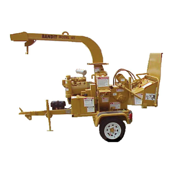
BRUSH CHIPPER
MODEL 65 & 65 CHIPBOX
OPERATING & PARTS MANUAL
Model No: _________________
Serial No: _________________
DEALER:
Name: ____________________
Address: __________________
City/State: _________________
Phone No: _________________
Delivery Date: ______________
Engine Make: ______________
Serial No: _________________
Clutch Make: _______________
Model: _________ S/N _______
PRINTED 5/01
BANDIT INDUSTRIES, INC.
PHONE: (989) 561-2270 OR 561-2272
FAX: (989) 561-2273 ~ SALES DEPT.
FAX: (989) 561-2962 ~ PARTS/SERVICE
65
MANUFACTURED BY
6750 Millbrook Road
REMUS, MICHIGAN 49340
®
Advertisement
Table of Contents

Subscribe to Our Youtube Channel
Related Manuals for Bandit BRUSH BANDIT 65


Summary of Contents for Bandit BRUSH BANDIT 65
- Page 1 Engine Make: ______________ Serial No: _________________ Clutch Make: _______________ Model: _________ S/N _______ PRINTED 5/01 MANUFACTURED BY BANDIT INDUSTRIES, INC. 6750 Millbrook Road REMUS, MICHIGAN 49340 PHONE: (989) 561-2270 OR 561-2272 FAX: (989) 561-2273 ~ SALES DEPT. FAX: (989) 561-2962 ~ PARTS/SERVICE...
- Page 15 5-01 FORM #WV-110 IT IS VERY IMPORTANT THAT THIS FORM IS FILLED OUT COMPLETELY & ACCURATELY. IF WE CANNOT READ THE PURCHASER’S INFORMATION OR IT IS INCORRECT, OUR CUSTOMER LIST WILL NOT BE ACCURATE. IMPORTANT - THIS FORM MUST BE RETURNED TO THE Customer Data Department 6750 Millbrook Road CUSTOMER DATA DEPARTMENT WITHIN TEN (10)
- Page 17 5-01 FORM #Q-104 DATE PURCHASED: _________________ TO BE RETURNED AFTER THIRTY (30) DAYS OF OPERATION MODEL: ___________________________ Please return to: Customer Data Department SERIAL NUMBER: ___________________ 6750 Millbrook Road DEALER NAME: _____________________ Remus, MI 49340 ____________________________________ PH: (989) 561-2270 FAX (989) 561-2273 CHIPPER QUALITY REPORT All of the employees that build your equipment strive to manufacturer the very best quality product on the market.
-
Page 19: Table Of Contents
FRAME & ACCESSORY COMPONENTS ......58 PTO CHIPPER COMPONENTS .......... 62 FEEDWHEEL COUPLER SECTION ........64 NOTE- ANY PART, PORTION, DESIGN, NUMBER, SPECIFICATION, AND/OR DIMENSION IN THIS MANUAL IS SUBJECT TO CHANGE WITHOUT NOTICE BY THE MANUFACTURER. Bandit PRINTED 5/01 PAGE 1... -
Page 20: Introduction & Warranty
The purpose of this manual is to provide the user with specifications and procedures for the operation, maintenance and repair of the BANDIT CHIPPER. As with any piece of equipment, safety should always be a constant thought while the machine is being operated, serviced or stored. In... - Page 22 MODEL 65 MODEL 65 CHIPBOX SERVICE RECORD SERVICE RECORD DATE DESCRIPTION AMOUNT Bandit PRINTED 5/01 PAGE 6...
-
Page 23: Safety Procedures
DANGER! machine. You may obtain additional copies of this manual from your Bandit Dealer. Do not work inside the mouth of the chipper or Before operating chipper, you must have all around the feedwheels, until you have installed the potential operators;... - Page 24 You should always keep a fully charged fire Always block the tires and the machine tongue extinguisher with you while chipping and servicing the whenever the Bandit is unhooked for operation. DO machine. NOT rely on the tongue jack for operational stabilization.
- Page 25 A clutch can self-engage if either the pilot or throw-out bearing happens to seize Most of the nuts used on the Bandit Chipper are to the main output shaft. self locking. After the nut has been removed five...
- Page 26 Operators must at all times be located within easy transporting chipper. Striped tape can be obtained reach of all feed control and shut-off devices when through your local Bandit Dealer. the unit is running. WARNING! WARNING!
-
Page 27: Safety Decals
It is owner’s and operator’s responsibility to use and keep a “Wooden Push Paddle” with chipper, also to secure it when transporting chipper. DO NOT operate this machine unless you have read the operator’s manual and have been trained for safe operating procedures! Bandit PRINTED 5/01 PAGE 11... - Page 28 ALTHOUGH LOCATIONS MAY VARY, ALL DECALS MUST BE ON MACHINE DURING OPERATION IF ANY DECALS BECOME DAMAGED, REPLACE IMMEDIATELY. 7,20, 3,6,39, 27,48 51,62 11,28, 40,60 15,30 9,12, 17,53 19,52 8,42 16,31, 32,38 15,25,49,54, 34,45 57,61,63 4,10, 14,15,30 13,33 41,56 22,26,29 35,36 Bandit PRINTED 5/01 PAGE 12...
- Page 29 NUMBER DESCRIPTION OBW-108 Brush Bandit® OOB-112 Bandit Industries, Inc..OOB-139 Model 65 Optional OOB-155 Property Of Bandit Industries..OOB-213 Do Not Attempt To Operate..OOB-220 Yoke Lock Hole OOB-221 Yoke Lock Bar OOB-223 3 1/4” Arrow OOB-227 Notice Hydraulic Trouble Shooting..
- Page 30 ALTHOUGH LOCATIONS MAY VARY, ALL DECALS MUST BE ON MACHINE DURING OPERATION IF ANY DECALS BECOME DAMAGED, REPLACE IMMEDIATELY. 4,25 30,39, 48,59 47,55, 8,18,37 1,2, 6,7, 1,2,41 15,58 31,34,49,51,57,61 20,25,27 10,28,29,38 54,58,63 8,13,37 1,5,13, 11,21, 19,24 22,43 Bandit PRINTED 5/01 PAGE 14...
- Page 31 Danger! Through This..61. (For 1/2” x 3” x 7 1/4” Knives) OBR-4009 Warning! This Chipper Disc... OBR-4010 Danger! Never, Sit, Stand..OBR-4028 Danger! Do Not Feed..Bandit Model 65 Vinyl Optional California Proposition 65..Optional Spanish/English Decals..Optional Portuguese Decals..
- Page 32 SAFETY DECALS SAFETY DECALS Safety Decals located on your Bandit Chipper contain useful information to assist you in operating your equipment safely. Some of the decals on your machine and their location are shown in this section. It is very important that all decals remain in place and in good condition on your machine. Please follow the care and instructions given below: 1) You should use soap and water to keep your decals clean.
-
Page 33: Equipment Options
An occasional large diameter can be chipped if the hydraulic feed wheels are stopped immediately when the engine begins to lug down. Do not chip continuous large diameter material. Excessive engine overwork will overheat the engine and cause engine failure. Bandit PRINTED 5/01 PAGE 17... - Page 34 MODEL 65 MODEL 65 CHIPBOX EQUIPMENT OPTIONS EQUIPMENT OPTIONS Digital E-287 Autofeed Bandit Part Number 900-2903-56 Bandit PRINTED 5/01 PAGE 18...
- Page 35 MODEL 65 MODEL 65 CHIPBOX EQUIPMENT OPTIONS Digital E-287 Autofeed Bandit Part Number 900-2903-56 Digital E-287 with hour meter and RPM display Features of the E-287 - Speed Switch, Hour Meter, and Tachometer all in one package. - Push-button programmability (no computer connection required).
- Page 36 MODEL 65 MODEL 65 CHIPBOX EQUIPMENT OPTIONS Digital E-287 Autofeed Bandit Part Number 900-2903-56 Operating Instructions Normal Operating Mode During normal operating mode, the user may view the Hours, RPMs, or Total Hours. To view any of these displays, simply press the corresponding button.
- Page 37 MODEL 65 MODEL 65 CHIPBOX EQUIPMENT OPTIONS Digital E-287 Autofeed Bandit Part Number 900-2903-56 Programing The E-287 1) Press and hold SET button while turning key on. Unit briefly displays the letters “PPR” (Pulses Per Revolution) followed by a number indicating the current PPR value.
- Page 38 MODEL 65 MODEL 65 CHIPBOX EQUIPMENT OPTIONS Digital E-287 Autofeed Bandit Part Number 900-2903-56 TROUBLE SHOOTING GUIDE IF THE POWER TO CHECK THE FEED SOLENOID IS INCONSISTENT OR DOES NOT WORK, CHECK THE FOLLOWING WITH A MULTIMETER: MULTIMETER SET AT RX100 RANGE...
- Page 39 MODEL 65 MODEL 65 CHIPBOX EQUIPMENT OPTIONS Digital E-287 Autofeed Bandit Part Number 900-2903-56 TROUBLE SHOOTING GUIDE POSSIBLE CAUSES WHY AUTOFEED DOES NOT WORK OR IS INTERMITTENT: 1. Switch is not turned on. 2. Engine not coming back to full rated RPM.
-
Page 40: Controls
NORMAL WEAR REQUIRES PERIODICAL ADJUSTMENT OF PIVOT TENSION. FEED CONTROL HANDLE SHOULD PIVOT WITH LITTLE EFFORT, BY HAND OR WITH A PULL ON “LAST CHANCE” CABLES. ADJUST PIVOT TENSION WITH THE TIGHTNESS OF INSIDE FRICTION NUTS. SECURE ADJUSTMENT WITH OUTSIDE JAM NUTS. Bandit PRINTED 5/01 PAGE 24... - Page 41 Motor Coupler 4. Swivel Discharge Optional Autofeed Control 5. Feedwheel Control Bar All Bolts & Nuts 6. Engine Throttle Adjuster Lug Nuts 7. Hydraulic Control Valves Knives & Hardware 8. Wooden Push Paddle (Not Shown) Bandit PRINTED 5/01 PAGE 25...
- Page 42 3. Hydraulic Control Valves Motor Coupler 4. Swivel Discharge Optional Autofeed Control 5. Feedwheel Control Bar All Bolts & Nuts 6. Engine Throttle Adjuster Lug Nuts 7. Wooden Push Paddle (Not Shown) Knives & Hardware Bandit PRINTED 5/01 PAGE 26...
- Page 43 This light will glow when the engine, or engine coolant, is above normal operating temperature. If this occurs allow the engine temperature to cool down. If the engine is overheating because of a loss of coolant, or a broken fan belt, shut the engine off immediately. Bandit PRINTED 5/01 PAGE 27...
-
Page 44: Start-Up Procedures
PTO manufacturers manual recommendations. Block tires and tongue for stability. Maintain and service the “Last Chance Stop” system so it is always operational if needed. Remember to check EVERYTHING on the checklist . Bandit PRINTED 5/01 PAGE 28... - Page 45 Failure to properly break-in your engine will result in poor bearing and piston ring surfaces. WARNING! The Bandit has only been run for a short time to test proper hydraulic pressures, possible leaks, etc. The fuel tank will be empty. Fuel is provided through a small auxiliary tank for testing. This immensely helps maintain safety in our manufacturing facility and while shipping.
- Page 46 19) Check hydraulic oil level, this should always be 27) Remember to check EVERYTHING on the 7/8 full. Remember to check DAILY to avoid checklist. excessive heat build up. 20) Check the air cleaner or precleaner. Clean as necessary. Bandit PRINTED 5/01 PAGE 30...
-
Page 47: Operating Procedures
IF YOU HAVE SHORT PIECES, SIMPLY LAY THEM ON TOP OF LONGER MATERIAL WHILE IT IS FEEDING INTO THE MACHINE. OPERATION TIPS FOR BRUSH BANDIT 1) WHEN FEEDING MATERIAL INTO THE INFEED HOPPER, ALWAYS FEED FROM THE SIDE OF THE INFEED TRAY AND THEN TURN AWAY FROM MATERIAL AND WALK AWAY AS WOOD FEEDS IN. - Page 48 In cold weather situations occurs. Never operate any machine while under the let your hydraulic system idle for influence of drugs or alcohol. Bandit PRINTED 5/01 PAGE 32...
-
Page 49: Maintenance
FAILURE TO PERFORM THE FOLLOWING MAINTENANCE CAN CAUSE EXTENSIVE CHIPPER DAMAGE WHICH CAN RESULT IN SEVERE INJURY OR DEATH! MAINTAINING YOUR BRUSH BANDIT ® THIS MAINTENANCE CHART DOES NOT GO INTO GREAT DETAIL, BUT IS TO BE USED AS A REMINDER. - Page 50 Replace hydraulic oil filter every 3 months or 400 hours. Check and fill tires to rated pressure. Check discharge, and infeed hopper for wear. Check and grease wheel bearings, follow axle MFG. instructions. Inspect tapered feedwheel motor connection. Bandit PRINTED 5/01 PAGE 34...
- Page 51 Fill to tire rated capacity Discharge, Chipper Hopper Wear Check, repair, or replace Motor Connection Inspect, torque feedwheel motor connection Machine Lubrication ------ ------ ------ SEE LUBRICATION CHART Engine Lubrication ------ ------ ------ SEE ENGINE MANUFACTURER’S MANUAL Bandit PRINTED 5/01 PAGE 35...
- Page 52 MODEL 65 CHIPBOX MAINTENANCE MAINTENANCE SECTION The Bandit is a very simple machine to maintain. If you will follow a regular scheduled preventative maintenance program you should have years of trouble free operation. DANGER! Before attempting any type of maintenance disengage clutch, turn off engine, wait for the disc to come to a complete stop, install the disc lock pin, disconnect battery, and make sure the ignition key is in your possession.
- Page 53 - if problem and lubricate per PTO clutch manufacturers found, contact chipper manufacturer. manual. Bandit Industries Inc. does not warranty clutch failures. WEEKLY MAINTENANCE 3) Check spring tension on feedwheel system: 1) Check anvil clearance, tightness, and wear: Do not over tighten.
- Page 54 Self Locking Nut (RS Hydraulic Motor) 3/4” - NUT 150-170 Before tightening bolts be sure you have the correct size bolt for the correct amount of torque. Knife Bolts Must Be Premium Quality, Grade 8 Hardness! Bandit PRINTED 5/01 PAGE 38...
- Page 55 Insert a small branch into the feedwheel. If the chips discharge properly, the chipper is clear and normal operation may resume. Bandit PRINTED 5/01 PAGE 39...
- Page 56 10” x 2.25” Hydraulic .040” 7 To 13 7000 LBS. 12 1/4” x 2.5” Electric .040” 7 To 13 7000 LBS. 12 1/4” x 2.5” Hydraulic .040” For additional brake adjustment procedures consult the axle manufacturer manual. Bandit PRINTED 5/01 PAGE 40...
-
Page 57: Hydraulic Section
DO NOT UNDER ANY CIRCUMSTANCES OVER-SET THESE RELIEF PRESSURES, BECAUSE IT WILL CAUSE DAMAGE TO COMPONENT PARTS AS WELL AS HYDRAULIC PARTS. NOTE: These Typical Hydraulic Flows And Relief Pressure Settings Are With The Engine At Full RPM. All Settings Are Subject To Change! Bandit PRINTED 5/01 PAGE 41... - Page 58 HYDRAULIC SECTION HYDRAULIC SECTION THE BANDIT HYDRAULIC SYSTEM • The Bandit is equipped with a very efficient, Replace the hydraulic oil suction screen & oil simple hydraulic system. Each component is filter with each 400 hours of operation or 3 capable of withstanding a specified PSI and still months.
- Page 59 HYDRAULIC SECTION HYDRAULIC PRESSURE ADJUSTMENT PROCEDURE FOR YOUR BANDIT CHIPPER. The relief valve is typically located internally in the control valve. Do not adjust this relief valve above 1500 PSI. The relief valve system is a simple spring tension design but small pieces of debris can stick the valve partially open which weakens the feedwheel power.
- Page 60 9. Operator running oil over relief 9. Don’t pressure to much MAINTAIN FEEDWHEEL HYDRAULIC PRESSURE AT 1500 P.S.I. Follow typical hydraulic flow and relief settings on page 41. Follow proper hydraulic oil requirements on page 47. Bandit PRINTED 5/01 PAGE 44...
- Page 61 2. The procedure to check the motor is simple but it requires great caution. Do not attempt to check your hydraulic motor without first consulting your local dealer or Bandit Industries. MAINTAIN FEEDWHEEL HYDRAULIC PRESSURE AT 1500 P.S.I. Follow typical hydraulic flow and relief settings on page 41.
-
Page 62: Chipper Section
B. Check the chipper front bearing retainer cap A. Knives have lost their edge. File, grind or for tightness (SEE TORQUE CHART). replace knives. DO NOT operate the Bandit with dull knives. 3) Discharge Plugs or Does Not Throw Chips B. -
Page 63: Lubrication
Cold temperatures require the motor oil to be properly warmed up at a low RPM. This is especially true with live power hydraulic systems that operate the pump directly off the engine. Temperatures below 0° Fahrenheit require the use of 5W-20 MOTOR OIL. Bandit PRINTED 5/01 PAGE 47... -
Page 64: Electrical Section
FOR CHIPBOX BREAKAWAY SWITCH BATTERY TAIL LIGHT ASSEMBLY RIGHT TURN - RED WIRE STOP, TAIL, & TURN LIGHTS BANDIT PART #’S LEFT TURN - GREEN WIRE Bolt On Mount Rubber Housing 900-2902-54 ELECTRIC BRAKES - BLUE WIRE Push Out Lens... -
Page 65: Replacement Parts Section
Engine Serial Number Serial Number Model Number of Chipper Engine Spec. Number Assembly Number of Clutch Bandit Industries Inc. reserves the right to make changes in models, size, design, installations and applications on any part without notification. Bandit PRINTED 5/01 PAGE 49... -
Page 66: Infeed Hopper Components
MODEL 65 MODEL 65 CHIPBOX INFEED HOPPER COMPONENTS Bandit PRINTED 5/01 PAGE 50... - Page 67 Infeed Pan Pivot Pins 900-4900-44 Jam Nuts 626-0500-39 Control Handle 626-0500-66 Last Chance Stop Cable Assembly 980-0126-15 Torque Arm Stop (Not Shown) NOTE: Nuts, bolts, washers, and all other components can be ordered by physical description. Bandit PRINTED 5/01 PAGE 51...
-
Page 68: Chipper Components
MODEL 65 MODEL 65 CHIPBOX CHIPPER COMPONENTS Knife Bolt Must Be Installed Through The Knife Nut As Shown!!! Bandit PRINTED 5/01 PAGE 52... - Page 69 Chipper Hood Engine Disable Plug (4-Way Connector - Old Style) 981-1006-48 Hood Pin (Not Shown) Components vary with engine and disc options - order by physical description. NOTE: Nuts, bolts, washers, and all other components can be ordered by physical description. Bandit PRINTED 5/01 PAGE 53...
-
Page 70: Hydraulic Components
MODEL 65 HYDRAULIC COMPONENTS TYPICAL MODEL 65 HYDRAULIC SCHEMATIC 6 c. 6 b. 6 a. Sol. Bandit PRINTED 5/01 PAGE 54... - Page 71 7 a. 900-3907-49 Hydraulic Pump 2-Knife Disc 900-3905-23 Hydraulic Pump 3-Knife Disc ** Hydraulic components, fittings, hoses will very depending on optional equipment. Order by physical description. ** Hydraulic pumps can be ordered by physical description. Bandit PRINTED 5/01 PAGE 55...
- Page 72 MODEL 65 CHIPBOX HYDRAULIC COMPONENTS TYPICAL MODEL 65 CHIPBOX HYDRAULIC SCHEMATIC 4 c. 4 b. 4 a. Sol. Bandit PRINTED 5/01 PAGE 56...
- Page 73 11 a. 900-3907-49 Hydraulic Pump 2-Knife Disc 900-3905-23 Hydraulic Pump 3-Knife Disc ** Hydraulic components, fittings, hoses will very depending on optional equipment. Order by physical description. ** Hydraulic pumps can be ordered by physical description. Bandit PRINTED 5/01 PAGE 57...
-
Page 74: Frame & Accessory Components
MODEL 65 FRAME & ACCESSORY COMPONENTS Bandit PRINTED 5/01 PAGE 58... - Page 75 H.D. Left Fender Assembly ** Order Brake Hub And Drum Assembly According To Axle Type. (Grease Type, Oil Type, Never Lube Type). NOTE: Nuts, bolts, washers, and all other components can be ordered by physical description. Bandit PRINTED 5/01 PAGE 59...
- Page 76 MODEL 65 CHIPBOX FRAME & ACCESSORY COMPONENTS Bandit PRINTED 5/01 PAGE 60...
- Page 77 Chipbox Lift Cylinder Control Valve ** Order Brake Hub And Drum Assembly According To Axle Type. (Grease Type, Oil Type, Never Lube Type). NOTE: Nuts, bolts, washers, and all other components can be ordered by physical description. Bandit PRINTED 5/01 PAGE 61...
-
Page 78: Pto Chipper Components
MODEL 65 MODEL 65 CHIPBOX PTO CHIPPER COMPONENTS Bandit PRINTED 5/01 PAGE 62... - Page 79 1/2” X 3” X 7 1/4” Chipper Knife (Old Style - Not Shown) 900-1905-51 900-1905-51 Chipper Belt (Not Shown) 900-1905-49 900-1905-49 Pump Belt (Not Shown) NOTE: Nuts, bolts, washers, and all other components can be ordered by physical description. Bandit PRINTED 5/01 PAGE 63...
-
Page 80: Feedwheel Coupler Section
Use of a 1/2” impact wrench is recommended. Run impact on bolt to start pin removal, then usually a good hit with hammer on the end of bolt will knock out the pin. You may have to run impact on bolt and hit with hammer a few times to remove pin. Bandit PRINTED 5/01 PAGE 64...
Need help?
Do you have a question about the BRUSH BANDIT 65 and is the answer not in the manual?
Questions and answers