
Related Manuals for Analog Devices ADSP-BF609 EZ-KIT Lite


Summary of Contents for Analog Devices ADSP-BF609 EZ-KIT Lite
- Page 1 ADSP-BF609 EZ-KIT Lite ® Evaluation System Manual Revision 1.1, May 2014 Part Number 82-000269-01 Analog Devices, Inc. One Technology Way Norwood, Mass. 02062-9106...
- Page 2 Analog Devices, Inc. Printed in the USA. Disclaimer Analog Devices, Inc. reserves the right to change this product without prior notice. Information furnished by Analog Devices is believed to be accurate and reliable. However, no responsibility is assumed by Analog Devices for its use;...
- Page 3 Regulatory Compliance The ADSP-BF609 EZ-KIT Lite is designed to be used solely in a labora- tory environment. The board is not intended for use as a consumer end product or as a portion of a consumer end product. The board is an open system design which does not include a shielded enclosure and therefore may cause interference to other electrical devices in close proximity.
-
Page 5: Table Of Contents
What’s New in This Manual ............xiv Technical Support ................xv Supported Processors ..............xvi Product Information ..............xvi Analog Devices Web Site ............xvi EngineerZone ................xvii Related Documents ..............xviii Notation Conventions ..............xviii ADSP-BF609 EZ-KIT Lite Evaluation System Manual... - Page 6 UART Interface ................1-15 SD Interface ................1-16 Rotary Encoder Interface ............1-16 Temperature Sensor Interface ............1-17 Link Ports Interface ..............1-18 General-Purpose I/O (GPIO) ............1-18 JTAG Interface ................1-19 Power-On-Self Test ..............1-20 ADSP-BF609 EZ-KIT Lite Evaluation System Manual...
- Page 7 System Architecture ..............2-2 Software-Controlled Switches (SoftConfig) ........2-3 Overview of SoftConfig ............2-3 SoftConfig on the ADSP-BF609 EZ-KIT LITE ...... 2-7 Programming SoftConfig Switches ........... 2-8 Push Buttons and Switches ............2-18 JTAG Interface Switches (SW1, SW3–5) ........ 2-18 Boot Mode Select Switch (SW2) ..........
- Page 8 Power Connector (P18) ............2-27 CAN Connector (J4) ............2-28 SD Connector (J5) ..............2-28 Ethernet Connector (J1) ............2-28 Ethernet Connectors (P16-17) ..........2-28 ADSP-BF609 EZ-KIT LITE BILL OF MATERIALS ADSP-BF609 EZ-KIT LITE SCHEMATIC INDEX viii ADSP-BF609 EZ-KIT Lite Evaluation System Manual...
- Page 9 PREFACE ® Thank you for purchasing the ADSP-BF609 EZ-KIT Lite , Analog ® Devices, Inc. low-cost evaluation system for the ADSP-BF60x Blackfin processors. The ADSP-BF609 processor is a member of the Blackfin family of prod- ucts, incorporating the Analog Devices/Intel Micro Signal Architecture (MSA).
-
Page 10: Product Overview
ADSP-BF609 processor and evaluation board peripherals. Analog Devices JTAG emulators offer faster communication between the host PC and target hardware. Analog Devices carries a wide range of in-circuit emulation products. To learn more about Analog Devices emulators and processor development tools, go to: http://www.analog.com/processors/tools/... - Page 11 • DP83848C 10/100 PHY • Two LEDs integrated into the RJ-45 connector: link/activity • Universal Asynchronous Receiver/Transmitter (UART) • ADM3315 RS-232 line driver/receiver • DB9 female connector • Temp sensor • On Semiconductor • ADM1032 two-wire sensor ADSP-BF609 EZ-KIT Lite Evaluation System Manual...
- Page 12 • CE approved • 5V @ 3.6 Amps • Other features • Link port connectors • SD/MMC memory connector • Rotary encoder • MP JTAG in and out connectors • 0.05-ohm resistors for processor current measurement ADSP-BF609 EZ-KIT Lite Evaluation System Manual...
-
Page 13: Purpose Of This Manual
Lite. Finally, a schematic and a bill of materials are provided for reference. Intended Audience The primary audience for this manual is a programmer who is familiar with Analog Devices processors. This manual assumes that the audience has a working knowledge of the appropriate processor architecture, instruction set, and C/C++ programming languages. -
Page 14: Manual Contents
Schematic. Lists the resources for board-level debugging. What’s New in This Manual This is Revision 1.1 of the ADSP-BF609 EZ-KIT Lite Evaluation System Manual. Changes to this manual from the previous revision (Revision 1.0) include compliance certification and a revised... -
Page 15: Technical Support
Preface Technical Support You can reach Analog Devices processors and DSP technical support in the following ways: • Post your questions in the processors and DSP support community ® at EngineerZone http://ez.analog.com/community/dsp • Submit your questions to technical support directly at: http://www.analog.com/support... -
Page 16: Supported Processors
Supported Processors This evaluation system supports Analog Devices ADSP-BF609 Blackfin embedded processors. Product Information Product information can be obtained from the Analog Devices Web site and the CCES online help system. Analog Devices Web Site The Analog Devices Web site, , provides information www.analog.com... -
Page 17: Engineerzone
If you are a registered user, just log on. Your user name is your e-mail address. EngineerZone EngineerZone is a technical support forum from Analog Devices. It allows you direct access to ADI technical support engineers. You can search FAQs and technical information to get quick answers to your embedded processing and DSP design questions. -
Page 18: Related Documents
Optional item lists in syntax descriptions appear within brackets delim- [this,…] ited by commas and terminated with an ellipse; read the example as an optional comma-separated list of this xviii ADSP-BF609 EZ-KIT Lite Evaluation System Manual... - Page 19 A Warning identifies conditions or inappropriate usage of the product that could lead to conditions that are potentially hazardous for the devices users. In the online version of this book, the word Warning appears instead of this symbol. ADSP-BF609 EZ-KIT Lite Evaluation System Manual...
- Page 20 Notation Conventions ADSP-BF609 EZ-KIT Lite Evaluation System Manual...
- Page 21 1 USING ADSP-BF609 EZ-KIT LITE This chapter provides information to assist you with development of pro- grams for the ADSP-BF609 EZ-KIT Lite evaluation system. The following topics are covered. • Package Contents • ADSP-BF609 EZ-Board • Default Configuration • Supported Operating Systems •...
-
Page 22: Package Contents
For detailed information about the ADSP-BF609 Blackfin processor, see documents referred to as Related Documents. Package Contents Your ADSP-BF609 EZ-KIT Lite package contains the following items. • ADSP-BF609 EZ-KIT Lite board • Standalone debug agent (SADA2) ADSP-BF609 EZ-KIT Lite Evaluation System Manual... -
Page 23: Adsp-Bf609 Ez-Board
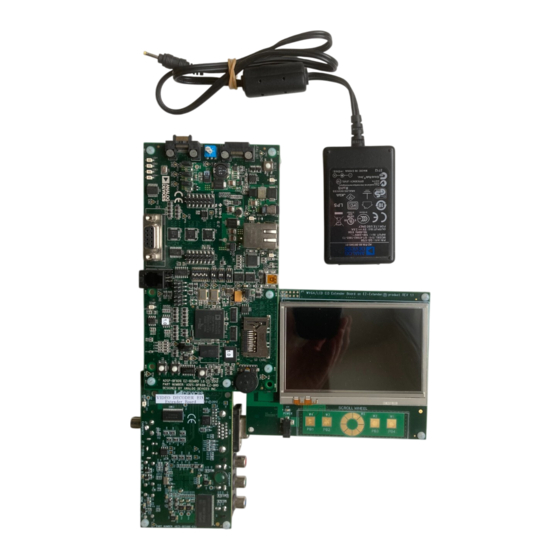
The EZ-Board requires an Analog Devices USB-based emulator (USB, HP-USB, or ICE-100B). Default Configuration The ADSP-BF609 EZ-KIT Lite board is designed to run as a standalone unit. When removing the EZ-KIT Lite board from the package, handle the board carefully to avoid the discharge of static electricity, which can dam- age some components. - Page 24 ) if desired. Place the nylon standoff in the hole and tighten a hex nut on each. Confirm that your board is in the default configuration before using the board. Figure 1-1. EZ-KIT Lite Hardware Setup ADSP-BF609 EZ-KIT Lite Evaluation System Manual...
-
Page 25: Supported Operating Systems
• 2 GHz single-core processor • 1 GB RAM • 8 GB available disk space • One open USB port A faster disk drive decreases the build time, especially for a large amount of source files. ADSP-BF609 EZ-KIT Lite Evaluation System Manual... -
Page 26: Ez-Kit Lite Installation
USB cable. Step 2: Connect the EZ-KIT Lite board to a personal computer (PC) run- ning CCES. There are two connection options: using an Analog Devices emulator or using the standalone debug agent. Using an Emulator: 1. Plug one side of the assembled USB cable into the USB connector of the emulator. -
Page 27: Ez-Kit Lite Session Startup
CCES) to the PC, the Windows driver wizard may not find the board drivers. 1. Navigate to the CCES environment via the Start menu. Note that CCES is not connected to the target board. ADSP-BF609 EZ-KIT Lite Evaluation System Manual... - Page 28 5. Select one of the following: • For standalone debug agent connections, EZ-KIT Lite and click Next. • For emulator connections, Emulator and click Next. The Select Platform page of the Session Wizard appears. ADSP-BF609 EZ-KIT Lite Evaluation System Manual...
- Page 29 Using ADSP-BF609 EZ-KIT Lite 6. Do one of the following: • For standalone debug agent connections, ensure that the selected platform is ADSP-BF609 EZ-KIT Lite via Debug Agent. • For emulator connections, choose the type of emulator that is connected to the board.
-
Page 30: Evaluation License
Evaluation License Evaluation License The ADSP-BF609 EZ-KIT Lite software is part of the Board Support Package (BSP) for the Blackfin ADSP-BF60x family. The EZ-KIT Lite is a licensed product that offers an unrestricted evaluation license for 90 days after activation. Once the evaluation period ends, the evaluation license becomes permanently disabled. - Page 31 Using ADSP-BF609 EZ-KIT Lite Figure 1-2. ADSP-BF609 Processor Memory Map ADSP-BF609 EZ-KIT Lite Evaluation System Manual 1-11...
-
Page 32: Ddr2 Sdram
An example program is included in the EZ-KIT Lite installation directory to demonstrate how to setup and access the DDR2 interface. For more information on how to initialize the registers after a reset, refer to the hardware reference manual. 1-12 ADSP-BF609 EZ-KIT Lite Evaluation System Manual... -
Page 33: Spi Interface
(RMIIs), one of which connects to an external Ethernet PHY device. The EZ-KIT Lite provides a National DP83848C, Auto-MDIX, fully compliant PHY with IEEE 802.2/802.2u standards. The PHY supports 10BASE-T and 100BASE-TX operations. ADSP-BF609 EZ-KIT Lite Evaluation System Manual 1-13... -
Page 34: Usb Otg Hs Interface
Use the example programs in the EZ-KIT Lite installation directory to learn about the processor’s device and host modes. For more information, refer to the ADSP-BF60x Blackfin Processor Hardware Reference. 1-14 ADSP-BF609 EZ-KIT Lite Evaluation System Manual... -
Page 35: Can Interface
The ADSP-BF609 processor has two built-in universal asynchronous transmitters (UARTs), with only connected to a UART line trans- UART0 mitter. has full RS-232 functionality via the Analog Devices UART0 ADM3315 line driver and receiver ( of the processor is connected to the PD07/UART0_TX/TM0_ACI3 ADM3315 device directly. -
Page 36: Sd Interface
The rotary switch is a two-bit quadrature (gray code) counter with detent, meaning that both the down signal ( ) and up signal ( ) tog- CNT0_DG CNT0_UD gle when the count register increases on a rotation to the right. 1-16 ADSP-BF609 EZ-KIT Lite Evaluation System Manual... -
Page 37: Temperature Sensor Interface
ADSP-BF609 processor by default. Thermal Limit LED (LED5) Software-Controlled Switches (Soft- Config) for more information. Example programs are included in the EZ-KIT Lite installation directory to demonstrate temperature sensor operations. ADSP-BF609 EZ-KIT Lite Evaluation System Manual 1-17... -
Page 38: Link Ports Interface
Two push buttons are available on programmable flags PB10 PE01 The push buttons are connected to the processor by default. Use SoftCon- fig to disconnect the push buttons. Refer to Software-Controlled Switches (SoftConfig) for more information. 1-18 ADSP-BF609 EZ-KIT Lite Evaluation System Manual... -
Page 39: Jtag Interface
CCES Target Configurator. Then create a session for the EZ-KIT Lite based on the newly created platform. For a dual ADSP-BF609 EZ-KIT Lite session, connect two EZ-KIT Lites via connectors . Flip one of the two EZ-KIT Lites by 180 degrees to allow the boards to mate. -
Page 40: Power-On-Self Test
EZ-Extender or a custom-design daughter board to be tested across vari- ous hardware platforms that have the same expansion interface. The EI3 implemented on the ADSP-BF609 EZ-KIT Lite consists of five connectors, , and . The connectors contain a major- ity of the processor's signals. -
Page 41: Power Architecture
Additional circuitry can add extra loading to signals, decreasing their max- imum effective speed. Analog Devices does not support and is not responsible for the effects of additional circuitry. Power Architecture The ADSP-BF609 EZ-KIT Lite has three primary voltage domains: 3.3V, 1.25V and 1.8V. -
Page 42: Example Programs
Example Programs Example Programs Example programs are provided with the ADSP-BF609 EZ-KIT Lite to demonstrate various capabilities of the product. The programs are installed with CCES and can be found in the CrossCore Embedded Stu- dio directory. Refer to a readme file provided with each example for more information. -
Page 43: Adsp-Bf609 Ez-Kit Lite Hardware Reference
Shows the locations and describes the LEDs. • Connectors Shows the locations and provides part numbers for the on-board connectors. In addition, the manufacturer and part number infor- mation is provided for the mating parts. ADSP-BF609 EZ-KIT Lite Evaluation System Manual... -
Page 44: System Architecture
The clock rate can be set up on the fly by the processor. The input clock is 25 MHz. The core clock runs at a maximum of 500 MHz. The default boot mode for the processor is parallel flash boot. ADSP-BF609 EZ-KIT Lite Evaluation System Manual... -
Page 45: Software-Controlled Switches (Softconfig)
Software-Controlled Switches (SoftConfig) On the ADSP-BF609 EZ-KIT Lite, most of the traditional mechanical switches have been replaced by I C software-controlled switches. The remaining mechanical switches are provided for setting up a single- or multiprocessor JTAG session, changing the boot mode, and push buttons. - Page 46 EXAMPLE_SIGNAL_B used to change to a logic 1 through software that interfaces with ENABLE_A the Microchip. The same procedure for would disconnect ENABLE_B EXAM- from PLE_SIGNAL_C EXAMPLE_SIGNAL_D Figure 2-2. Example of Individual FET Switches ADSP-BF609 EZ-KIT Lite Evaluation System Manual...
- Page 47 Also notice the default setting for reference designators . In order to connect the letters instead of the numbers, the user physically changes all switches on to the position and all switches on to the position. ADSP-BF609 EZ-KIT Lite Evaluation System Manual...
- Page 48 Software-Controlled Switches (SoftConfig) Figure 2-4. Example of Bus Switch ADSP-BF609 EZ-KIT Lite Evaluation System Manual...
-
Page 49: Softconfig On The Adsp-Bf609 Ez-Kit Lite
ADSP-BF609 EZ-KIT Lite Hardware Reference Figure 2-5. Example of Mechanical Switch Equivalent to Figure 2-4 SoftConfig on the ADSP-BF609 EZ-KIT LITE The Microchip MCP23017 GPIO expander provides control for individ- ual and 10-bit electronic switches. The TWI0 interface of the processor communicates with the Microchip device. -
Page 50: Programming Softconfig Switches
Enabled (except for wake push button) LEDs Enabled Programming SoftConfig Switches On the ADSP-BF609 EZ-KIT Lite, three Microchip MCP23017 devices exist. Each of these devices have the following programming characteristics: • Each switch has two programmable GPIO registers. GPIO Register... - Page 51 C Hardware Address 0x21 GPIO MCP23017 Register Address Default Value GPIOA 0x12 0x07 GPIOB 0x13 0xFC Table 2-3. I C Hardware Address 0x22 GPIO MCP23017 Register Address Default Value GPIOA 0x12 0x0A GPIOB 0x13 0x00 ADSP-BF609 EZ-KIT Lite Evaluation System Manual...
- Page 52 The selection line must be low in order to disconnect the signals from the link port connector . This allows the signals to connect to the on-board parallel flash memory and EI3 connec- tors. See ADSP-BF609 EZ-KIT Lite Schematic for details. 2-10 ADSP-BF609 EZ-KIT Lite Evaluation System Manual...
- Page 53 GPIO PE02 for CAN0 error High CAN0_ERR_EN U33 PE02/SPI1_ RDY/PPI0_ D22/SPT1_ACLK CAN0RX connected to CAN0RX_EN U34 PG04/SPT2_ CAN IC U55 ACLK/TM0_ TMR1/CAN0_ RX/TM0_ACI2 Rotary counter 0 count up CNT0UD_EN U30 PG11/SPT2_ connected to rotary connec- BD1/TM0_ TMR6/CNT0_UD ADSP-BF609 EZ-KIT Lite Evaluation System Manual 2-11...
- Page 54 UART0 CTS and RTS not High UART0CTS_RTS_LPBK connected. Change to low for looping back UART0 CTS and RTS signals UART0 CTS signal not con- High UART0CTS_RST_EN nected to input of reset IC (U48) 2-12 ADSP-BF609 EZ-KIT Lite Evaluation System Manual...
- Page 55 ) is controlling the enable signal of a FET switch. Also note that if a particular functionality of the processor signal is being used, it will be in bold font under the Pro- cessor Signal column. ADSP-BF609 EZ-KIT Lite Evaluation System Manual 2-13...
- Page 56 SLEEP/TM0_ACI4 PE14 is used as GPIO LED3_GPIO_EN PE14/ETH1_ LED3 output for LED3, RXERR/SPT2_ ATDV/TM0_TMR0 enabled by default PB11 is used as GPIO LED4_GPIO_EN PB11/SMC0_ LED4 output for LED4, A25/SPT0_ BD0/TM0_ACLK3 enabled by default 2-14 ADSP-BF609 EZ-KIT Lite Evaluation System Manual...
- Page 57 D16/SPI0_SEL3 This is needed for quad access mode. SPI flash data 3 connec- SPI0D3_EN PD01/SPI0_ tion to U38 SPI flash, D3/PPI1_ connected by default. D17/SPI0_SEL2 This is needed for quad access mode. ADSP-BF609 EZ-KIT Lite Evaluation System Manual 2-15...
- Page 58 ETHERNET_EN U4/U5 signals from U49 Enables push button High WAKE_PUSHBUTTON_EN PE12/ETH1_PHY- input to processor INT/PWM1_ CL/RSI0_D5 Connects processor sig- High PD0_SPI0D2_ PD00/SPI0_ EPPI1D16_SPI0SEL3_ nal to EI3 connectors, D2/PPI1_ EI3_EN D16/SPI0_SEL3 disabled by default 2-16 ADSP-BF609 EZ-KIT Lite Evaluation System Manual...
- Page 59 Component Default (if applicable) Connected Connects processor sig- High PD3_SPI0MOSI_EI3_EN U56 PD03/SPI0_MOSI nal to EI3 connectors, disabled by default Connects processor sig- High PD4_SPI0CK_EI3_EN U58 PD04/SPI0_CLK nal to EI3 connectors, disabled by default ADSP-BF609 EZ-KIT Lite Evaluation System Manual 2-17...
-
Page 60: Push Buttons And Switches
Table 2-11. The default configuration applies to either a debug agent or an external emulator, such as the Analog Devices high-performance USB-based emu- lator (HP-USB) or ICE-100B emulator. To use an external emulator and multiple EZ-KIT Lites simultaneously in one CrossCore Embedded Studio (CCES) multi-processor session, set up... - Page 61 SW1.4 SW1.5 SW1.6 SW1.7 SW1.8 SW3.1 SW3.2 SW4.1 SW4.2 SW5.1 SW5.2 Table 2-12. Multiple-Processor Configuration Switch Position Main EZ-KIT Lite EZ-KIT Lite Attached to Emulator Not Attached to Emulator SW1.1 SW1.2 SW1.3 SW1.4 ADSP-BF609 EZ-KIT Lite Evaluation System Manual 2-19...
-
Page 62: Boot Mode Select Switch (Sw2)
ADSP-BF609 processor boots from 8-bit flash memory (parallel flash boot). Table 2-13. Boot Mode Select Switch (SW2) SW2 Position Processor Boot Mode Idle—no boot Parallel flash boot (default) RSI master boot SPI0 master boot SPI0 slave boot Reserved 2-20 ADSP-BF609 EZ-KIT Lite Evaluation System Manual... -
Page 63: Irq/Flag Enable Switches (Sw6-7)
The rotary encoder is a two-bit quadrature (Gray code) encoder. The rotary encoder can be disconnected from the processor by setting SoftConfig, see Software-Controlled Switches (SoftConfig) for more information. ADSP-BF609 EZ-KIT Lite Evaluation System Manual 2-21... -
Page 64: Wake Push Switch (Sw10)
SoftConfig. Refer to Software-Con- trolled Switches (SoftConfig) for more details. Power Jumpers This section describes functionality of the power jumpers ( P10-15 Figure 2-7 shows the jumper locations. Figure 2-7. Configuration Jumper Locations 2-22 ADSP-BF609 EZ-KIT Lite Evaluation System Manual... -
Page 65: Leds
Table 2-14. Power Jumpers (P10-15) Jumper Power Domain VDD_DMC VDD_INT 3.3V VDD_EXT VDD_USB USB_VBUS LEDs This section describes the on-board LEDs. Figure 2-8 shows the LED locations. Figure 2-8. LED Locations ADSP-BF609 EZ-KIT Lite Evaluation System Manual 2-23... -
Page 66: Gpio Leds (Led1-4)
For more information, see Temperature Sensor Interface. Power LED (LED6) When is lit solid (green), it indicates that power is being supplied to LED6 the board properly. 2-24 ADSP-BF609 EZ-KIT Lite Evaluation System Manual... -
Page 67: Reset Led (Led7)
When is lit (red), it indicates that the master reset of the processor is LED4 active. The reset signal is controlled by the Analog Devices ADM13305 supervisory reset circuit. SPD LED (LED6) SPD LED indicates the speed of the Ethernet port. When... -
Page 68: Dce Uart Connector (J2)
For more information, see JTAG Interface. Remove the standalone debug agent when an emulator is used with the board. Follow the installation instructions provided in EZ-KIT Lite Installation, using as the JTAG connection point. 2-26 ADSP-BF609 EZ-KIT Lite Evaluation System Manual... -
Page 69: Jtag Connector (Zp1)
FX8-120S-SV(21) USB Connector (P7) Part Description Manufacturer Part Number USB mini-Ab MOLEX 56579-0576 Power Connector (P18) Part Description Manufacturer Part Number 0.65 mm power jack 045-0883R Mating Connector 5.0VDC@3.6A power supply GLOBETEK GS-1750(R) ADSP-BF609 EZ-KIT Lite Evaluation System Manual 2-27... -
Page 70: Can Connector (J4)
Standard Ethernet cable Ethernet Connectors (P16-17) allow connection to the Ethernet port IEEE 1588 signals. They are 6-pin 0.1” headers. The pinout of the connectors can be found in ADSP-BF609 EZ-KIT Lite Schematic. 2-28 ADSP-BF609 EZ-KIT Lite Evaluation System Manual... -
Page 71: Adsp-Bf609 Ez-Kit Lite Bill Of Materials
DEVICES 2_1900X1900 ADP1864AUJZ ANALOG ADP1864AUJZ-R7 SOT23-6 DEVICES ADP1715 MSOP8 ANALOG ADP1715ARMZ-1.8-R7 DEVICES 74LVC14A SOIC14 74LVC14AD IDT74FCT3244AP IDT74FCT3244APYG Y SSOP20 SN74LVC1G08 U52-U53 SN74LVC1G08DBVR SOT23-5 TJA1041 SOIC14 TJA1041T/VM,512 SN74LVC1G04 SN74LVC1G04DBVT SOT23-5 SN74CB3Q3245 U4-U5 DIGI-KEY 296-19130-1-ND TSSOP20 ADSP-BF609 EZ-KIT Lite Evaluation System Manual... - Page 72 BF609 MICRON PC28F128P33BF60D PC28F128P33B BF609 W25Q32 WINBOND W25Q32BVSSIG SI7403BDN ICS010 VISHAY SI7403BDN 25MHZ OSC003 DIGI-KEY SG-8002CA-SCB-ND 48MHZ OSC003 DIGI-KEY SG-8002CA-SCB-ND(48.00M) ADP2119ACPZ-R7 ANA00 ADP2119ACPZ-R7 DFN50P300X300-1 DIP8 SWT016 C&K TDA08H0SB1 IDC 3X2 P16-P17 SAMTEC TSM-103-01-T-DV IDC3X2_SMT ADSP-BF609 EZ-KIT Lite Evaluation System Manual...
- Page 73 ADSP-BF609 EZ-KIT Lite Bill Of Materials Ref. Qty. Description Reference Manufacturer Part Number Designator DB9 9PIN CON038 NORCOMP 191-009-213-L-571 RJ11 4PIN TYCO 5558872-1 CON039 DIP2 SWT020 SW3-SW5 C&K CKN9064-ND IDC 2X1 IDC2X1 P10-P15 90726-402HLF 3A RESETABLE TYCO SMD300F-2 FUS004 IDC 2PIN_-...
- Page 74 CRCW08050000Z0EA 190 100MHZ 5A FER4 MURATA DLW5BSN191SQ2 FER002 10UF 6.3V 10% C39,C117-C118, 08056D106KAT2A 0805 C163-C164, C177-C178 4.7UF 6.3V 10% 08056D475KAT2A 0805 0.1UF 10V 10% C17-C18, 0402ZD104KAT2A 0402 C41-C45,C84, C95,C100, C115-C116, C135-C142, C153-C162, C173-C176,C186, C188-C191,C200 ADSP-BF609 EZ-KIT Lite Evaluation System Manual...
- Page 75 ADSP-BF609 EZ-KIT Lite Bill Of Materials Ref. Qty. Description Reference Manufacturer Part Number Designator 0.01UF 16V 10% C1-C15,C19, 0402YC103KAT2A 0402 C22-C24, C26-C38,C40, C46-C61, C64-C83,C94, C96-C98, C104-C107, C111-C113, C119-C134, C143-C152, C165-C172, C179-C185,C192, C198-C199 10K 1/16W 5% R9-R12,R17-R18, VISHAY CRCW040210K0FKED 0402 R20-R33,R39-R48,...
- Page 76 0.0 1/10W 1% 0603 R129,R214-R217 PHYCOMP 232270296001L 10 1/10W 5% 0603 R151-R152,R237 VISHAY CRCW060310R0JNEA 4700PF 16V 10% C110 DIGI-KEY 311-1083-2-ND 0603 100PF 50V 5% 0603 C108-C109 06035A101JAT2A 2.21K 1/10W 1% R186-R187,R191, DIGI-KEY 311-2.21KHRTR-ND 0603 R199,R201-R204, R207-R208 ADSP-BF609 EZ-KIT Lite Evaluation System Manual...
- Page 77 ADSP-BF609 EZ-KIT Lite Bill Of Materials Ref. Qty. Description Reference Manufacturer Part Number Designator 62.0 1/10W 1% R153-R154 DIGI-KEY 311-62.0HRTR-ND 0603 1UF 6.3V 20% 0402 C62-C63,C93 PANASO- ECJ-0EB0J105M 100 1/16W 5% R87-R88,R141 DIGI-KEY 311-100JRTR-ND 0402 24.9K 1/10W 1% R132 DIGI-KEY 311-24.9KHTR-ND...
- Page 78 SOT23-3 30A GSOT03 D3-D4 VISHAY GSOT03-GS08 SOT23-3 40A ESD5Z2.5T1 ON SEMI ESD5Z2.5T1G SOD-523 165.0 1/10W 1% R197-R198 DIGI-KEY P165HTR-ND 0603 220.0 1/10W 1% R185 DIGI-KEY P220HTR-ND 0603 4.87K 1/10W 1% R189 DIGI-KEY 541-4.87KHCT-ND 0402 ADSP-BF609 EZ-KIT Lite Evaluation System Manual...
- Page 79 ADSP-BF609 EZ-KIT Lite Bill Of Materials Ref. Qty. Description Reference Manufacturer Part Number Designator 49.9 1/16W 1% R176-R184,R193- STACK- RMCF0402FT49R9 0402 R196 POLE 15KV ESD7004 ON SEMI ESD7004MUTAG DFN50P250X100-1 15KV ESDA6V1SC DIGI-KEY 497-6637-1-ND SOT95P280-6N 30K 1/10W 1% R242 PANASO- ERJ-2RKF3002X 0402 32.4K 1/10W 1%...
- Page 80 A-10 ADSP-BF609 EZ-KIT Lite Evaluation System Manual...
- Page 81 ADSP-...
- Page 82 DMC0_BA2_Z DMC0_BA2 DMC0_CK DMC0_CK DMC0_CK DMC0_CK DMC0_CKE DMC0_CKE_Z DMC0_CAS DMC0_CAS_Z DMC0_RAS DMC0_RAS_Z DMC0_WE DMC0_WE_Z DMC0_ODT DMC0_ODT_Z VREF_DMC VREF_DMC ADSP-BF609 BGA349C80P22X22_1900X1900 0.1UF 0402 DMC0_A10_Z DMC0_A10 DMC0_DQ03_Z DMC0_A12_Z DMC0_A12 DMC0_DQ04_Z DMC0_A07_Z DMC0_A07 DMC0_DQ05_Z DMC0_A01_Z DMC0_A01 DMC0_DQ02_Z RNS005 RNS005 DMC0_A05_Z DMC0_A05 DMC0_DQ07_Z DMC0_A11_Z DMC0_A11 DMC0_DQ06_Z DMC0_A13_Z...
- Page 83 PB07/SMC0_A22/PPI2_D16/SPT0_BFS PB07/SMC0_A22/PPI2_D16/SPT0_BFS PB08/SMC0_A23/PPI2_D17/SPT0_BCLK PB08/SMC0_A23/PPI2_D17/SPT0_BCLK PB09/SMC0_BGH/SPT0_AD0/TM0_ACLK2 PB09/SMC0_BGH/SPT0_AD0/TM0_ACLK2 PD09/SPI PB10/SMC0_A24/SPT0_BD1/TM0_ACLK0 PB10/SMC0_A24/SPT0_BD1/TM0_ACLK0 PD10/SPI PB11/SMC0_A25/SPT0_BD0/TM0_ACLK3 PB11/SMC0_A25/SPT0_BD0/TM0_ACLK3 PB12/SMC0_BG/SPT0_BTDV/SPT0_AD1/TM0_ACLK1 PB12/SMC0_BG/SPT0_BTDV/SPT0_AD1/TM0_ACLK1 PD12/SPI1_SEL1/P PB13/ETH0_TXEN/PPI1_FS1/TM0_ACI6 PB13/ETH0_TXEN/PPI1_FS1/TM0_ACI6 PB14/ETH0_REFCLK/PPI1_CLK PB14/ETH0_REFCLK/PPI1_CLK PB15/ETH0_PTPPPS/PPI1_FS3 PB15/ETH0_PTPPPS/PPI1_FS3 PD15/S ADSP-BF609 BGA349C80P22X22_1900X1900 PE00/SPI1_D3/PPI0_D18/SPT1_BD1 PE00/SPI1_D3/PPI0_D18/SPT1_BD1 PE01/SPI1_D2/PPI0_D19/SPT1_BD0 PE01/SPI1_D2/PPI0_D19/SPT1_BD0 PE02/SPI1_RDY/PPI0_D22/SPT1_ACLK PE02/SPI1_RDY/PPI0_D22/SPT1_ACLK PE03/PPI0_D16/ACM0_FS/SPT1_BFS PE03/PPI0_D16/ACM0_FS/SPT1_BFS PE04/PPI0_D17/ACM0_CLK/SPT1_BCLK PE04/PPI0_D17/ACM0_CLK/SPT1_BCLK PG04/SPT2_ACL PE05/PPI0_D23/SPT1_AFS PE05/PPI0_D23/SPT1_AFS PG05/ETH1_TXEN/R PE06/SPT1_ATDV/PPI0_FS3/LP3_CLK PE06/SPT1_ATDV/PPI0_FS3/LP3_CLK PG06/ETH1_REFCLK/RSI0 PE07/SPT1_BTDV/PPI0_FS2/LP3_ACK PE07/SPT1_BTDV/PPI0_FS2/LP3_ACK...
- Page 84 VDD_EXT23 VDD_INT23 VDD_EXT24 VDD_INT24 VDD_DMC VDD_EXT25 VDD_DMC1 VDD_EXT26 VDD_DMC2 VDD_EXT27 VDD_DMC3 VDD_EXT28 VDD_DMC4 VDD_USB VDD_EXT VDD_EXT29 VDD_DMC5 R165 VDD_EXT30 VDD_DMC6 0402 VDD_TD VDD_TD VDD_DMC7 VDD_DMC8 VDD_USB VDD_DMC9 VDD_DMC10 C114 C115 C116 VDD_DMC11 10UF 0.1UF 0.1UF 0805 0402 0402 VDD_DMC12 VDD_DMC13 VDD_DMC14 VDD_DMC15 VDD_DMC16...
- Page 85 0402 0402 SYS_EXTWAKE STANDBY SYS_CLKIN 25MHZ 3.3V OSC003 TP10 0.01UF 0402 VBUS "USB OTG" SHELL CON052 USB_MINI-AB OPTIONAL DSP CRYSTAL R212 25MHz 0402 OSC013 0402 SYS_XTAL SYS_CLKIN 18PF 18PF 0402 0402 R162 0402 SYS_EXTWAKE...
- Page 86 PA14/SMC0_A19/PPI2_D14 PA15/SMC0_A20/PPI2_D15 WAIT PB06/SMC0_A21/SPT0_ATDV/TM0_ACLK4 PB07/SMC0_A22/PPI2_D16/SPT0_BFS PB08/SMC0_A23/PPI2_D17/SPT0_BCLK PB10/SMC0_A24/SPT0_BD1/TM0_ACLK0 SMC0_AMS0 SMC0_ARE SMC0_AWE SYS_NMI/SYS_RESETOUT SMC0_AOE/SMC0_NORDV VPEN PB00/SMC0_NORCLK/PPI2_CLK PC28F128P33B R223 EBGA64 0402 32Mb QUAD SPI FLASH 3.3V 0402 0402 0402 0402 0402 PD03/SPI0_MOSI PD04/SPI0_CLK SPIFLASH_CS SPIFLASH_SPI0D2 SPIFLASH_SPI0D3 HOLD 3.3V W25Q32 SO8W 0402 0.01UF 0402...
- Page 87 3.3V 0402 0402 0402 UART0CTS_EN PD10/SPI0_RDY/UART0_CTS/SPI1_SEL3 PI3A125 SC70_5 UART0CTS_RTS_LPBK PI3A125 SC70_5 UART0CTS_RST_EN PI3A125 SC70_5 3.3V 0.01UF 0.01UF 0.01UF 0.01UF 0.01UF 0.01UF 0402 0402 0402 0402 0402 0402...
- Page 88 CNT0UD_EN PG11/SPT2_BD1/TM0_TMR6/CNT0_UD PI3A125 SC70_5 CNT0DG_EN PG12/SPT2_BD0/TM0_TMR7/CNT0_DG PI3A125 SC70_5 CNT0ZM_EN PG07/SPT2_BFS/TM0_TMR5/CNT0_ZM PI3A125 SC70_5 R158 R159 R160 0402 0402 0402...
- Page 89 R169 0402 SNI_MODE ET0CRS_Z SYS_HWRS 3.3V PHY_PWR_DWN_INT PHY_CLKIN R182 49.9 PC02/ETH0_TXD0/PPI1_D02 ET0TXD0_Z 0402 R183 49.9 PC03/ETH0_TXD1/PPI1_D03 ET0TXD1_Z 0402 R184 49.9 PB13/ETH0_TXEN/PPI1_FS1/TM0_ACI6 ET0TXEN_Z 0402 PD06/ETH0_PHYINT/PPI1_FS2/TM0_ACI5 PD06/ETH0_PHYINT_Z ETHERNET_EN SN74CB3Q3245 TSSOP20 3.3V R170 0402 PD06/ETH0 C179 C180 0.01UF 0.01UF 0402 0402 3.3V 3.3V 3.3V R171 PHY OSC...
- Page 90 JTAG SWITCHES "JTAG" TRST_LOCAL JTG_TRST 0402 0402 TRST_LINKPORT EMU_LOCAL JTG_EMU EMU_LOCAL EMU_LINKPORT TMS_LOCAL JTG_TMS TMS_LOCAL TMS_LINKPORT TCK_LOCAL TCK_LOCAL JTG_TCK TRST_LOCAL TCK_LINKPORT DIP8 TDI_LOCAL SWT016 TDO_LOCAL IDC7x2_SMTA JTG_TDI TDI_LOCAL DIP2 4.7K SWT020 0402 JTG_TDO TDO_LOCAL TDO_OUT DIP2 SWT020 JTG_TDI TDO_IN TDO_LOCAL TDO_IN DIP2 SWT020...
- Page 91 0402 LABEL "PB1" PUSHBUTTON1_EN 0402 0402 PB10/SMC0_A24/SPT0_BD1/TM PI3A125 74LVC14A MOMENTARY SC70_5 SOIC14 SWT024 0402 0402 0402 LABEL "PB2" PUSHBUTTON2_EN 0402 0402 PE01/SPI1_D2/PPI0_D19/SPT1_ PI3A125 74LVC14A MOMENTARY SC70_5 SOIC14 SWT024 0402 0402 3.3V 3.3V R142 0402 0402 R141 R140 WAKE_P 0402 0402 PE12/ETH SW10 PI3A125...
- Page 92 OVERRIDE_SMC0_ BOOT[0] SMC0_LP0_EN U41 output LP0_BOOT SMC0_EPPI2 SMC0_EPPI2 U41 output selection table PA00 PA01 PA02 PA03 OVERRIDE_SMC0_LP0_BOOT OVERRIDE_EBIU_LP0_BOOT PA04 74LVC14A PA05 SOIC14 3.3V PA06 PA07 PB00/SMC0 PB01/SMC0 R108 3.3V 0402 OVERRIDE_SMC0_LP0_BOOT SYS_MODE0 PI3A125 SC70_5 R116 0402 OVERRIDE_EBIU_LP0_BOOT U41_SEL SMC0_LP0_EN PI3A125 SC70_5 R117 R109...
- Page 93 PD2_SPI0MISO_EI3 SPI0_MISO SPI0_MOSI PD3_SPI0MOSI_EI3 PD0_SPI0D2_EPPI1D16_SPI0SEL3_EI3 SPI0_D2 SPI0_D3 PD1_SPI0D3_EPPI1D1 PD11/SPI0_SEL1/SPI0_SS SPI0_SEL1/SPI0_SS* SPI0_SEL_A PC15/SPI0_SEL4/PPI1_ PC12/SPI0_SEL7/PPI1_D12 SPI0_SEL_B SPI0_SEL_C PD09/SPI0_SEL5/UART EXT_BOOT R118 TWI0_A0* 0402 TWI0_SCL SCL0* SCL1* TWI1_SCL TWI0_SDA SDA0* SDA1* TWI1_SDA PE00/SPI1_D3/PPI0_D18/SPT1_BD1 GPIO0 GPIO1 PE01/SPI1_D2/PPI0_D PE03/PPI0_D16/ACM0_FS/SPT1_BFS GPIO2 GPIO3 PE04/PPI0_D17/ACM0 PE14/ETH1_RXERR/SPT2_ATDV/TM0_TMR0 GPIO4 GPIO5 PG02/ETH1_TXD1/PW PG03/ETH1_TXD0/PWM1_AH/RSI0_D0 GPIO6 GPIO7*...
- Page 94 PD09/SPI0_SEL5/UART0_RTS/SPI1_SEL4 SPI1_SEL_B SPI1_SEL_C PC14/SPI1_SEL7/PPI1_D14 R119 TWI0_A0* 0402 TWI0_SCL SCL0* SCL1* TWI1_SCL TWI0_SDA SDA0* SDA1* TWI1_SDA PE00/SPI1_D3/PPI0_D18/SPT1_BD1 GPIO0 GPIO1 PE01/SPI1_D2/PPI0_D19/SPT1_ PE03/PPI0_D16/ACM0_FS/SPT1_BFS GPIO2 GPIO3 PE04/PPI0_D17/ACM0_CLK/SP PE14/ETH1_RXERR/SPT2_ATDV/TM0_TMR0 GPIO4 GPIO5 PG02/ETH1_TXD1/PWM1_AL/R PG03/ETH1_TXD0/PWM1_AH/RSI0_D0 GPIO6 GPIO7* PG13/UART1_CTS/TM0_CLK PE14/ETH1_RXERR/SPT2_ATDV/TM0_TMR0 TMR_A TMR_B PG04/SPT2_ACLK/TM0_TMR1/C PG01/SPT2_AFS/TM0_TMR2/CAN0_TX TMR_C TMR_D* PG08/SPT2_AD1/TM0_TMR3/PW PG14/UART1_RX/SYS_IDLE1/TM0_ACI1 UART1_RX UART1_TX PG15/UART1_TX/SYS_IDLE0/SY...
- Page 95 PE01/SPI1_D2/PPI0_D19/SPT1_BD0 SPI2_D2 SPI2_D3 PE00/SPI1_D3/PPI0_D18/SPT1_BD1 PD12/SPI1_SEL1/PPI0_D20/SPT1_AD1/SPI1_SS SPI2_SEL1/SPI2_SS* SPI2_SEL_A PD10/SPI0_RDY/UART0_CTS/SPI1_SEL3 PD09/SPI0_SEL5/UART0_RTS/SPI1_SEL4 SPI2_SEL_B SPI2_SEL_C PC14/SPI1_SEL7/PPI1_D14 TWI0_SCL SCL0* SCL1* TWI1_SCL TWI0_SDA SDA0* SDA1* TWI1_SDA PE00/SPI1_D3/PPI0_D18/SPT1_BD1 GPIO0 GPIO1 PE01/SPI1_D2/PPI0_D19/SPT1_BD0 PE03/PPI0_D16/ACM0_FS/SPT1_BFS GPIO2 GPIO3 PE04/PPI0_D17/ACM0_CLK/SPT1_BCLK PE14/ETH1_RXERR/SPT2_ATDV/TM0_TMR0 GPIO4 GPIO5 PG02/ETH1_TXD1/PWM1_AL/RSI0_D1 PG03/ETH1_TXD0/PWM1_AH/RSI0_D0 GPIO6 GPIO7* PG13/UART1_CTS/TM0_CLK PE14/ETH1_RXERR/SPT2_ATDV/TM0_TMR0 TMR_A TMR_B PG04/SPT2_ACLK/TM0_TMR1/CAN0_RX/T PG01/SPT2_AFS/TM0_TMR2/CAN0_TX TMR_C TMR_D*...
- Page 96 10UF 10UF 1210 0805 0.144 0.144 0.144 0.144 0.144 0.144 PGND R132 24.9K 0603 COMP 470PF 68PF PGATE 0603 0603 R131 ADP1864AU 80.6K SOT23-6 0603 PGND R130 255.0K PGND 0603 0.1UF 0402 1.25V @ 1.5A R237 0603 1.5U PVIN R240 0402 SYNC/MODE R239...
- Page 97 2-26 example programs, 1-22 J3 and P8 (Link Port / JTAG), 2-26 expansion interface, 1-20, 2-27 J4 (CAN), 2-28 J5 (SD), 2-28 P16-17 (ethernet), 2-28 P18 (power), 2-27 FET switches, P1A-C (expansion), 2-27 example, ADSP-BF609 EZ-KIT Lite Evaluation System Manual...
- Page 98 1-13 mechanical switch, 2-5, SoftConfig memory map, of this EZ-KIT Lite, 1-10 on the EZ-KIT Lite, 2-7, 2-11 Micro Signal Architecture (MSA), overview, programming switches, LEDs (LED6), 2-25 notation conventions, xviii SPI interface, 1-13 ADSP-BF609 EZ-KIT Lite Evaluation System Manual...
- Page 99 EZ-KIT Lite, system requirements, technical support, temperature sensor interface, 1-17 thermal limit LED (LED5), 2-24 UART interface, 1-15 USB connector (P7), 2-27 USB OTG HS interface, 1-14 wake push switch (SW10), 2-22 ADSP-BF609 EZ-KIT Lite Evaluation System Manual...
- Page 100 Index ADSP-BF609 EZ-KIT Lite Evaluation System Manual...
- Page 101 Development Boards & Kits - Other Processors Click to view products by manufacturer: Analog Devices Other Similar products are found below : EVB-MEC1418MECC 20-101-1252 C29XPCIE-RDB CC-ACC-18M433 MAX1464EVKIT RTE510Y470TGB00000R RTK0EN0001D01001BZ MAXQ622-KIT# YR0K505231S000BE YR0K50571MS000BE YQB-R5F1057A-TB QB-R5F104PJ-TB CC- ACC-ETHMX OV-7604-C7-EVALUATION-BOARD SK-AD02-D62Q1747TB SK-BS01-D62Q1577TB ST7MDT1-EMU2 GROVE BASE...
Need help?
Do you have a question about the ADSP-BF609 EZ-KIT Lite and is the answer not in the manual?
Questions and answers