Deckma Hamburg OMD-2008 Series Instruction Manual
15ppm bilge alarm
Hide thumbs
Also See for OMD-2008 Series:
- Instruction manual (29 pages) ,
- Instruction manual (41 pages)
Table of Contents
Advertisement
Quick Links
Advertisement
Chapters
Table of Contents

Related Manuals for Deckma Hamburg OMD-2008 Series


Summary of Contents for Deckma Hamburg OMD-2008 Series
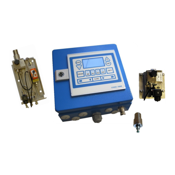
- Page 1 I N S T R U C T I O N M A N U A L OMD-2008 Series 15ppm Bilge Alarm OMD-2008 Series OMD-2008 Electric Valve – OMD-2008 EV Electric Valve Auto Clean – OMD-2008 EVA ...
-
Page 2: Usage Of This Instruction Manual
This instruction manual will guide you how to use the OMD-2008 Series. The instruction manual is split into sections. Every section handles a specific part of the OMD-2008 Series. The first section gives you general information about safety before using and servicing the OMD-2008 Series. -
Page 3: Safety Hazard
Safety hazard Mechanical Risks While closing the front cover hand injuries could be possible. Risk of hand injuries Electrical Risks Incorrect commissioning and wiring, touching live parts, and cable breakage or faulty components can lead to electrical hazards. Electrical voltage warnings Thermal Risk High temperatures can occur on the surface of the measuring cell. - Page 4 15 ppm Bilge Alarm. The OMD-2008 Series are designed in that way, that only the Measuring Cell needs to be changed, as these units carry the Calibration Certificate. The Calibration Certificate with the date of the last calibration check should be retained onboard for inspection purposes.
-
Page 5: Table Of Contents
Content: Usage of this instruction manual ..................1 Disposal ..............................1 Symbols ..............................1 Safety hazard ......................... 2 Risk reduction ............................2 Revision ..............................7 Introduction ......................8 Important Notes ...................... 10 Principle of operation ....................11 Touch Panel..........................11 Measuring Principle ........................ - Page 6 Auto Clean Control Unit ......................48 11.5.1 Pressure Regulation ..........................49 11.5.2 Using standard drainage SS ........................ 49 12. OMD-2008 Series Operating instructions ..............50 12.1 Cleaning Options ........................51 13. Operator Maintenance ..................... 52 13.1 General Test ..........................52 13.2...
- Page 7 Calibration and Repeatability Check ..................63 17.3 Function Test at Classification Survey and Port State Control ..........64 18. OMD-2008 Series with 5 ppm Alarm Set Point ............65 19. Spare Parts ......................66 19.1 Recommended on Board Spares ....................68 20.
-
Page 8: Revision
Servicing and Cleaning Manual ....................82 Index ..........................95 List of Figures ........................96 Sales & Service Locations .................. 97 Type Approved by: ...................... 98 Revision Document-Name Revision No. Notation Date OMD-2008 Series R04_20220318 21.03.2022 Page: 7 of 102... -
Page 9: Introduction
Device preventing overboard discharge, should be as short as possible and in any case not more than 20 s. Mount the OMD-2008 Series instrument by means of M6 or M8 screws on to a rigid vertical surface or frame and preferably with the display panel of the monitor at user convenience. - Page 10 Care must be taken at mounting of the pipes connections to avoid any torsion of the housing and damage of the instrument. For separator discharge pipes, up to 75 mm OD a standard "T"-type junction of the welded or screwed type is satisfactory for the tapping point. For the separator discharge pipes of 80 mm OD and above a sample probe should be employed which protrudes into the discharge piping by approx.
-
Page 11: Important Notes
Important Notes a) This equipment must be installed and operated in strict accordance with the instructions contained in this instruction manual. Failure to do so will impair the protection provided. b) Installation and servicing must be undertaken by a competent and suitably skilled person. -
Page 12: Principle Of Operation
Principle of operation Touch Panel The OMD-2008 Series Touch Display consists of several buttons and LEDs. Each button/ LED has its own specific function. button OK button AL1/2 button/ SYS button/ LED SET button Arrow Slider LOG button TEST button... -
Page 13: Alarms
Alarms The units contain two independent oil alarm circuits. From the manufacturing both alarms are set to 15 ppm (according IMO). The set points can be changed according to the requirements on site, to any point between 1 ppm and 15 ppm. An alarm point setting above 15 ppm is not possible. -
Page 14: Limited Adjustment Alarm Set Point
By request units with alarm set point of 5 ppm max. are available. (For more information, read section 18. OMD-2008 Series with 5 ppm Alarm Set Point). Active Current Interface The active current interface represents a combination of measurements and interpretations. -
Page 15: Automatic Cell Cleaning Device
Cleaning Unit allows to clean the Sample Glass Tube without opening the Cell Cap, and without interrupting the normal sample flow. Maintenance is made easier with the MCU. Please note that operating the MCU may set the instrument to alarm condition for a few seconds. 3.12 Features OMD-2008 Series OMD-2008 OMD-2008 OMD-2008 OMD-2008... -
Page 16: Specification Internal Clock
3.13 Specification Internal Clock The IMO resolution MEPC.107(49) requires the 15 ppm Bilge Alarm to record Date, Time, Alarm Status, and “Separator Status”. To do so, the instrument has an internal clock. The internal clock circuitry is “state of the art”, with only a few ppm derivations over the entire range of operational conditions. -
Page 17: Omd-2008
OMD-2008 The OMD-2008 is the basic version of the OMD-2008 Series. It is equipped with a manual Valve Handle to switch from sample stream to clean water. Page: 16 of 102... -
Page 18: Specification Omd-2008
Specification OMD-2008 Range: 0 – 30 ppm, Trend indication 50 ppm Accuracy: According IMO MEPC. 107(49) Linearity: 0 – 30 ppm better than ± 2 % Display: Yellow Graphic Display Power Supply: 24 V – 240 V AC or DC Automatic Voltage selection Consumption: <... -
Page 19: Omd-2008 Construction
OMD-2008 Construction The OMD-2008 consists of a Computer Unit and a Measuring Cell, which is equipped with a Valve Assembly. All components are mounted on one support. The valve handle controls sample water flow and clean water usage. Figure 2. Construction OMD-2008 Computer Unit Valve Handle Desiccator Cap... -
Page 20: Omd-2008 Installation
OMD-2008 Installation Please refer to the following drawing for mounting dimensions. Figure 3. Installation OMD-2008 Page: 19 of 102... -
Page 21: Omd-2008 Piping
OMD-2008 Piping Connect the OMD-2008 Monitor to the sample point of the oily-water separator outlet and to a source of oil free water employing 6 mm OD copper or stainless-steel pipe. The sampling point should be located on a vertical section of the separator outflow piping to minimize the effects of any entrained air. -
Page 22: Omd-2008 Cabling
OMD-2008 Cabling The following figures illustrate a bottom view of the OMD-2008 Computer Units as delivered. Use one of the M20 opening for the power supply voltage. Remove the plastic screw to attach the cable gland. Further openings can also be used with a cable gland. Figure 5. -
Page 23: Omd-2008 Ev
OMD-2008 EV The OMD-2008 EV is designed with an Electric Switchover Valve to switch the instrument from sample stream to supply of clean, oil free water. The instrument will switch over to alarm condition but will also continue to display the measurement result. The Electric Switchover Valve also allows remote flushing. -
Page 24: Specification Omd-2008 Ev
Specification OMD-2008 EV Range: 0 – 30 ppm, Trend indication 50 ppm Accuracy: According IMO MEPC. 107(49) Linearity: 0 – 30 ppm better than ± 2 % Display: Yellow Graphic Display Power Supply: 24 V – 240 V AC or DC Automatic Voltage selection Consumption: <... -
Page 25: Construction Omd-2008 Ev
Construction OMD-2008 EV The OMD-2008 EV consists of a Computer Unit, and a Measuring Cell, which is equipped with an Electric Valve Assembly. All components are mounted on one baseplate. The Electric Valve controls sample water flow and clean water usage. The EV Valve is controlled from the Computer Unit. -
Page 26: Installation Omd-2008 Ev
Installation OMD-2008 EV Please refer to the following drawing for mounting dimensions. The Connector on top of the valve must not be removed under any circumstances, as that requires the breaking of the seal. Figure 7. Installation OMD-2008 EV Page: 25 of 102... -
Page 27: Piping Omd-2008 Ev
Piping OMD-2008 EV Connect the Sample line to the left side input of the OMD-2008 EV. Connect the clean water line to the right-hand side input of the valve. Both inputs have 1/4” female threads. It is recommended to employ 6 mm OD copper or stainless-steel pipe. If possible, it is recommended to install a manual valve into the clean water line next to the OMD-2008 EV. -
Page 28: Cabling Omd-2008 Ev
Cabling OMD-2008 EV Figure 9. Bottom View: OMD-2008 EV Page: 27 of 102... -
Page 29: Omd-2008 Eva
OMD-2008 EVA The OMD-2008 EVA is fitted with an Electric Switchover Valve and an Automatic Cell Cleaning Device. Page: 28 of 102... -
Page 30: Specification Omd-2008 Eva
Specification OMD-2008 EVA Range: 0 – 30 ppm, Trend indication 50 ppm Accuracy: According IMO MEPC. 107(49) Linearity: 0 – 30 ppm better than ± 2 % Display: Yellow Graphic Display Power Supply: 24 V – 240 V AC or DC Automatic Voltage selection Consumption: <... -
Page 31: Construction Omd-2008 Eva
Construction OMD-2008 EVA The OMD-2008 EVA consists of a Computer Unit, and a Measuring Cell, which is equipped with an EV-Valve and Automatic Cell Cleaning Device. Additionally, the components of the OMD-2008 EVA are mounted onto three separate supports. The Automatic Cell Cleaning Device is electrically inserted between the Computer Unit and the Measuring Cell. -
Page 32: Installation Omd-2008 Eva
Installation OMD-2008 EVA The OMD-2008 EVA is fitted with the Auto Clean System. Installation of the OMD-2008 EVA can be carried out in a few steps. Please refer to the following drawing for mounting dimensions. Install the Air Regulation Filter Unit close enough to the OMD-2008 EVA for connection of the air pipe. -
Page 33: Piping Omd-2008 Eva
Piping OMD-2008 EVA Connect the Sample line to the left side input of the OMD-2008 EVA. Connect the clean water line to the right-hand side input of the valve. Both inputs have 1/4” female threads. It Is recommended to employ 6 mm OD copper or stainless-steel pipe. If it is possible, install a manual valve into the clean water line next to the OMD-2008 EVA. -
Page 34: Cabling Omd-24 Eva
Cabling OMD-24 EVA Figure 13. Bottom View: OMD-2008 EVA The OMD-2008 EVA is in tandem with the Automatic Cell Cleaning Device. The Automatic Cell Cleaning Device is connected with the Measuring Cell with another cable. Page: 33 of 102... -
Page 35: Omd-2008 Evfc
OMD-2008 EVFC The OMD-2008 EVFC is equipped with an Electric Switchover Valve for clean water usage and a Flow Sensor, to monitor the sample flow rate through the Measuring Cell. Page: 34 of 102... -
Page 36: Specification Omd-2008 Evfc
Specification OMD-2008 EVFC Range: 0 – 30 ppm, Trend indication 50 ppm Accuracy: According IMO MEPC. 107(49) Linearity: 0 – 30 ppm better than ± 2 % Display: Yellow Graphic Display Power Supply: 24 V – 240 V AC or DC Automatic Voltage selection Consumption: <... -
Page 37: Construction Omd-2008 Evfc
Construction OMD-2008 EVFC OMD-2008 EVFC consists of a Computer Unit, and a Measuring Cell, which is equipped with the EV Flow Control assembly. The components are mounted onto two separate supports. Figure 14. Construction OMD-2008 EVFC 1. Computer Unit 4. EV Valve Connector 7. -
Page 38: Installation Omd-2008 Evfc
Installation OMD-2008 EVFC Computer Unit and Measuring Cell assembly should be mounted close to each other. Please refer to the following drawing for mounting dimensions. Figure 15. Installation OMD-2008 EVFC Pipe connections are prepared for 10mm OD stainless steel (clean water) and 6 mm OD stainless steel or copper pipes (sample water/ outlet). -
Page 39: Piping Omd-2008 Evfc
Piping OMD-2008 EVFC Connect the OMD-2008 EVFC Monitor to the sample point of the oily-water separator outlet and to a source of oil free water. Fittings on the instrument are for 10mm OD stainless steel (clean water) and 6 mm OD stainless steel or copper pipes (sample water/ outlet). -
Page 40: Cabling Omd-2008 Evfc
Cabling OMD-2008 EVFC Figure 17. Bottom View: OMD-2008 EVFC The OMD-2008 EVFC is connected with a y-cable to the Measuring Cell and the Flow Sensor. Page: 39 of 102... -
Page 41: Cleaning Devices
Cleaning Devices Optional item if fitted. There are two optional Cleaning Units available. Both allow routine cleaning of the Sample Glass Tube. They are different in the way they are operated. Manual Cleaning Unit (MCU)/ Automatic Cell Cleaning Device The Automatic Cell Cleaning Device is driven pneumatically, while the Manual Cell Cleaning Unit has to be operated by hand. -
Page 42: Terminal Description
Terminal description POWER SUPPLY MUST HAVE A FUSE T2A POWER SUPPLY 24V-240V AC/DC. EXAMPLE Connections may vary with different separator control boxes. Terminals Nomination Power Supply Pilot Voltage Output (Same as Power Supply) Potential free Output Alarm 1 (Change over contact) 8-10 Potential free Output Alarm 2 (Change over contact) 11-12... - Page 43 Precise wiring details will vary dependent upon the control system to be employed but the most frequently used systems employ alarm relay 1 for alarm only and alarm relay 2 for overboard valve purposes. Electrical connections are made to the terminal blocks inside the computer housing. Wires are connected to the terminals by pushing a suitable screwdriver into the clamp holes to release the internal spring-loaded clamps.
-
Page 44: External Control System
As replacement to a MEPC.60(33) approved separator and no “Status Separator” signal is available. Terminals 17&18 are for signal output of 0(4) to 20 mA. These are active outputs with an open-load voltage about 5 V. And it is recommended not to exceed the 150 external load. -
Page 45: Power Supply
Power Supply (See Section 2. Important Notes). The unit is designed for a power supply of 24 V to 240 V AC or DC. It has an automatic voltage selection. The power supply must have a fuse rated no more than 2A. Page: 44 of 102... -
Page 46: Commissioning
Commissioning For operating and servicing on board, please carefully read the instruction manual and ensure, that the safety recommendations are considered. Read important notice as well. Ensure that wires are correctly connected to the terminal blocks inside the computer housing and ensure that the connection to the Measuring Cell is in place (refer to Figure 2. -
Page 47: Instrument Start-Up Sequence
15 sec. After that time, it will change to the “normal operation” display, showing the actual measurement as shown below in Figure 21. Analyzing Display: and Figure 22. Normal Operation Display. DECKMA HAMBURG Figure 22. Normal Operation Display Figure 21. Analyzing Display: DECKMA HAMBURG Allow a period of time for water entering the Sample Glass Tube. -
Page 48: Figure 23. Flow Rate Adjustment Cell Cap
Flow rate adjustments can be made by Cell Cap, MCU or the Automatic Cell Cleaning Device. Adjust the flow rate through the unit by using the O-Rings in the normal Cell Cap. Low Flow: Let all three O-Rings inside the cap. Medium Flow: Take out the inside O-Ring 4.5x2. -
Page 49: System Settings
11.4 System Settings At commissioning, alarm set points and alarm delays can be set. The signal output can be modified from 0 – 20 mA or 4 to 20 mA. According to external requirements also the offset can be set from -5 ppm to 5 ppm. Also, the settings can be reset to the factory default values, if needed. -
Page 50: Pressure Regulation
The Automatic Cell Cleaning Unit will not work without sufficient supply of pressurized instrumentation air. Make sure, that an air supply is installed. Further check, that the pipes are fixed correctly. Set the Air Regulator (A) output pressure to a pressure of approximately 4 - 6 bar. -
Page 51: Omd-2008 Series Operating Instructions
OMD-2008 Series Operating instructions When oily water flows through the instrument the oil content will be measured and the display will show the actual value of oil content. If the oil concentration exceeds the adjusted threshold (works adjustment 15 ppm), the alarm indicator 1 will be illuminated in intervals during the selected time delay before it changes to steady light and the associated alarm relay will operate. -
Page 52: Cleaning Options
The OMD-2008 EV units have an electric switchover valve to switch over from sample water to fresh water. Any operation is triggered via the front panel, or triggered remotely, by an external dry contact (see terminals 19&20). The units will be in alarm condition, if fresh water is opened. -
Page 53: Operator Maintenance
Operator Maintenance (See Section 2. Important Notes). WEEKLY INTERVALS: 13.1 to 13.6 Data Logger Checking MONTHLY INTERVALS: 13.7 MCU and Automatic Cell Cleaning Device The Operator Maintenance should be scheduled at least once a week. If needed, prepare the Quick Check List to keep track on maintenance. For more information, see section 24.1 Operator Maintenance Quick Checklist. -
Page 54: Cleaning Process
13.3 Cleaning Process g) Stop any water flow. For instruments equipped with Automatic Cell Cleaning Device, shut off the instrument air. h) Unscrew and remove the Cell Cap. Visually check the wiper piston and the O - Rings for wear or damage. i) The wiper seal should be clean. -
Page 55: Data Logger Checking
13.6 Data Logger Checking t) Check the data logger: 1. Is the data logger recording the data? 2. Check the clock for time deviation. For more information, see section: 14. Programming Mode. 13.7 MCU and Automatic Cell Cleaning Device a) Stop water flow and air supply, respectively. b) Check the wiper seal and the O-Rings. -
Page 56: Maintenance Recommendations
13.8 Maintenance Recommendations Maintenance recommendations for 15 ppm Bilge Alarms OMD-2008 Series IMPORTANT NEVER DISASSEMBLE THE UNITS AS THIS MAY VOID CALIBRATION AND CERTIFICATION! CLEANING HAS ONLY TO BE DONE TROUGH THE REMOVED CELL CAP BY USING THE CELL CLEANING BRUSH! In some cases of unexpected high ppm readings with clean water the Measuring Cell has a problem with internal coating of the Sample Glass Tube. -
Page 57: Programming Mode
Programming Mode There are 3 groups of push buttons to control the functions of the display. Navigation buttons are in group 1. Functional buttons are group 2. Group 3 is for data logger operation. Figure 29. Display Functions 1. Navigation Buttons With the Navigation Buttons, some setting can be adjusted, confirmed or actions can be canceled before confirmed. -
Page 58: Buttons
FW Flush can be switched on or off, respectively. At OMD-2008 EVFC the Flow Measurement can be read. Also, cleaning interval at OMD-2008 EVA can be managed from minimum 1 minute and maximum 8 hours. By “0” Autoclean will be off. 3. -
Page 59: Memory Card
Memory Card Figure 30. Memory Card Location 1. Display PCB 2. Memory Card The Memory Card is on the backside of the Display PCB inside the computer housing. It is sufficient for the life of the instrument, and it ensures to the required storage time of at least 18 months according to MEPC.107(49). -
Page 60: Omd-Cr Memory Card Reader
Requirements in a memory card. The data stored by any OMD-2008 Unit can be displayed with any other OMD-2008 Unit. Additionally, the data can be accessed with the DECKMA HAMBURG OMD-CR card reader. The OMD-CR card reader allows to copy certain memory card data to a file on a computer, so that it can be processed, browsed, or printed, with only brief interruption of the 15 ppm Bilge Alarm Monitor operation. -
Page 61: Fault Finding
Fault finding See Section 2. Important Notes The OMD-2008 Series will indicate several malfunctions in the status line of the display. Pressing the “OK” button will display additional information. Status 0..15 15..49 Reading System Alarm LED Green/ Blinking Alarm Circuit 1,2... - Page 62 Status Com? Sample? Data log? 0..49/EE Reading Red/Steady System-Alarm-LED Alarm Alarm Circuit 1,2 Reason No communication Meter is not able to Data logging is not between Computer measure the possible: Unit and Measuring sample: No DECKMA Cell. no water in, oil memory card content much too inserted.
-
Page 63: Automatic Cell Cleaning Unit Fault Finding
Cleaner frequency not Adjust cleaner frequency. adjusted to situation on site. Wiper seal worn out or Replace wiper seal. damaged. Wiper piston missing. Re-install wiper piston. Please do not hesitate to contact DECKMA Hamburg for additional support. Page: 62 of 102... -
Page 64: Calibration
To provide a simple procedure to check the instrument aboard ship, the OMD-2008 Series is constructed in that way, that the zero check also confirms the instrument drift within the specifications. -
Page 65: Function Test At Classification Survey And Port State Control
15 ppm (or 5 ppm for instruments limited to 5 ppm set point, see section 18. OMD-2008 Series with 5 ppm Alarm Set Point) and can only be changed to a lower value on site. A setting to a higher value is not possible. -
Page 66: Omd-2008 Series With 5 Ppm Alarm Set Point
OMD-2008 Series with 5 ppm Alarm Set Point By request the OMD-Series instruments (OMD-2008/ OMD-2008 EV/ OMD-2008 EVA/ and OMD-2008 EVFC) are also available with alarm set points limited to 5 ppm for both alarms (alarm 1 and alarm 2). -
Page 67: Spare Parts
It is not permitted to dismantle the EV-Valve. In case of any malfunction it should be replaced. OMD-2008 Series OMD-2008 OMD-2008 OMD-2008... - Page 68 Set of push in connectors 78770 and hoses Auto Clean Controller 78790 Assembly Auto Clean Actuator 78780 Assembly Pneumatic Cylinder 78785 Page: 67 of 102...
-
Page 69: Recommended On Board Spares
19.1 Recommended on Board Spares OMD-2008 Series OMD-2008 OMD-2008 OMD-2008 OMD-2008 EVFC-MCU 10820/15ppm 10821/15 ppm 10825/15 ppm 10830/ 15 ppm ART-Number/ 10823/ 5 ppm 10822/ 5 ppm 10827/ 5 ppm 10833/ 5 ppm Alarm Set Point Limitation DESCRIPTION ART-NUMBER 2 off Desiccator... -
Page 70: Optional Equipment
Optional Equipment Equipment Art-Number Manual Cleaning Unit (MCU) 77780 Wiper Seal for MCU 77606 OMD-CR Memory Card Reader 75185 Function Test Kit 18510 Flow Sensor 16700 Auto Clean Controller Assembly 78790 Page: 69 of 102... -
Page 71: Remarks
REMARKS All the modifications and deviations from the standard form, which have to be carried out in the supply, should be attached at this paragraph. Commissioned on: ......by: .......... Date Firm's Name Remarks: Page: 70 of 102... -
Page 72: Navigation Buttons
Appendix I. 22.1 Navigation Buttons Pressing one of the tagged buttons, “Normal Operation” display appears. Pressing the “+” button displays additional information about measuring value. Pressing the “-“ or “OK” button leads into the “Fault Condition”. By pressing the “-“ or “OK” button, if no sample is in the Measuring Cell, an error will appear. -
Page 73: Functional Buttons
22.2 Functional Buttons 22.2.1 Functional Button “TEST” Pressing the “TEST” button directly leads into the “SYSTEM TESTS” menu. Press the “+” button, if you want to activate the alarms test counting upwards. Please wait until the Alarms Test completed, indicated countdown value and progress bar. -
Page 74: Functional Button "On
22.2.2 Functional Button “ON” Selecting “ON” button directly leads into “SYSTEM-OPTIONS” menu. Select by using the “+” “ON” button and confirm with the “OK” button. Select “OFF” by using the “-“ button and confirm with “OK” button. Select with: Confirm with: The “-“... - Page 75 You can adjust the cleaning Pressing the “-“ button leads frequency according the water into the “CLEAN INTERVAL” quality on site, by pressing the display. “ON” button. In this display status it is possible to check and set the time delay setting Autoclean operation from...
-
Page 76: Functional Buttons Al1/ Al2/ Set
22.2.3 Functional Buttons AL1/ AL2/ SET Pressing “AL1”, “AL2”, or “SET” button leads into the “SETTINGS, def” menu. At the SETTINGS, def.” menu the alarms, time delays, the offset, the gain, and the output signal can be modified within the limitation. And the unit could be also reset to factory default values there. - Page 77 Select the required point by using the “+” or “-“ button and confirm with the “OK” button. The type of “Output Signal” can be modified optionally. Select the required point by using the “+” or “-“ button and confirm with the “OK” button.
-
Page 78: Functional Button "Sys
22.2.4 Functional Button “SYS” Pressing “SYS” button, directly leads into the “SYSTEM” menu. The “+” or ”OK” button leads into the “SYSTEM info” menu. Pressing the “-“ button let appear information about the measuring cell. Page: 77 of 102... -
Page 79: Data Logger Operation Buttons
22.3 Data Logger Operation Buttons The “LOG” button leads into the data logger function. The “LOG” button leads into the Initially data logger data logger function. displays the live data. By pressing the “LOG” button again, the recorded data display mode is invoked and the graphical recorded data appears. -
Page 80: Activating The Memory Card
22.4 Activating the Memory Card After pressing the “LOG” button twice, the display will If you have inserted a new appear with the information, DECKMA memory card, you have if you want to activate the to activate the memory card as new DECKMA memory card. -
Page 81: Alarms
Appendix III. 23.1 ALARMS Figure 32. Alarms Example The figure above reflects how the two independent alarms are working. In this example alarm 1 is set to 12 ppm and alarm 2 is set to 15 ppm. Each alarm is set to an individual delay setting. Once the oil content is higher than 12 ppm, alarm 1 LED will blink red until the alarm 1 delay is exceeded. -
Page 82: Operator Maintenance Quick Checklist
Appendix IV. 24.1 Operator Maintenance Quick Checklist Quick Checklist Done Intervention Partly Value needed 1. Check the outward appearance for leakages. 2. Check out the cables for wear. 3. The desiccator humidity [%rH]: 4. Switch the stream. 5. Flush the Measuring Cell with oil free water. -
Page 83: Servicing And Cleaning Manual
Appendix V 25.1 Servicing and Cleaning Manual To accomplish the cleaning process, please use the Servicing and Cleaning Manual. Page: 82 of 102... - Page 84 Page: 83 of 102...
- Page 85 Page: 84 of 102...
- Page 86 Page: 85 of 102...
- Page 87 Page: 86 of 102...
- Page 88 Page: 87 of 102...
- Page 89 Page: 88 of 102...
- Page 90 Page: 89 of 102...
- Page 91 Page: 90 of 102...
- Page 92 Page: 91 of 102...
- Page 93 Page: 92 of 102...
- Page 94 Page: 93 of 102...
- Page 95 Page: 94 of 102...
-
Page 96: Index
Index: Adjustment ....12, 17, 23, 29, 35, 50, 63 Installation ..1, 3, 8, 10, 14, 31, 36, 43, 45, 48 Air Regulation ........14, 31, 32 Alarms ......... 3, 8, 12, 54, 55, 63 Automatic Cell Cleaning Device ..8, 14, 30, 48 MCU .......... -
Page 97: List Of Figures
Figure 19. MCU DH77780 Manual Cell Cleaning Unit, manually operated ........40 Figure 20. Connection Example ..................... 41 Figure 21. Analyzing Display: DECKMA HAMBURG ............... 46 Figure 22. Normal Operation Display .................... 46 Figure 23. Flow Rate Adjustment Cell Cap ..................47 Figure 24. -
Page 98: Sales & Service Locations
Sales & Service Locations DECKMA HAMBURG GMBH Kieler Strasse 316 22525 Hamburg Germany Tel.: +49 (0)40 548876-0 Fax : +49 (0)40 548876-10 E-Mail : post@deckma.com Internet : http://www.deckma.com/ General Inquiries: post@deckma.com Service Inquiries: service@deckma.com Global Sales & Service Locations & Contacts listed on our Website: http://www.deckma.com/agents... -
Page 99: Type Approved By
Type Approved by: Page: 98 of 102... - Page 100 DECKMA HAMBURG GmbH Kieler Straße 316, D-22525 Hamburg Tel.: +49 (0) 40 54 88 76-0 Fax: +49 (0) 40 54 88 76-10 Internet: www.deckma.com E-Mail: post@deckma.com Page: 99 of 102...
Need help?
Do you have a question about the OMD-2008 Series and is the answer not in the manual?
Questions and answers