
Related Manuals for Deckma Hamburg OMD-2005


Summary of Contents for Deckma Hamburg OMD-2005
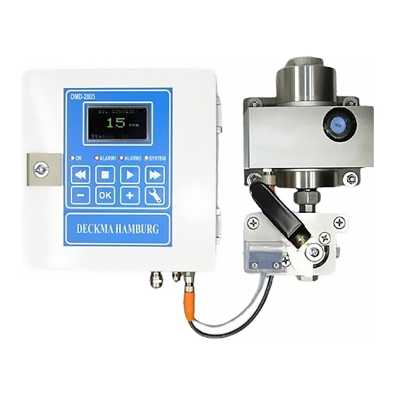
- Page 1 I N S T R U C T I O N M A N U A L 15ppm Bilge Alarm Type OMD-2005 DECKMA HAMBURG GmbH Kieler Straße 316, D-22525 Hamburg - Germany Tel.: +49 (0) 40 54 88 76-0, Fax: +49 (0) 40 54 88 76-10 Internet: www.deckma.com...
- Page 2 The purchaser shall bear the cost and risk of transport of defective parts and repaired parts supplied in replacement of such defective parts. ANY DISMANTLING OR BREAKING OF A SEAL WILL VOID THE WARRANTY Issue: 27.05.08 Instruction Manual OMD-2005 Page 2 of 25...
-
Page 3: Table Of Contents
12.0 Operator Maintenance 12.1 Manual Cell Clean Unit 13.0 Fault Finding 13.1 Memory Card 14.0 Calibration 14.1 Calibration and Repeatability Check 15.0 Spare Parts 15.1 Recommended On Board Spares 16.0 Remarks Issue: 27.05.08 Instruction Manual OMD-2005 Page 3 of 25... -
Page 4: Introduction
DECKMA HAMBURG GmbH INTRODUCTION The OMD-2005 Bilge Alarm Unit has been designed specifically for use in conjunction with 15 ppm oil-water separator units and has a specification and performance which exceeds the requirements of the International Maritime Organization specifications for 15ppm Bilge Alarms contained in Resolution MEPC. -
Page 5: Principle Of Operation
In this mode also the individual adjustment of the time delays for the alarms and the possible changing between 0 - 20 mA or 4 - 20 mA output can be done. Issue: 27.05.08 Instruction Manual OMD-2005 Page 5 of 25... - Page 6 These contacts can be used for external processing of the signal or for control of further functions. If a malfunction or failure of the power supply occurs, all 3 relays will switch to alarm condition. Issue: 27.05.08 Instruction Manual OMD-2005 Page 6 of 25...
-
Page 7: Specification
Roll: Up to 45° Size (over all): 360 mm W x 240 mm H x 100 mm D Degree of Protection: IP 65 Weight: 7,3 kg Pipe Connections: R ¼" Female Issue: 27.05.08 Instruction Manual OMD-2005 Page 7 of 25... -
Page 8: Construction
DECKMA HAMBURG GmbH CONSTRUCTION There are 3 main parts which contained in an OMD-2005: The computer unit is mounted into an epoxy powder painted steel housing to protect the electronics of the display PCB with the data logger and the main board PCB with the terminals for external connections. -
Page 9: Installation
20 s. Mount the OMD-2005 Monitor by means of 6 x M8 screws on to a rigid vertical surface and preferably with the display panel of the monitor at eye level. For service and maintenance sufficient space to all sides should be available. -
Page 10: Piping
PIPING (Refer to Fig. 3) Connect the OMD-2005 Monitor to the sample point of the oily-water separator outlet and to a source of oil free water employing 10 mm OD copper or stainless steel pipe. The sample point should be located on a vertical section of the separator outflow piping to minimize the effects of any entrained air. -
Page 11: Wiring
Do not use the pilot voltage for driving motors, heaters or other high load devices. The pilot voltage is intended for alarm purposes only. Issue: 27.05.08 Instruction Manual OMD-2005 Page 11 of 25... - Page 12 Solenoid Valve 3/2 Way Valve Automatic Stopping Device Air Supply Power Supply Fig. 5 Close front door complete after electrical installation. Water inside the instrument may result in corrosion and malfunction. Issue: 27.05.08 Instruction Manual OMD-2005 Page 12 of 25...
-
Page 13: Typical Control System
Check the wiring of the automatic stopping device and to the alarm system is according the IMO Requirements. c) Check that the grounding has been made according to the relevant regulations. 10.2 Piping a) Check all piping connections for leaks and rectify as appropriate. Issue: 27.05.08 Instruction Manual OMD-2005 Page 13 of 25... -
Page 14: Functional Tests
If this is the case, the cause must be located and rectified. f) If the Zero need to be adjusted, this can be done in the programming mode as described in section 10.4. (Service – Offset) Issue: 27.05.08 Instruction Manual OMD-2005 Page 14 of 25... -
Page 15: Programming Mode
„+“ or „-„ output signal can be modified with “OK”. button. Press the „OK“ button. within the limitations. Select the required point by using the „+“ or „-„ button. Press the „OK“ button. Issue: 27.05.08 Instruction Manual OMD-2005 Page 15 of 25... - Page 16 Press the “Enter” button to >> Fast Forward show details >> and + Very Fast Forward 15 sec Backward - and + 2 min Backward << Fast Backward << and + Very Fast Backward Issue: 27.05.08 Instruction Manual OMD-2005 Page 16 of 25...
-
Page 17: Operating Instructions
10.4 “Service - Offset”. d) Switch the instrument sample supply from the clean water supply to the separator sampling point connection. e) The instrument is now ready for use. Issue: 27.05.08 Instruction Manual OMD-2005 Page 17 of 25... -
Page 18: Operator Notes
The protection cap of the spare unit can be also used as a tool. j) Reconnect the instrument to the separator sampling point. Issue: 27.05.08 Instruction Manual OMD-2005 Page 18 of 25... -
Page 19: Manual Cell Clean Unit
NB: The Manual Cell Clean Unit may also be used during normal operation with sample water, but in this case an alarm occurs because the wiper is passing the light source. Spares: Wiper Seal, Part. No. 30605 Issue: 27.05.08 Instruction Manual OMD-2005 Page 19 of 25... -
Page 20: Fault Finding
13.0 FAULT FINDING See Section 2 for important notes. The OMD-2005 will indicate several malfunctions in the status line of the display. Pressing the “OK” button will lead into an information window, similar to the items listed in the table below. - Page 21 DECKMA HAMBURG GmbH Important Information! Cleaning of Glass Tube at 15 ppm Bilge Alarms OMD-2005 IMPORTANT: NEVER DISASSEMBLE THE UNITS AS THIS MAY VOID THE CALIBRATION AND THE CERTIFICATION! CLEANING HAS ONLY TO BE DONE TROUGH THE REMOVED CELL CAP BY...
-
Page 22: Memory Card
Under normal use the card should not be taken out, as this is linked with the specific system. The card can be read in other OMD-2005 units, but writing is only possible in the related system. -
Page 23: Calibration
A function test for checking the correct installation, can easy be done by changing the position of the 3 way valve. At the clean water position the unit will be in alarm status. Issue: 27.05.08 Instruction Manual OMD-2005 Page 23 of 25... -
Page 24: Spare Parts
2 off Desiccator 65550 1 off Cell Cleaning Brush 30102 1 off O-Ring Set 75775 2 off Fuse T 2 A 40107 Optional item 1 off Manual Cell Clean Unit 75780 Issue: 27.05.08 Instruction Manual OMD-2005 Page 24 of 25... -
Page 25: Remarks
All the modifications and deviations from the standard form, which have to be carried out in the supply, should be attached at this paragraph. Commissioned on: ......by: .......... Date Firm's Name Remarks: Issue: 27.05.08 Instruction Manual OMD-2005 Page 25 of 25...
Need help?
Do you have a question about the OMD-2005 and is the answer not in the manual?
Questions and answers
What is the acceptable time deference between unit OMD 2005 to UTC time?