Table of Contents
Advertisement
Quick Links
Technical documentation
Version history
Version
Date
0.1
16/09/13
0.2
27/09/16
Checked by
Approved by
Tel.: +49 (0)4105 / 65 60 – 0 *
Installation Instructions
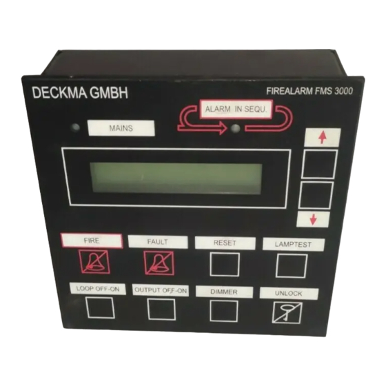
Fire Alarm System FMS3000
Installation Instructions
Author
Checked
JB
TK
TK
STO
ES Elektronik Service; Jan Broockmann
Name – company
Thomas Kruse DECKMA-GMBH
Name – company
DECKMA GmbH
info@deckma-gmbh.de
Email:
201309IA
Note
Produced based on the old operating instructions
Configuration update explained in more detail (page 13)
* Fax: +49 (0)4105 / 65 60 – 25
www.deckma-gmbh.de
* Internet:
Version 0.2
27/09/2016
FMS3000
23/09/2013
Date
23/09/2013
Datum
page 1 of 13
Advertisement
Table of Contents

Related Manuals for Deckma Hamburg FMS3000


Summary of Contents for Deckma Hamburg FMS3000
-
Page 1: Installation Instructions
Technical documentation 201309IA FMS3000 Fire Alarm System FMS3000 Installation Instructions Version history Version Date Author Checked Note 16/09/13 Produced based on the old operating instructions 27/09/16 Configuration update explained in more detail (page 13) Checked by ES Elektronik Service; Jan Broockmann 23/09/2013 Name –... -
Page 2: Table Of Contents
Technical documentation 201309IA FMS3000 Index Cabling requirements ........................3 Fire detectors ..........................5 2.1. Sensor and base ........................5 2.2. Connection of different fire detector types ................5 2.3. Guideline for the installation of sensors and bases or fire detectors ........7 2.4. -
Page 3: Cabling Requirements
The main panel (HT) is constructed as a front panel built-in device. The FMS3000 can either be wall mounted or mounted in a console. When a fire detector detects a fire, then the fire loop module (FM) recognises the event. The main module (BUS Master) cyclically queries the status of all modules. - Page 4 Technical documentation 201309IA FMS3000 VDR(RS-458) (JP2) VDR module shielded twisted pair 2 x 2 x 0.75mm² cable VDR(RS-232) (JP3) VDR module shielded standard serial cable PRINTER (JR1) printer module shielded standard parallel printer cable The recommended cable types are FMGSGO, LMGSGO and MGSGO (Marine) according to VG95218 Part 62.
-
Page 5: Fire Detectors
Technical documentation 201309IA FMS3000 Fire detectors 2.1. Sensor and base Certain fire detectors always consist of a base and a sensor. The conventional sensors SLR-E3, FJ- AE3, DFJ-CE3, DCD-AE3 and DCD-CE3 can all be mounted on the standard base (YBN-R/6). Follow the guideline given below to install and maintain the FMS. - Page 6 Technical documentation 201309IA FMS3000 Tel.: +49 (0)4105 / 65 60 – 0 * DECKMA GmbH * Fax: +49 (0)4105 / 65 60 – 25 info@deckma-gmbh.de www.deckma-gmbh.de Email: * Internet: Version 0.2 27/09/2016 page 6 of 13 Installation Instructions...
-
Page 7: Guideline For The Installation Of Sensors And Bases Or Fire Detectors
Technical documentation 201309IA FMS3000 2.3. Guideline for the installation of sensors and bases or fire detectors Make sure that fire detectors are installed according to the applicable building − regulations and standards. Sensor and base combinations should only be installed where: −... -
Page 8: Commissioning
Technical documentation 201309IA FMS3000 Commissioning The FMS consists of six different modules, which are fixed to a top-hat section rail. More than one example of three modules (main panel (HT), output module and fire loop module (FM)) can be used in an FMS. -
Page 9: Setting The Bus Address
Technical documentation 201309IA FMS3000 Relay 1 3.3. Setting the BUS address The main module (NM01) has a rotary switch on the right side of the housing. The BUS address is to be set to 0 in order that the module is the "BUS Master" in the FMS. -
Page 10: Organisation Of The Software Versions
Technical documentation 201309IA FMS3000 3.6. Organisation of the software versions The modules of the FMS are each operated with the current software version. The log file "FMS3000_Software_ChangeLog.txt" lists the current status of the software (see document: 1.4 FMS_Software_Beschreibung). 3.7. Sequence of on-board commissioning Step 1. -
Page 11: Installation
Technical documentation 201309IA FMS3000 Installation 5.1. Console installation The main panel is installed in the safety console on the bridge and must be well visible. External dimensions: 144 x 144mm installation depth 53mm plus the corresponding D-SUB connector. 5.2. Switch cabinet installation... - Page 12 Technical documentation 201309IA FMS3000 Typical assembly with up to 24 loops Tel.: +49 (0)4105 / 65 60 – 0 * DECKMA GmbH * Fax: +49 (0)4105 / 65 60 – 25 info@deckma-gmbh.de www.deckma-gmbh.de Email: * Internet: Version 0.2 27/09/2016 page 12 of 13...
-
Page 13: Configuration
Technical documentation 201309IA FMS3000 Configuration In order to create the configuration, a pre-prepared Excel file is provided. The modules and their settings are then entered into the file and Excel creates the configuration file on the basis of these entries. The configuration file is copied onto an SD card, which is inserted into the data module.
Need help?
Do you have a question about the FMS3000 and is the answer not in the manual?
Questions and answers