Advertisement
Table of Contents
- 1 Table of Contents
- 2 Control Installation
- 3 Zone Control/Remote Sensor Installation
- 4 Start up
- 5 Connect Wifi
- 6 Account Setup
- 7 Connect System
- 8 Setting up a Non-Zoned System
- 9 Setting up a Zoned System
- 10 Configure Settings
- 11 System Test
- 12 Installation Details
- 13 Frequently Asked Questions
- 14 Specifications
- Download this manual
Advertisement
Table of Contents

Related Manuals for ActronAir QUE QTW-1000


Summary of Contents for ActronAir QUE QTW-1000
- Page 1 Installation and Commissioning Manual...
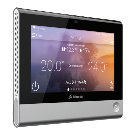
- Page 2 Available in two colours White Black QTW-1000 QTB-1000 Please read this manual carefully and keep it for future reference. For more details, contact ActronAir on 1800 119 229.
-
Page 3: Table Of Contents
Contents Control Installation Zone Control/Remote Sensor Installation Start up - Connect WiFi - Account setup - Connect system - Setting up a non-zoned system - Setting up a zoned system - Configure settings - System test Installation details Frequently Asked Questions Specifications... -
Page 4: Control Installation
Control Installation Location • ENSURE that the wall controller is installed in a location that is within the range of applicable WiFi access point. The distance is dependent on router model and brand. Refer to your unit access point manual. •... - Page 5 Power Supply - 12VDC (Yellow Cat5E spec cables with RJ45 connectors & cable boots) 30m Max (each) PC Board (Indoor Unit) Master Secondary Master Controller Secondary Controller 98.54mm CTR Wall Mounting 43mm 61.44mm 84mm CTR Overall Dimension H x W = 96.7mm x 132.5mm...
- Page 6 Wall Installation Run a yellow RJ45 cable through a 25 mm diameter hole in the wall. Plug in RJ45 cable and secure the controller in the control bracket. Wall controller To indoor board Wall mates (x2) Screw (x2) Control bracket Plyboard wall NOTE: •...
-
Page 7: Zone Control/Remote Sensor Installation
Zone Control / Remote Sensor Installation Dining 24.0 C Zone OFF AC OFF Location • ENSURE that the zone device (zone controller or remote sensor) distance from wall controller (master or secondary) is within the recommended RF range of 30m. •... - Page 8 Power Supply Options (applicable for both zone controller and remote sensor) 12VDC using Cat5E cable (Green Cat5E spec cables with RJ45 connectors & cable boots) (i) Via damper motor option Maximum 20m from the nearest power junction. 1.5V 1.5V 1.5V 1.5V 1.5V 1.5V...
- Page 9 Wall Mount Dimension 43mm 43mm Zone Controller Mount Remote Sensor Mount H x W = 81.1mm x 65.3mm H x W = 51.3mm x 63.3mm Zone Device Combination Options Option Device/s Temperature Averaging Zone Controller Remote Sensor Zone Controller + Remote Sensor Remote Sensor + Remote Sensor Master Controller Master Controller + Remote Sensor...
- Page 10 Wall Installation (applicable for both zone controller or remote sensor) Run a green RJ45 cable through a 25mm diameter hole in the wall. Plug in RJ45 Cable and secure the controller in the control bracket. Zone controller / remote sensor To 12V DC power source Wall mates (x2) Screws (x2)
-
Page 11: Start Up
Start Up (1) Connect WiFi NOTE: This process maybe skipped if WiFi network is not available. This may be completed later by going to ‘ Menu ’ > ‘Settings’ > ‘WiFi Settings’. On master controller, press (hold for 3 seconds then release) MENU button to turn ON the system. -
Page 12: Account Setup
(2) Account Setup Account setup is an optional process. However, getting an account will unlock some of the advanced features offered by the QUE system. These features include mobile connectivity via the QUE Connect App, energy history display and more. To setup an account, from your mobile smart device: enter email address here Download QUE Connect from App Store (iOS) or Google Play... -
Page 13: Connect System
Log-in using the email address and password used in QUE Connect App sign up. When the account is accepted, your A/C system and QUE Connect App are now connected and ready for remote operation once the setup process is complete. Touch ‘Done’ to proceed to next process. - Page 14 On the next screen touch ‘ ’ to start the process. Master controller will start to search for secondary controller. Connect the secondary controller to the WiFi network. Follow the same process as (1) Connect WiFi. NOTE: Make sure that the secondary controller is connected to indoor board terminal (secondary), powered ON and connected to the same SSID point as the master controller.
-
Page 15: Setting Up A Non-Zoned System
The next process will begin the setup of your system and/or connecting zone devices. Touch system or zone set up is required in the system, otherwise touch NOTE: Touching will use the default configuration. As a default, sensor assigned is from master wall controller. Proceed to (4) Account Setup. Setting up a Non-Zoned System After step 8 above, touch ‘Please setup system devices’. -
Page 16: Setting Up A Zoned System
(iii) If additional devices are required to average a reading, touch ‘Add a system device’ then follow the on-screen instructions. You can add a remote sensor, a master controller or secondary Assigned to remote sensor controller (if available). NOTE: When pairing a remote sensor, record the serial number shown on the back of the device and ensure that the same number appears on the master controller screen during the setup. - Page 17 Option 1 : Zone will use the zone controller Touch ‘A new zone controller’. (ii) Follow the on screen instructions. (iii) On the right side of the zone controller, press and hold the pair button for three seconds. Green blinking light means pairing is successful. Pair button VX.XX (press here)
- Page 18 (iv) The next screen will show that the Zone Controller is now paired to the zone. It will also show the serial number of the connected device. Make sure this is the same serial number of the actual connected device (check the back of the device for serial number). Touch ‘<Back’.
- Page 19 (ii) On the right side of the remote sensor, press and hold the pair button for three seconds. • Green blinking light means pairing is successful. Pair button (press here) • Red blinking light means pairing has failed. Repeat this step until pairing is successful. (iv) The next screen will show that the Remote Sensor is now paired to the zone.
- Page 20 Option 3: Zone will use both remote sensor and zone controller to average temperature reading. Follow the steps of Option 3 to use remote sensor. Then on screen, touch ‘add a zone device’. (ii) Touch ‘zone controller’. Then follow the same process as using zone controller in Option 2.
- Page 21 Option 5: Zone will use master control Touch ‘Master Controller (this controller)’. NOTE: If there is a secondary controller used on the system, it is possible to use it instead of master controller. (ii) Next screen will show if the master controller is linked. Touch (iii) Next screen will show that the ‘Master Controller’...
-
Page 22: Configure Settings
(4) Configure Settings Touch the fourth circle, ‘Configure Settings’. NOTE: This may be completed later by going to ‘ Menu’ then select ‘Settings’ then ‘Date and time’. By default, the date is set to ‘Auto set’. It will follow the internet router time settings. -
Page 23: System Test
(5) System Test Touch the fifth circle, ‘System Test’. Touch to start system test. Touch ‘Test 1: Zone detection’ Touch ‘Start’ and wait until the system finish zone test. When finished, display will show the number of zones connected to the system. a) Shows test result for zoned system b) Shows test result for non-zoned system. - Page 24 Touch ‘Indoor fan test’. Touch ‘Start’ to begin fan test. Go to the nearest air outlet and observe if there is air coming out. If yes, touch and proceed to step 9. Otherwise, touch then check the indoor fan is wired correctly. Repeat step 6-8 to run fan test again.
- Page 25 Select the zones that will be included in self learn mode. Touch ‘Ok’. System will start self learn mode. Fan will randomly stop and run until it finishes Stage 3 test. Touch ‘Finish’ when the option appears. Next step will start Run system to check if the system is cooling and heating.
- Page 26 System will start 3 minutes countdown before it will begin heating test. Screen will show the system in heating. Wait for the compressor speed to reach more than 50%. Go to nearest air outlet and observe if the air is warm. If yes, touch Start Cancel Finish...
-
Page 27: Installation Details
Installation Details Installer MUST complete their contact details on the wall controller via Menu > Settings > Edit servicing contact details. Complete the information below for future reference. Zoned System? System Name: Controller Serial Number Master Wall Controller Secondary Wall Controller (if applicable) Zone Number Zone Name... -
Page 28: Frequently Asked Questions
Frequently Asked Questions (FAQ) 1. Q: Do I need a WiFi signal or internet connection to install the QUE system? A. No. You can install and use a QUE system without a WiFi signal or internet connection. Because the zone devices use inbuilt RF signal to communicate with the Master Controller, they can operate without an internet connection. - Page 29 6. Q: Can I connect the Master and Secondary Controllers to power source other than the indoor board? A. No, both the Master & Secondary Controllers must be connected to the indoor board, where they are both allocated a dedicated terminal. 7.
-
Page 30: Specifications
Specifications Electrical Sensors Power supply 12VDC ±5% Temperature Sensor ± 0.5 C accuracy Cable specification ActronAir Cable Humidity Sensor ± 5% accuracy Cable length 30m max Proximity/Light Sensor 10 cm range detection Screen Display Speaker Type LCD capacitive touch screen... - Page 31 Notes...
- Page 32 Copyright © 2017 All rights reserve. No part or contents of this book maybe reproduced or transmitted in any form or by any means without the written permission of Actron Engineering Pty. Ltd. 9590-6001 v8...
Need help?
Do you have a question about the QUE QTW-1000 and is the answer not in the manual?
Questions and answers