Table of Contents
Advertisement
Advertisement
Chapters
Table of Contents

Related Manuals for ETAS ES930.1

Summary of Contents for ETAS ES930.1
- Page 1 ETAS ES930.1 Multi-I/O Module User Guide...
- Page 2 The data in this document may not be altered or amended without special noti- fication from ETAS GmbH. ETAS GmbH undertakes no further obligation in relation to this document. The software described in it can only be used if the customer is in possession of a general license agreement or single license.
-
Page 3: Table Of Contents
Overview ............29 4.1.2 Cold-junction Compensation with A/D Converter ....29 ES930.1 - User Guide... - Page 4 Behavior for Rapid Prototyping Applications ....... . 50 ES930.1 - User Guide...
- Page 5 Protection of the Assembly ..........65 ES930.1 - User Guide...
- Page 6 Cabling of the ES930.1 for MC Applications ......71 11.3.2 Cabling of ES930.1 for RP Applications......72 11.3.3 Daisy Chain Connections ("IN", "OUT") .
- Page 7 ES930.1 ........
-
Page 8: About This Document
The target to be achieved is defined in the heading. The necessary steps for his are in a step-by-step guide: Target definition 1. Step 1 2. Step 2 3. Step 3 > Result Presentation of Supporting Information NOTE Contains additional supporting information. ES930.1 - User Guide... -
Page 9: Basic Safety Notices
Intended Use ..........9 General Safety Information Please observe the Product Safety Notices ("ETAS Safety Notice") and the fol- lowing safety notices to avoid health issues or damage to the device. - Page 10 • Route the power cable in such a way that it is protected against abrasion, damages, deformation and kinking. Do not place any objects on the power cable! ES930.1 - User Guide...
- Page 11 • Adhere to the maximum permissible cable lengths! • Do not use any damaged cables! Cables may be repaired only by ETAS! • Never apply force to insert a plug into a socket. Ensure that there is no contamination in and on the connection, that the plug fits the socket, and that you correctly aligned the plugs with the connection.
- Page 12 Do not transport the modules at the cable of the module or any other cables. Maintenance The product is maintenance-free. Repair If an ETAS hardware product should require a repair, return the product to ETAS. Cleaning the module housing • Use a dry or lightly moistened, soft, lint-free cloth for cleaning the module housing.
- Page 13 Install the modules only at locations with the same electrical potential or iso- late the modules from the installation location. Cabling For detailed information about cabling, see the User Guide of the module. ES930.1 - User Guide...
-
Page 14: Hardware Description
3.1.1 Input and Output Channels Overall, the ES930.1 module features 4 thermo, 8 analog and 4 digital inputs. 4 analog and 6 digital outputs are available as output channels, 4 sensor supplies and 6 half-bridge switches with current measurement as power stages. Since the power stages are integrated in the ES930.1 module, the external signal con-... -
Page 15: Configuration And Data Acquisition
3.1.4 Configuration and Data Acquisition All configurations of the ES930.1 module can be defined for each channel in each case. The sampling of the signal at the inputs and the output of signals are done... -
Page 16: Simple Cabling Concept Of Inputs And Outputs
INTECRIO or ASCET-RP • Standalone operation with ES93x configuration tool • Updating the firmware of the module with HSP The complete technical data of the ES930.1 can be found in chapter 13 on page 85. ES930.1 - User Guide... -
Page 17: Module
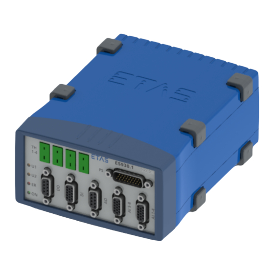
Module 3.3.1 Housing The ES930.1 uses a housing with connections on the front and the rear side of the device. The robust metal housing of the ES930.1 is equipped with non-slip plastic feet. The module is designed for the accommodation in the vehicle or lab. In order to stabilize it, it can easily be screwed onto a support system. - Page 18 3.3.2.2 LEDs The front side of the ES930.1 module features four LEDs. The LEDs U1 and U2 can be configured by the user in the application software, the LEDs ER and ON indicate the following operating states of the module:...
-
Page 19: Rear Side
ETAS Hardware Description 3.3.3 Rear Side Fig. 3-3 Rear Side The rear side of the ES930.1 module features the following connections (see Fig. 3-3 on page 19): Name Connection Meaning Daisy chain In Input; Ethernet connection to the previous module... -
Page 20: Overview Of Function Groups
SERVICE Fig. 3-4 ES930.1 Block Diagram The block diagram in Fig. 3-4 on page 20 displays function groups of the ES930.1 module that are described in the following chapters: • Power supply (see chapter 3.5 on page 21) • ETAS daisy chain connections "IN" and "OUT" (see chapter ) •... -
Page 21: Power Supply
3.5.3 Power Supply of a Single Module The ES930.1 module uses a daisy chain topology for cabling with the PC and additional modules. The Ethernet data line and the power supply are looped through the daisy chain connections of the module: •... -
Page 22: Switching The Module On And Off
3.5.5 Switching the Module on and off The ES930.1 module is not equipped with the "Wake Up" function to ensure a controllable behavior of the outputs, including the Half-bridges (power stages) and circuits and devices connected to it, when switching the module on and off. -
Page 23: Data Transfer
Hardware Description Data Transfer The ES930.1 as well as the ES4xx and ES63x modules use a 100-Mbit/s Ether- net network connection in duplex mode for the data transfer. The data transfer can very flexibly be adapted to the measuring setup and the measuring task. - Page 24 With a real- time capable master, such as a rapid prototyping system, access to many dif- ferent types of I/O signals is possible at extremely short cycle times. ES930.1 - User Guide...
-
Page 25: Signal Acquisition And Signal Output
Example: Flow sensor, axle speed is not proportional to flow rate The measured signals and their adaptation allows a representation of the phys- ical, technical and derived variables as well as the measure variables in the desired physical unit. ES930.1 - User Guide... -
Page 26: Requests
(active-inactive edge, inactive-active edge, both edges or the end of a cycle). If an event occurs, the signals at all inputs of the ES930.1 are captured. 3.7.2.2 Behavior in Case of Oversampling by the Application Program In case of oversampling, a signal with a higher sampling rate than it is actually required for the transfer of the signal bandwidth is captured. -
Page 27: Signal Output
Signal Output 3.7.3.1 Transfer of the Configuration Value The output or change of signals at an output channel of the ES930.1 is trig- gered by a configuration value that is transferred with a STIM packet. 3.7.3.2 Response Time and Update Rate For MC applications, the response time or update rate of the ES930.1 for the... -
Page 28: Overload For Rapid Prototyping Applications
ES910 can no longer process the data of the ES930.1. The ES910 discards data of the ES930.1 or data of other ETAS daisy chain modules that are present at its I/O port. The I/O port of the ES910 to which the ES930.1 is connected is overloaded. -
Page 29: Thermo Channels ("Th1-4" Connections)
ETAS Thermo Channels ("TH1-4" Connections) Thermo Channels ("TH1-4" Connections) The ES930.1 is equipped with four mini-TC sockets ("TH1" to "TH4") for the con- nection of thermocouples of type K. Assemblies of the Thermo Channels 4.1.1 Overview Thermo Channel n Open TC... -
Page 30: Open Tc Detection
The thermo channels are electrically isolated from each other. Each thermo channel is electrically isolated from the supply voltage and from the housing of the module. Hence, the use of non-isolated thermocouples in non-floating installations is also possible without a restriction on accuracy. ES930.1 - User Guide... -
Page 31: Digital Input Channels ("Di" Connection)
Fig. 5-1 Digital Input Channels The digital input channels "DI 1" to "DI 4" of the ES930.1 feature an identical design and consist of an input stage with signal acquisition and signal process- ing. The input stage of each channel (see in Fig. 5-1 on page 31) consists of the following assemblies : •... -
Page 32: Schmitt Trigger
If the signal changes do not occur, no new timer measured values can be deter- mined. If the timeout of the ES930.1 expired, the values measured last of the counters, the active and the inactive time are retained without changes. They are transferred to the application program during the next sampling. -
Page 33: Counter Overflow Detection
The digital input channels "DI 1" to "DI 4" are not electrically isolated against each other. The digital input channels are electrically isolated together as chan- nel group to the supply voltage and as channel group to the housing of the module. ES930.1 - User Guide... -
Page 34: Measuring Functions
5.2.1 Definitions of the measuring Signals This section defines signals that are used for the description of the measuring functions of the digital inputs of the ES930.1. 5.2.1.1 Legend Tab. 5-1 on page 34 summarizes the symbols used in the figures of the chapter on "Measuring Functions". -
Page 35: Fig. 5-4 Active And Inactive Pulse
A cycle describes an integer multiple of a period: Cycle = n * period A cycle can start with: • an inactive-active edge • an active-inactive edge Input Cycle Signal Active Inactive Time Fig. 5-6 Cycle, starting with an inactive-active Edge and n=3 ES930.1 - User Guide... -
Page 36: Overview Of Measuring Functions
Cycle, starting with an active-inactive Edge and n=3 5.2.2 Overview of measuring Functions The ES930.1 module can capture digital signals at the four input channels "DI 1" to "DI 4" and analyze them with the help of the following measuring func- tions:... -
Page 37: Measurement Of The Signal State (State)
Measurement of active and inactive State (fixed measure Rate) In the application software, it can be defined at which input channels of the ES930.1 the state should be measured. NOTE The state of a non-selected input channel is set to the value 0. -
Page 38: Counter
The signal at the measuring channel is counted independent of signals at other measuring channels. The counter assigned to the measuring channel is config- ured as an up-counter. The ES930.1 can count edges with the following measuring procedures according to the configuration in the application software: •... -
Page 39: Fig. 5-9 Counting Of Inactive-Active Edges
In the example in Fig. 5-11, the counter is reset at every sampling point. Counting of Cycles Input Cycle Cycle Signal Active Inactive Time Fig. 5-12 Counting of Cycles The counter is reset at every sampling point. ES930.1 - User Guide... -
Page 40: Time Measurement
Time Measurement Measuring Procedure In the time measurement, the ES930.1 always acquires the active time and the inactive time of the signal at the measuring channel. With these measured val- ues, the signals can be determined completely in different periods. -
Page 41: Fig. 5-13 Measurement Of Active Time During The Last Period
Act ive Time Fig. 5-16 Measurement of active Time until the last current sampling Point The sum of the active time can be determined over the entire measure time without any gaps (see Fig. 5-16 on page 41). ES930.1 - User Guide... -
Page 42: Calculation Of Cycle Duration, Frequency And Scan Ratio
5.2.6 Calculation of Cycle Duration, Frequency and Scan Ratio In the time measurement operating mode, the ES930.1 acquires the active and inactive time of a period or a cycle of the signal at the measuring channel. The measured times are the basis for calculating the cycle duration, frequency and scan ratio. -
Page 43: Calculation Of The Speed
Fig. 5-17 16-2 "Speed Sensor Wheel" To be able to determine a speed from periodic signal forms using the ES930.1, a cycle can be defined in the configuration software, e.g.: 1 revolution = 1 cycle = (16-2) periods = 14 periods... -
Page 44: Fig. 5-18 Principle Of The Input Signal Of A "Speed Sensor Wheel
The measurement result depends on the start of the cycle. This process allows determining the average speed using periodic input sig- nals: --------------------------------------------------------------- - [rpm] Speed active time inactive time ES930.1 - User Guide... -
Page 45: Analog Input Channels ("Ai 1-4"/"Ai 5-8" Connections)
Fig. 6-1 Analog input Channels "AI 1" to "AI 4" The eight analog input channels "AI 1-4" and "AI 5-8" of the ES930.1 are identical in design. Each channel consists of the following assemblies (see block dia- gram in Fig. 6-1 on page 45): •... -
Page 46: A/D Converter
6.2.5.2 Recommendations for the Configuration of the digital Filter The -3-dB limit frequency of the digital filter system of the ES930.1 can be con- figured in the application program. To avoid aliasing effects, recommendations for the configuration of the filter should be observed depending on the selected INCA sampling rate. -
Page 47: Compensation Of Group Runtime
The group runtime is the time required by the Input signal of an analog or digital filter to pass through the filter. One property of the ES930.1 is the in-module compensation of the group run- time. For this purpose, the group runtimes of the analog anti-aliasing filter and the configurable digital filter are taken into account. -
Page 48: Example
) = 60 V - 40 V = 20 V CMyz Electrical Isolation The analog input channels are electrically isolated from each other. Each ana- log input channel is electrically isolated from the supply voltage and from the housing of the module. ES930.1 - User Guide... -
Page 49: Outputs To The Sensor Power Supply
ETAS Outputs to the Sensor Power Supply Outputs to the Sensor Power Supply The ES930.1 is equipped with four outputs for the power supply of sensors that are available at the connections "AI 1-4" and "AI 5-8". Channel Groups The two sensor supply voltage channels at the "AI 1-4" connection and the two sensor supply voltage channels at the "AI 5-8"... -
Page 50: Overcurrent Protection
RP model when switching on the module. If the sensor supply voltage channels are not configured as described above, the already existing sensor voltage is briefly interrupted at the start of the RP model on the ES910. ES930.1 - User Guide... -
Page 51: Fig. 8-1 Analog Output Channels
Protection Converter Fig. 8-1 Analog Output Channels The analog output channels "AO 1" to "AO 4" of the ES930.1 feature an identical design. Each channel consists of the following assemblies (see block diagram in Fig. 8-1 on page 51): •... - Page 52 The analog output channels "AO 1" to "AO 4" are not electrically isolated against each other. The analog output channels are electrically isolated together as channel group to the supply voltage and as channel group to the housing of the module. ES930.1 - User Guide...
-
Page 53: Fig. 9-1 Block Diagram Of A Digital Output Channel
Fig. 9-1 Block Diagram of a digital Output Channel The digital output channels "DO 1" to "DO 6" of the ES930.1 feature an identical design. Each channel consists of the following assemblies (see block diagram in Fig. 9-1 on page 53): •... - Page 54 "external" con- trol, but which are to short for further assemblies of the ES930.1 module or which cannot be processed error-free. For this reason, the output signal of the counter unit is monitored with the Min Pulse assembly and, if necessary, lim- ited to a minimum pulse width.
- Page 55 The digital output channels "DO 1" to "DO 6" are not electrically isolated against each other. The digital output channels are electrically isolated together as channel group to the supply voltage and as channel group to the housing of the module. ES930.1 - User Guide...
-
Page 56: Fig. 9-2 Simplified Diagram Of The Output Channel Characteristics
Digital Output Channels – Rise and Fall Time An additional capacitive load on an output channel increases the rise and fall times. For this reason, it is recommended that you use cables with a maximum length of 4 m. ES930.1 - User Guide... - Page 57 Active time Duty cycle ----------------------------------------------------------------- - Active time Inactive time Active time Worst-case duty cycle ----------------------------------------------------------------- - Active time Inactive time For this purpose, the absolute maximum deviation can be set to = 200 ns. ES930.1 - User Guide...
-
Page 58: Fig. 9-3 "Digital Output" Functionality
Pulses can be generated with defined value for the active time. Output Request Signal Active Inactive Time Fig. 9-5 "Pulse Out" Functionality An additional request, which arrives during the processing of the first request, is discarded. ES930.1 - User Guide... -
Page 59: Fig
10.1 Half-bridges (Power Stages) and Half-bridge Channel Groups (Power Stage Groups) The six Half-bridges (power stages) "PS 1" to "PS 6" of the ES930.1 are com- bined into three identical channel groups (power stage groups): • Channel group 1: Half-bridges "PS 1" and "PS 2"... - Page 60 The power MOSFETs are alternately occupying one of the following switching states: • High-side switch "On" and low-side switch "Off" • High-side switch "Off" and low-side switch "On" The half-bridge switches cannot be used individually, only together as Half- bridge. ES930.1 - User Guide...
-
Page 61: Fig. 10-2 Current Measurement Channel
Half-bridge. 10.3.4.2 Anti-aliasing Filter The anti-aliasing filter is a 1st order analog low-pass with a limit frequency of 15 kHz. The filter can be neither configured nor bridged. ES930.1 - User Guide... - Page 62 The IIR filter (Infinitive Impulse Response filter) is a 2nd order Bessel filter for which the user is automatically provided a matching selection of limit frequen- cies (0.4 Hz to 4 kHz) for the configuration depending on the sampling rate. ES930.1 - User Guide...
- Page 63 "Enable PS n/n+1" signals enables a safe starting and shutting down of the system during the Init and Exit tasks by the RP model according to the user definition. ES930.1 - User Guide...
- Page 64 Full-bridges in the described groups. Two digital output channels are required for the control of a Full-bridge. The corresponding digital output channels must be configured so that a synchro- nous control of the two interconnected Half-bridges is ensured. ES930.1 - User Guide...
-
Page 65: Protection Of The Half-Bridges
Please return defective modules to ETAS. Notes about the procedure are available from the local ETAS sales and service locations. The contact information is located in the chapter 16 on page 133. -
Page 66: Startup
11.1.2 Fastening the Module onto a Carrier System The ES930.1 has a robust metal housing equipped with non-slip plastic feet. The module can easily be screwed onto a support system for fastening in the vehicle or lab. The screw threads for fastening the module are already in the housing and easily accessible. -
Page 67: Connecting Several Modules Mechanically
11.1.3 Connecting several Modules mechanically Because of the use of ETAS system enclosures, the ES930.1 can also be com- bined with modules of the ETAS compact series (ES59x, ES6xx, ES910). They can simply be combined into larger blocks by using the supplied T-connectors. -
Page 68: Fig. 11-3 Connecting The Es930.1 With Another Module
ETAS Startup Fig. 11-3 Connecting the ES930.1 with another Module 6. Turn the fasteners of the T-connector by one-quarter turn. This locks the connection of the two modules. 7. Click the two additional T-connectors into the installation openings on the opposite longitudinal side of the device 8. -
Page 69: Applications
ES93x module chain for measurement and calibration with INCA. The ETAS daisy chain concept enables a simple network architecture, since only the ES930.1 or the first module of the module chain must be connected with the "OUT" connection of the ES930.1. Additional bus analysis functions on the buses CAN, LIN and FlexRay as well as (X)ETK bypass applications with measuring and calibrating can be made accessible with ES59x modules. -
Page 70: Cabling
Startup The ETAS daisy chain concept enables a simple network architecture since only the ES930.1 or the first module of the module chain must be connected with the "IO" connection of the ES910. If the ES910 is used, it is possible to access the connected modules whose signals can be processed directly in the rapid prototyping model from within the rapid prototyping model. -
Page 71: Cabling Of The Es930.1 For Mc Applications
ETAS Startup 11.3.1 Cabling of the ES930.1 for MC Applications Fig. 11-6 Cabling of the ES930.1 with ETAS Modules (MC Application) Cables Function Short name Fig. 11-6 Power supply cable CBP120, CBP1205 PC or ES51x Ethernet cable CBE100 CAN/ LIN/ FlexRay connection cable... -
Page 72: Cabling Of Es930.1 For Rp Applications
ETAS Startup 11.3.2 Cabling of ES930.1 for RP Applications Fig. 11-7 Cabling of ES930.1 with ETAS Modules (RP Application) Cables Function Short name Fig. 11-7 PC connection cable CBE200 Power supply cable CBP120, CBP1205 CAN/ LIN/ FlexRay connection cable CBCFI100... -
Page 73: Daisy Chain Connections ("In", "Out")
Daisy Chain Connections ("IN", "OUT") 11.3.3.1 Connection with the PC For the connection of the PC with the ES930.1 module ("IN" connection), you need a combined Ethernet and power supply cable (CBEP410, CBEP4105, CBEP415 or CBEP4155). Cabling the ES930.1 with the PC and the power supply 1. -
Page 74: Inputs (Connections "Di", "Ai 1-4" And "Ai 5-8")
Inputs (Connections "DI", "AI 1-4" and "AI 5-8") For the connection of the inputs "DI", "AI 1-4" and "AI 5-8" of the module, three CBAV420.1 cables are required. Cabling the inputs of the ES930.1 1. Connect a CBAV420.1 cable with the "DI" connection of the ES930.1. -
Page 75: Handling Of Problems
Handling of Problems Handling of Problems This chapter provides information about the steps to be taken in case of prob- lems with the ES930.1 and general problems that are not specific to a single hardware or software product. 12.1 LED Displays To assess the operating state and for fault removal of the ES930.1, please... -
Page 76: Problems With The Es930.1
Check whether the func- does not find any ETAS ES930.1 flashing red and tion for automatically daisy chain modules. are the LEDs of the ETAS switching to the power- daisy chain modules save mode is enabled on flashing green? your PC card . - Page 77 PC is correct and functional. Check whether the mod- ules in the module chain are correctly connected. You are using the ETAS Check whether you daisy chain configura- changed the position of tion tool and the module one or several modules does not furnish any in the chain.
- Page 78 Use only PCM- CIA cards with 32-bit data bus, mini-PCI or ExpressCards. Are you operating the Install a current driver for ES930.1 on a PC with the network card that multi-core processor? supports the NDIS proto- col. The LED lights red.
-
Page 79: Problems And Solutions
Windows 7, 8.1 and 10 systems. Network security policies, however, may request the APIPA mechanism to be disabled. In this case, you cannot use a network adapter which is configured for DHCP to access ETAS hardware. The ETAS Network Manager displays a warning message. -
Page 80: Search For Ethernet Hardware Fails
Whenever you switch from a DHCP company LAN to the ETAS hardware net- work, it takes at least 60 seconds until ETAS hardware can be found. This is caused by the operating system’s switching from the DHCP protocol to APIPA, which is being used by the ETAS hardware. - Page 81 Cause: Automatic disruption of network connection It is possible after a certain period of time without data traffic that the network card automatically interrupts the Ethernet connection. This can be prevented by setting the registry key autodisconnect. ES930.1 - User Guide...
-
Page 82: Personal Firewall Blocks Communication
Ethernet hardware at all, although the configuration parameters are correct. Some actions in ETAS products can lead to problems if the firewall is not prop- erly parameterized, e.g. when opening the experiment environment in ASCET or for the hardware search by INCA or HSP. - Page 83 ETAS Handling of Problems • Outgoing TCP/IP connections to the network configured for the ETAS application, destination ports 18001 to 18020 NOTE The ports to be used in a specific case depend on the hardware used. For more detailed information about the port numbers to be used, see the respective hardware documentation.
- Page 84 *.ini files are modified during the work. The ETAS software must be installed by an administrator in any case. It is rec- ommended that the administrator ensures that the ETAS product or the pro- cesses are added to the list of selected exceptions of the Windows Firewall after the installation.
-
Page 85: Technical Data
Electrical Data ..........92 13.1 Labels on the Product 13.1.1 Product Label Fig. 13-1 Product Label ES930.1 - User Guide... -
Page 86: Used Symbols
Marking for KCC conformity, see chapter 13.3.2.3 on page 88 Labeling for WEEE, see chapter 13.5 on page 88 13.1.3 Labeling of the Connections Symbol Description Labeling of the daisy chain port„IN“ (input) Labeling of the daisy chain port„OUT“ (output) ES930.1 - User Guide... -
Page 87: Standards And Norms
CE Conformity 13.3.2.1 European Union (EU) With the CE mark attached to the product or its packaging, ETAS confirms that the product corresponds to the product-specific, applicable directives of the European Union. The CE Declaration of Conformity for the product is available upon request. -
Page 88: Declarable Substances
Technical Data 13.3.2.2 UKCA Conformity (Great Britain) With the UKCA mark attached to the product or its packaging, ETAS confirms that the product corresponds to the product-specific, applicable standards and directives of Great Britain. The UKCA declaration of conformity for the product is available on request. -
Page 89: Use Of Open Source Software
13.7.1 Maintenance the Product Do not open or change the module! Works on the module housing may be exe- cuted only by qualified technical personnel. Send defect modules to ETAS. 13.7.2 Cleaning the Product We recommend to clean the product with a dry cloth. -
Page 90: System Requirements
13.8.2 Hardware Operating the ES930.1 module requires a DC voltage supply of 7 V to 29 V and operating the Half-bridges (power stages) of the ES930.1 requires a DC voltage supply of 7 V to 32 V. -
Page 91: Software
13.8.2.3 ETAS Hardware (Rapid Prototyping) ES910.2, ES910.3 13.8.3 Software The following software in the following versions (and higher) is required for configuring the ES930.1 as well as for control and data acquisition: 13.8.3.1 General • ES93x Configuration Tool V1.3.0 •... -
Page 92: Electrical Data
ETAS Technical Data 13.9 Electrical Data NOTE Unless described otherwise, the electrical data of the ES930.1 were mea- sured directly at the contacts of the module. 13.9.1 Power Supply Operating voltage Operating voltage for the module at "IN" connection: 7 V to 29 V DC Separate operating voltage for the Half-bridges at "PS"... - Page 93 Input-to-ground of voltage supply: 60 V DC / 30 V AC Input-to-housing: 60 V DC / 30 V AC Electrical isolation Input-to-input, input-to-supply voltage, input-to-housing Reference temperature T for T is 25 °C (corresponds to 298.15 K) ES930.1 - User Guide...
- Page 94 Events 4 event sources per module can be configured differently Events for triggering a synchronous data acquisition on the ES930.1 mod- Events for triggering the model trigger in the ES910 prototyping module ES930.1 - User Guide...
- Page 95 ±60 V DC, all measuring ranges Input-to-input: 60 V DC / 30 V AC Input-to-ground of voltage supply: 60 V DC / 30 V AC Input-to-housing: 60 V DC / 30 V AC Electrical isolation Input-to-input, input-to-supply voltage, input-to-housing ES930.1 - User Guide...
- Page 96 Event NOTE The software configurable filter of a measuring channel (analog inputs [AI] and current measurement channels [PS] of the Power Stages) is automati- cally deactivated when the measurement channel is operated in the event mode. ES930.1 - User Guide...
- Page 97 2 channels at "AI 1-4" connection and 2 channels at "AI 5-8" connection Assignment of channels Assignment to sensors or input chan- nels of the ES930.1 can be randomly configured Output voltage Configurable per channel: predefined values ("Off", +5 V, +8 V,...
- Page 98 ±45 V DC Output-to-ground of voltage supply: 60 V DC / 30 V AC Output-to-housing: 60 V DC / 30 V AC Electrical isolation All 4 outputs together as channel group to supply voltage and to hous- ES930.1 - User Guide...
- Page 99 60 V DC / 30 V AC Electrical isolation All 6 outputs together as channel group to supply voltage and to hous- Functions Digital Out, Pulse Out, PWM Out and simultaneously activation of power stages "PS"; synchronous channel groups can be configured ES930.1 - User Guide...
- Page 100 For the Half-bridges, the driver ICs Infineon TLE7182EM are used. data sheet "TLE7182EM H-Bridge and Dual Half-bridge Driver IC (Data Sheet, Rev 1.1, Sept. 2010)" with detailed information is available on the Infineon Internet page. ES930.1 - User Guide...
- Page 101 4 kHz) NOTE The software configurable filter of a measuring channel (analog inputs [AI] and current measurement channels [PS] of the Power Stages) is automati- cally deactivated when the measurement channel is operated in the event mode. ES930.1 - User Guide...
- Page 102 CAUTION Users who want to fit their own cables for the "DO" connection must observe the notes about the design of the CBAV421.1 cable offered by ETAS to avoid damage to the module (see chapter 14.2.2 on page 116). ES930.1 - User Guide...
- Page 103 CAUTION Users who want to fit their own cables for the "DI" connection, must observe the notes about the design of the CBAV420.1 cable offered by ETAS to avoid damage to the module (see chapter 14.2.1 on page 112). CAUTION...
- Page 104 CAUTION Users who want to fit their own cables for the "AO" connection, must observe the notes about the design of the CBAV421.1 cable offered by ETAS to avoid damage to the module (see chapter 14.2.2 on page 116). ES930.1 - User Guide...
- Page 105 CAUTION Users who want to fit their own cables for the "AI 5-8" connection, must observe the notes about the design of the CBAV420.1 cable offered by ETAS to avoid damage to the module (see chapter 14.2.1 on page 112).
- Page 106 CAUTION Users who want to fit their own cables for the "AI 1-4" connection, must observe the notes about the design of the CBAV420.1 cable offered by ETAS to avoid damage to the module (see chapter 14.2.1 on page 112).
- Page 107 CAUTION Users who want to fit their own cables for the "DO" connection, must observe the notes about the design of the CBAV422.1 cable offered by ETAS to avoid damage to the module (see chapter 14.2.3 on page 118). ES930.1 - User Guide...
-
Page 108: Fig. 14-7 "Th1-4" Connection
ETAS Pin Assignment and Accessories 14.1.7 "TH1-4" Connection Fig. 14-7 "TH1-4" Connection ES930.1 "TH1-4" connection Meaning Signal Input (+) Input (-) Mini-TC sockets are installed at the "TH1-4" connections. ES930.1 - User Guide... - Page 109 Ground Ground Receive data, minus Send data, minus Receive data, plus Ground Ground UBatt Operating voltage Send data, plus A LEMO 1B 8-pin connector with L-coding (connection identified in green) is installed at the "IN" connection. ES930.1 - User Guide...
- Page 110 UBatt Operating voltage Ground Ground Receive data, plus Send data, minus Receive data, minus Ground Ground Send data, plus A LEMO 1B 8-pin socket with A-coding (connection identified in yellow) is installed at the "OUT" connection. ES930.1 - User Guide...
-
Page 111: Fig. 14-10 Cable For Inputs And Outputs
CBAV421.1 cables and one CBAV422.1 cable are required. The open connections of the cables CBAV420.1, CBAV421.1 and CBAV422.1 can be fitted individually by the user, so that it can be adapted to the specific plug connector system of the measuring setup. ES930.1 - User Guide... -
Page 112: Fig. 14-11 Cbav420.1 Cable With Wiring Plan
CAUTION To avoid in such measurement setups fault currents within the module ES930.1 between the ground terminals of the connector "DI", we recommend to connect the ground connections DI_CH1_GND to DI_CH4_GND either at the open end of the CBAV240.1 cable or directly in the connector of a self- assembled cable. -
Page 113: Di_Ch1
Open cable end Pair Color AI_CH8 white AI_CH8_GND brown AI_CH7 green AI_CH7_GND yellow AI_CH6 gray AI_CH6_GND pink AI_CH5 blue AI_CH5_GND SensorSupply_CH4_GND 5 black SensorSupply_CH4 violet SensorSupply_CH3_GND 6 gray/pink SensorSupply_CH3 red/blue 5, 10, 15 N.C. Housing Shield ES930.1 - User Guide... - Page 114 Open cable end Pair Color AI_CH4 white AI_CH4_GND brown AI_CH3 green AI_CH3_GND yellow AI_CH2 gray AI_CH2_GND pink AI_CH1 blue AI_CH1_GND SensorSupply_CH2_GND 5 black SensorSupply_CH2 violet SensorSupply_CH1_GND 6 gray/pink SensorSupply_CH1 red/blue 5, 10, 15 N.C. Housing Shield ES930.1 - User Guide...
- Page 115 14.2.1.5 Overview: Assignment of the CBAV420.1 Cable for use at the Connections "DI", "AI 5-8" and "AI 1-4" "DI" / "AI "DI" connection "AI 5-8" connection "AI 1-4" connection CBAV420.1: 1-4" / "AI Open cable end 5-8" Signal Signal Signal Pair Color DI_CH4...
-
Page 116: Fig. 14-12 Cbav421.1 Cable With Wiring Plan
Assignment of the CBAV421.1 Cable when used at "DO" Connec- tion SUBD Signal Open cable end Pair Color DO_CH5 White DO_GND Brown DO_CH4 Green DO_GND Yellow DO_CH3 Gray DO_GND Pink DO_CH2 Blue DO_GND DO_CH6 Black DO_GND Violet DO_CH1 Gray/pink DO_GND Red/blue Housing Shield ES930.1 - User Guide... - Page 117 DO_CH5 N.C. White DO_GND AO_GND Brown DO_CH4 AO_CH4 Green DO_GND AO_GND Yellow DO_CH3 AO_CH3 Gray DO_GND AO_GND Pink DO_CH2 AO_CH2 Blue DO_GND AO_GND DO_CH6 N.C. Black DO_GND N.C. Violet DO_CH1 AO_CH1 Gray/pink DO_GND AO_GND Red/blue Housing ES930.1 - User Guide...
-
Page 118: Fig. 14-13 Cbav422.1 Cable With Wiring Plan
2 m / 6.5 ft F 00K 106 989 14.2.3.1 Fuse A replaceable fuse is located in the connection for the operating voltage in the CBAV422.1 cable: MINI flat automotive fuse, quick-response, 42 V, 25 A ES930.1 - User Guide... - Page 119 19, 20, 21, PS_UBAT blue Page B 22, 23, 24, PS_UBAT PS_UBAT black PS_UBAT violet PS_UBAT gray/pink 7, 8, 9, 16, PS_GND red/blue Page D 17, 18, 26 PS_GND white/green PS_GND brown/green PS_GND white/yellow PS_GND yellow/brown Housing Shield ES930.1 - User Guide...
-
Page 120: Fig. 14-14 Cbe400.2 Cable
CBE401.1-0m5 0.5 m F 00K 106 128 14.3.1.3 CBE430.1 Cable Fig. 14-16 CBE430.1 Cable Cable for chaining ES4xx/ES63x/ES93x modules. Robust, waterproof and dust- proof (IP67). Product Length Order number CBE430.1-0m45 0.45 m F 00K 104 923 ES930.1 - User Guide... -
Page 121: Fig. 14-17 Cbe431.1 Cable
F 00K 105 676 CBE431.1-0m30 0.30 m F 00K 105 685 14.3.1.5 CBEX400.1 Cable Fig. 14-18 CBEX400.1 Cable Ethernet extension cable for ES4xx/ES63x/ES93x modules. Robust, waterproof and dust-proof (IP67). Product Length Order number CBEX400.1-3 F 00K 105 294 ES930.1 - User Guide... - Page 122 Connect the power cable only with a suitable vehicle battery or with a suitable lab power supply! The connection to power outlets is not allowed! To prevent an inadvertent insertion in power outlets, ETAS recommends to equip the combined ethernet and power supply cables with safety banana plugs in areas with power outlets.
-
Page 123: Fig. 14-19 Cbep410.1 Cable
Connection of an ES4xx/ES63x/ES93x module to PC and power supply (stand- alone operation). Supply battery in the vicinity of the module. Robust, water- proof and dust-proof (IP67). Product Length Order number CBEP4105.1-3 F 00K 110 026 ES930.1 - User Guide... -
Page 124: Fig. 14-21 Cbep415.1 Cable
Connection of an ES4xx/ES63x/ES93x module to PC and power supply (stand- alone operation). Supply battery at the other end (i.e. in the trunk). Robust, waterproof and dust-proof (IP67). Product Length Order number CBEP4155.1-5 F 00K 110 027 ES930.1 - User Guide... -
Page 125: Fig. 14-23 Cbep420.1 Cable
(if the current consumption of the connected ES4xx/ES63x chain exceeds 2.5 A), an ES1135 simulation/system controller card or an ES720 drive recorder. Robust, waterproof and dust-proof (IP67). Product Length Order number CBEP4205.1-3 F 00K 110 041 ES930.1 - User Guide... -
Page 126: Fig. 14-25 Cbep425.1 Cable
(if the current consumption of the connected ES4xx/ES63x chain exceeds 2.5 A), an ES1135 simulation/system controller card or an ES720 drive recorder. Robust, waterproof and dust-proof (IP67). Product Length Order number CBEP4255.1-3 F 00K 110 029 ES930.1 - User Guide... - Page 127 ES910 rapid prototyping module. Additional connection to the power supply to compensate for voltage losses in long chains. Robust, water- proof and dust-proof (IP67). Product Length Order number CBEP4305.1-0m5 0.5 m F 00K 110 030 ES930.1 - User Guide...
- Page 128 ETAS Pin Assignment and Accessories 14.4 Protective Caps The connections "IN" and "OUT" of the ES930.1 can be protected with different protective caps according to the operating conditions. 14.4.1 Cap CAP_Lemo_1B Fig. 14-29 Cap CAP_Lemo_1B The cap CAP_Lemo_1B protects the connection "IN" or "OUT" against dirt according to IP67.
- Page 129 Accessories 15.2.1 Cables NOTE At the connections of the ES930.1, the ETAS cables listed in this User Guide should be used as far as possible. The maximum permissible cable lengths must be adhered to. NOTE If you require customized cables, please contact your ETAS contact partner or sales.de@etas.com.
- Page 130 1B FGL - RJ45 - Banana (8fc-8mc-2mc), Ethernet PC Connection and Power Sup- CBEP4155.1-5 F 00K 110 027 ply Cable, Power Feeder close to PC, Lemo 1B FGL - RJ45 - Safety Banana (8fc-8mc- 2mc), 5 m ES930.1 - User Guide...
- Page 131 15.2.3 Housing Accessories Order name Short name Order number T-bracket for ES600 housing ES600_H_TB F 00K 001 925 15.3 Calibration NOTE ETAS recommends for measurement modules an calibration interval of 12 months. ES930.1 - User Guide...
- Page 132 Issue of an ISO/IEC 17025 compliant calibration certificates for "pre- adjustment" and "post-adjustment" Order name Short name Order number DAkkS adjustment service for ES930 DAkkS_A_ES850 F 00K 114 116 1. Accreditation by Deutsche Akkreditierungsstelle (DAkkS) 2. Supervision of the calibration certificate by DAkkS ES930.1 - User Guide...
- Page 133 Germany Internet: www.etas.com ETAS Subsidiaries and Technical Support For details of your local sales office as well as your local technical support team and product hotlines, take a look at the ETAS website: ETAS subsidiaries Internet: www.etas.com/en/contact.php ETAS technical support Internet: www.etas.com/en/hotlines.php...
- Page 134 ES930.1 Multi-I/O Module ........
- Page 135 Threaded blind Hole ..........67 Fig. 11-3 Connecting the ES930.1 with another Module ......68 Fig. 11-4 ES930.1 and additional ETAS Modules for MC Applications .
- Page 136 Fig. 14-30 Cap CAP_Lemo_1B_LC ..........128 ES930.1 - User Guide...
- Page 137 Housing ......67 Functionality Connections ......17 ES930.1 - User Guide...
- Page 138 Model process, synchronization ..27 China ......87 ES930.1 - User Guide...
- Page 139 Use, intended ......9 Voltage drift ......95 ES930.1 - User Guide...
Need help?
Do you have a question about the ES930.1 and is the answer not in the manual?
Questions and answers