Sign In
Upload
Manuals
Brands
ETAS Manuals
I/O Systems
ES930.1
ETAS ES930.1 Manuals
Manuals and User Guides for ETAS ES930.1. We have
1
ETAS ES930.1 manual available for free PDF download: User Manual
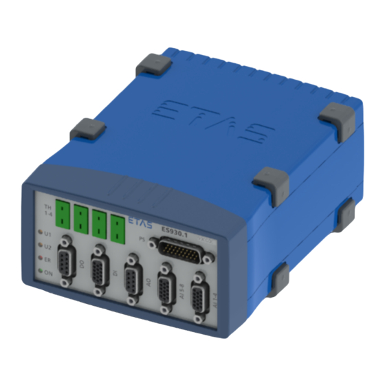
ETAS ES930.1 User Manual (139 pages)
Multi-I/O Module
Brand:
ETAS
| Category:
I/O Systems
| Size: 7 MB
Table of Contents
Table of Contents
3
About this Document
8
Classification of Safety Messages
8
Presentation of Instructions
8
Presentation of Supporting Information
8
Basic Safety Notices
9
General Safety Information
9
Requirements for Users and Duties for Operators
9
Intended Use
9
Fig. 3-1 ES930.1 Multi-I/O Module
14
Combination with the ES910 Prototyping Module
14
Integration in the Measuring Setup
14
Input and Output Channels
14
Overview
14
Hardware Description
14
Configuration and Data Acquisition
15
Properties
15
Decentral Cabling Concept
15
Inputs and Outputs
15
Simple Cabling Concept of Inputs and Outputs
16
Additional Properties
16
Module
17
Housing
17
Front Side
17
Rear Side
19
Overview of Function Groups
20
Fig. 3-4 ES930.1 Block Diagram
20
Power Supply
21
Power Supply of Module
21
Power Supply of Half-Bridges (Power Stages) at the "PS" Connection
21
Power Supply of a Single Module
21
Power Supply of Additional Modules Chained Via Ethernet
21
Switching the Module on and off
22
Es93X Modules in Mixed Module Chains
22
Data Transfer
23
Fig. 3-5 Message Format "XCP on UDP" (Schematic)
23
Signal Acquisition and Signal Conversion
25
Signal Acquisition and Signal Output
25
Requests
26
Fig. 3-6 Sampling of the Data (Fixed Raster)
26
Fig. 3-7 Oversampling at the Digital Input Channel
26
Signal Output
27
Synchronization of the Model Process of the ES910 Rapid Prototyping
27
Module
27
Limited Data Acquisition
27
Limited Data Transfer for MC Applications
27
Overload for Rapid Prototyping Applications
28
Fig. 4-1 Thermo Channels "TH1" to "TH4
29
A/D Converter
29
Cold-Junction Compensation with A/D Converter
29
Overview
29
Thermo Channels ("TH1-4" Connections)
29
Assemblies of the Thermo Channels
29
Open TC Detection
30
Measurement Error
30
Electrical Isolation
30
Digital Input Channels ("DI" Connection)
31
Assemblies of the Digital Input Channels
31
Overview
31
Fig. 5-1 Digital Input Channels
31
Timeout Detection
32
Fig. 5-2 Definition of Hysteresis for the Input Channel
32
Event Raster Source
32
Capture Unit
32
Counter Unit
32
Glitch Filter
32
Schmitt Trigger
32
Counter Overflow Detection
33
Electrical Isolation
33
Measuring Functions
34
Definitions of the Measuring Signals
34
Fig. 5-3 Active and Inactive State
34
Fig. 5-4 Active and Inactive Pulse
35
Fig. 5-5 Period, Starting with an Active-Inactive Edge
35
Fig. 5-6 Cycle, Starting with an Inactive-Active Edge and N=3
35
Overview of Measuring Functions
36
Fig. 5-7 Cycle, Starting with an Active-Inactive Edge and N=3
36
Measurement of the Signal State (State)
37
Fig. 5-8 Measurement of Active and Inactive State (Fixed Measure Rate)
37
Counter
38
Fig. 5-9 Counting of Inactive-Active Edges
39
Fig. 5-10 Counting of Active-Inactive Edges
39
Fig. 5-11 Counting of Inactive-Active and Active-Inactive Edges
39
Time Measurement
40
Fig. 5-13 Measurement of Active Time During the Last Period
41
Fig. 5-14 Measurement of Active Time of a Cycle
41
Fig. 5-15 Measurement of Active Time between Two Sampling Points
41
Fig. 5-16 Measurement of Active Time until the Last Current Sampling Point
41
Calculation of Cycle Duration, Frequency and Scan Ratio
42
Calculation of the Speed
43
Fig. 5-17 16-2 "Speed Sensor Wheel
43
Fig. 5-18 Principle of the Input Signal of a "Speed Sensor Wheel
44
Analog Input Channels ("AI 1-4"/"AI 5-8" Connections)
45
Channel Groups
45
Assemblies of the Analog Input Channels
45
Overview
45
Input Range (Level Adjustment)
45
Anti-Aliasing Filter
45
Fig. 6-1 Analog Input Channels "AI 1" to "AI 4
45
A/D Converter
46
Digital Filter
46
Definitions
47
Maximum Input and Common Mode Voltages
47
Compensation of Group Runtime
47
Example
48
Electrical Isolation
48
Fig. 6-3 Maximum Input and Common Mode Voltages
48
Outputs to the Sensor Power Supply
49
Channel Groups
49
Assemblies of the Sensor Supply Channels
49
Overview
49
D/A Converter
49
Fig. 7-1 Sensor Supply Voltage Channel
49
Behavior for Rapid Prototyping Applications
50
Electrical Isolation
50
Overload Detection
50
Overcurrent Protection
50
Assignment of Channels
50
Fig. 8-1 Analog Output Channels
51
Fig. 9-1 Block Diagram of a Digital Output Channel
53
Fig. 9-2 Simplified Diagram of the Output Channel Characteristics
56
Fig. 9-3 "Digital Output" Functionality
58
Fig. 9-4 "PWM Output" Functionality
58
Fig. 9-5 "Pulse Out" Functionality
58
Fig
59
Fig. 10-1 Half-Bridge Channel Group (Power Stage Group)
59
Fig. 10-2 Current Measurement Channel
61
Protection in the CBAV422.1 Cable
65
Protection of the Half-Bridges
65
Safeguarding the "PS" Total Assembly
65
Startup
66
Installation and Blocking
66
General Installation Recommendations
66
Fastening the Module Onto a Carrier System
66
Fig. 11-1 Prying off the Plastic Foot
66
Connecting Several Modules Mechanically
67
Fig. 11-2 Threaded Blind Hole
67
Fig. 11-3 Connecting the ES930.1 with Another Module
68
Fig. 11-4 ES930.1 and Additional ETAS Modules for MC Applications
69
ES930.1 with ES910 and Additional ETAS Modules for Rapid Prototyping
69
ES930.1 with Additional ETAS Modules (MC Applications)
69
Applications
69
Cabling
70
Cabling of the ES930.1 for MC Applications
71
Fig. 11-6 Cabling of the ES930.1 with ETAS Modules (MC Application)
71
Cabling of ES930.1 for RP Applications
72
Fig. 11-7 Cabling of ES930.1 with ETAS Modules (RP Application)
72
Daisy Chain Connections ("IN", "OUT")
73
Inputs (Connections "DI", "AI 1-4" and "AI 5-8")
74
Outputs (Connections "DO" and "AO")
74
Half-Bridges ("PS" Connection)
74
SERVICE" Connection
74
Protection of the "PS" Assembly
75
LED Displays
75
Handling of Problems
75
Problems with the ES930.1
76
Problems and Solutions
79
Network Adapter Cannot be Selected Via Network Manager
79
Search for Ethernet Hardware Fails
80
Personal Firewall Blocks Communication
82
Technical Data
85
Fig
85
Labels on the Product
85
Product Label
85
Labeling of the Connections
86
Used Symbols
86
CE Conformity
87
Declarations of Conformity
87
Rohs Conformity
87
Standards and Norms
87
Declarable Substances
88
Taking the Product Back and Recycling
88
Cleaning the Product
89
Maintenance the Product
89
Mechanical Data
89
Use of Open Source Software
89
Environmental Conditions
90
Hardware
90
System Requirements
90
Software
91
Electrical Data
92
"DI" Connection
103
Fig. 14-7 "TH1-4" Connection
108
Fig. 14-10 Cable for Inputs and Outputs
111
Fig. 14-11 CBAV420.1 Cable with Wiring Plan
112
Di_Ch1
113
Di_Ch1_Gnd
113
Di_Ch2
113
Di_Ch2_Gnd
113
Di_Ch3
113
Di_Ch3_Gnd
113
Di_Ch4
113
Di_Ch4_Gnd
113
Fig. 14-12 CBAV421.1 Cable with Wiring Plan
116
Fig. 14-13 CBAV422.1 Cable with Wiring Plan
118
Fig. 14-14 CBE400.2 Cable
120
Fig. 14-15 CBE401.1 Cable
120
Fig. 14-16 CBE430.1 Cable
120
Fig. 14-17 CBE431.1 Cable
121
Fig. 14-18 CBEX400.1 Cable
121
Fig. 14-19 CBEP410.1 Cable
123
Fig. 14-20 CBEP4105.1 Cable
123
Fig. 14-21 CBEP415.1 Cable
124
Fig. 14-22 CBEP4155.1 Cable
124
Fig. 14-23 CBEP420.1 Cable
125
Fig. 14-24 CBEP4205.1 Cable
125
Fig. 14-25 CBEP425.1 Cable
126
Fig. 14-26 CBEP4255.1 Cable
126
Figures
134
Advertisement
Advertisement
Related Products
ETAS ES922.1
ETAS ES5321.1
ETAS ES5436.1
ETAS ES5350.1
ETAS ES5372.1
ETAS ES1310.1
ETAS ES5321.2
ETAS ES910.3-A
ETAS FlexRay ES920.1
ETAS ES921.1
ETAS Categories
Control Unit
Computer Hardware
Measuring Instruments
Recording Equipment
I/O Systems
More ETAS Manuals
Login
Sign In
OR
Sign in with Facebook
Sign in with Google
Upload manual
Upload from disk
Upload from URL