ESAB PEK A2 Instruction Manual
Hide thumbs
Also See for PEK A2:
- Instruction manual (74 pages) ,
- Instruction manual (16 pages) ,
- Instruction manual (18 pages)

Subscribe to Our Youtube Channel
Related Manuals for ESAB PEK A2


Summary of Contents for ESAB PEK A2
- Page 1 A2, A6 Control panel Instruction manual 0460 949 074 GB 090529 Valid from program version 1.00...
-
Page 2: Table Of Contents
1 INTRODUCTION ........... 1.1 Control panel . - Page 3 6 FUNCTION EXPLANATIONS ........6.1 CA, constant welding current .
- Page 4 9 TOOLS ............9.1 Error log .
-
Page 5: Introduction
INTRODUCTION To benefit as much as possible from your welding equipment, we recommend that you read this instruction manual. For general information about operation, see the instruction manual for the control unit, automatic welding machine, column and boom or power source. The text presented in the display is available in the following languages: English, Swedish, Finnish, Norwegian, Danish, German, French, Italian, Dutch, Spanish, Portuguese, Hungarian, Polish, American, Czech, Chinese and Russian. -
Page 6: Keys And Knobs
16 Soft keys 17 Display 1.1.1 Keys and knobs Menu The Menu key always takes you back to the main menu in the relevant process: PROCESS REGULATION TYPE WIRE TYPE Fe SOLID WIRE DIMENSION 3.0 mm CONFIGURATION " TOOLS " FAST MEASURE MEMORY... -
Page 7: First Step
Travel motion Key for travel motion in the direction of welding where the symbol is indicated on the weld equipment. To stop travel motion press The LED illuminates during travel motion. Fast motion Key for fast motion of wire feed or travel motion. The LED illuminates during fast motion. -
Page 8: Unit Of Measurements
Press Menu to access the main menu. Position the cursor using the positioning PROCESS knob on the CON- REGULATION TYPE FIGURATION row. WIRE TYPE Fe SOLID WIRE DIMENSION 3.0 mm CONFIGURATION " TOOLS " FAST MEASURE MEMORY MODE Press ENTER to confirm the selection. - Page 9 Press Menu to access the main menu. Position the cursor using the positioning PROCESS knob on the CON- REGULATION TYPE FIGURATION row. WIRE TYPE Fe SOLID WIRE DIMENSION 3.0 mm CONFIGURATION " TOOLS " FAST MEASURE MEMORY MODE Press ENTER to confirm the selection.
-
Page 10: Display
Display PROCESS REGULATION TYPE WIRE TYPE Fe SOLID WIRE DIMENSION 0.8 mm CONFIGURATION " TOOLS " FAST MEASURE MEMORY MODE Cursor The control panel’s cursor is presented as a black field around the text, with the selected text turning white. The cursor is displayed in the instruction manual with bold text. -
Page 11: General Information About Settings
General information about settings There are three types of setting: Setting of numerical values Setting of given alternatives Setting of ON/OFF mode 1.4.1 Setting of numerical values The settings knobs are used to increase or decrease the set values when setting numerical values. -
Page 12: Menus
MENUS The control panel uses several different menus: Main menu Configuration menu Tools menu Weld data setting menu Measurements menu Weld data memory menu Fast mode menu The menu trees are displayed on page 54 and onwards. During start−up, a start−up screen containing information about the current program version is displayed briefly. -
Page 13: Configuration Menu
2.1.1 Configuration menu Main menu ³ Configuration In the CONFIGUR- CONFIGURATION ATION menu it is LANGUAGE ENGLISH possible to change CODE LOCK language, change GENERAL CONFIGURATION " password, make MACHINE CONFIGURATION general settings, make " CABLE LENGTHS machine adjustments " etc. -
Page 14: Measurements Menu
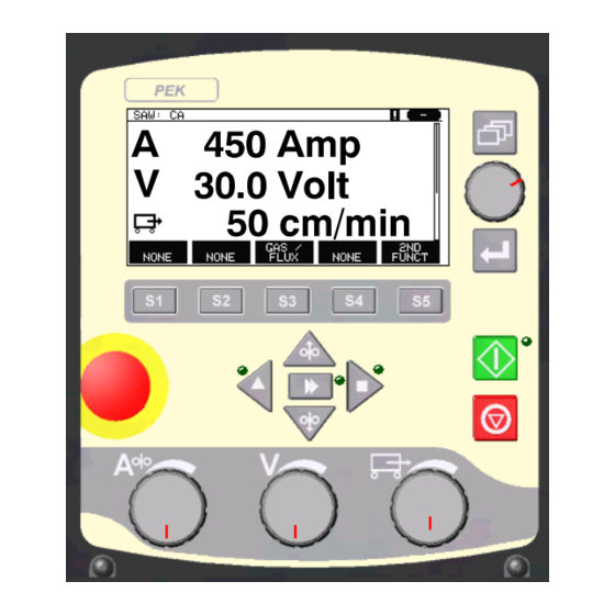
2.1.4 Measurements menu Main menu ³ In MEASURE, you can view measured values for various welding parameters while welding is in progress. A 450 AMP SAW: CA 450 Amp Measured welding current 30.0 Volt 30.0 Volt Measured arc voltage 50 cm/min 50 cm/min Measured travel speed GAS /... -
Page 15: Weld Data Memory Menu
In the measurement display one can also see the set values if the soft key SET VALUES is activated. For activating see chapter ”Setting soft keys“ 8.2.3 . 300 cm/min SAW: CA 300 cm/min Set wire feed speed 20.0 Volt V 20.0 Volt Set arc voltage 30 cm/min... -
Page 16: Fast Mode Menu
2.1.6 Fast mode menu Main menu ³ In the FAST MODE menu, you can “link” 450 Amp soft keys to weld data memory positions. These settings are 30.0 Volt carried out in the Configuration menu. The number of the 50 cm/min selected memory position is displayed in the top right corner. -
Page 17: Settings For Submerged Arc Welding With Ca
Settings for submerged arc welding with CA Settings Setting range In steps of Value after resetting Arc voltage* 14 − 50 V 0.1 V (1V) 30 V Welding current* 0 − 3200 A 400 A Travel speed* 0 − 200 cm/min 1 cm/min 50 cm/min Welding direction... -
Page 18: Gas Metal Arc Welding
Settings Setting range In steps of Value after resetting Flux post−flow 0 − 99.0 s 0.1 s Crater filling OFF or ON − Crater filling time 0 − 10 s 0.01 s Burnback time 0 − 10 s 0.01 s 0.10 s Stop phases OFF or ON... -
Page 19: Settings For Gas Metal Arc Welding With Cw
Settings Setting range In steps of Value after resetting Start phases OFF or ON − Open−circuit voltage OFF or ON − Maximum open−circuit voltage 5 − 60 V 0.1 V 50 V Stop data Gas post−flow 0 − 99.0 s 0.1 s 2.0 s Crater filling... -
Page 20: Gouging
GOUGING Main menu ³ Process With arc air gouging, a special electrode comprising a carbon rod with a copper casing is used. An arc is formed between the carbon rod and the work piece, which melts the material. Air is supplied so that the melted material is blown away. When the GOUGING process is selected, you can choose between two control methods by marking REGULATION TYPE using the positioning knob and pressing ENTER. -
Page 21: Settings For Gouging With Cw
Settings Setting range In steps of Value after resetting Setting limits − − − Measure limits − − − *) The setting range is dependent on the product used. Settings for gouging with CW Settings Setting range In steps of Value after resetting Arc voltage*... -
Page 22: Wire / Electrode Dimension
Wire / electrode dimension The table on page 58 shows the wire / electrode dimensions that can be selected. Selected dimensions have a great impact on the start procedure and crater filling. When welding with other wire dimensions other than those found in the table, select one that has a dimension close to one in the list. -
Page 23: Start Type
6.11 Start type There are two options for start type: Direct start, means that the travel speed starts when the arc is struck. Scrape start, means that the travel speed starts at the same time as wire feed. − Start type is selected in the weld data setting menu under start data. 6.12 Wire creep start Wire creep start is used to set the desired creep speed on the electrode motor upon... -
Page 24: Gas Post−Flow
6.16 Gas post−flow This controls the time during which shielding gas flows after the arc is extinguished. − Gas post−flow is set in the weld data setting menu under stop data. 6.17 Air post−flow This controls the time during which air flows after the arc is extinguished. −... -
Page 25: Dynamic Regulation
6.21 Dynamic regulation The dynamic regulation function is developed for multiple electrode welding and alters the characteristics of the power source. The characteristics of the power source are calculated from the set wire data. − Dynamic regulation is selected in the weld data setting menu under stop data. 6.22 Setting limits For information about setting limits see chapter 9.4 ”Setting limit editor”... -
Page 26: Store
It is possible to store up to 255 sets of weld data in the control panel. Each set is given a number from 1 to 255. You can also delete, copy, change and name data sets and recall a set of weld data to the working memory. -
Page 27: Recall
If a data set is already WELD DATA MEMORY stored in the selected 1 − location, you will be 2 − asked if you want to 3 − overwrite that set or 4 − not, YES or NO. 5 − (SAW) 6 −... -
Page 28: Delete
This icon in the measurement display shows which memory position number has been recalled. Delete It is possible to delete one or more data sets in the memory menu. Deleting a data set. WELD DATA MEMORY Select the data set. 1 −... -
Page 29: Copy
Copy To copy the content of a weld data set to a new memory position, proceed as follows: Select the memory WELD DATA MEMORY position you want to 1 − copy and press 2ND 2 − FUNCT. 3 − 4 − 5 −... -
Page 30: Name
We are now going to copy the content of memory position 5 to position 50. Use the positioning knob to scroll to the selected memory position, in this case position 50. Press YES. WELD DATA MEMORY 44− 45 − 46 − 47 −... -
Page 31: Edit
Edit To edit the content of a weld data set, proceed as follows: Mark the memory posi- WELD DATA MEMORY tion you wish to 1 − change. Press 2ND 2 − FUNCT and then EDIT. 3 − 4 − 5 − (SAW) 6 −... -
Page 32: Configuration Menu
The following menu appears: In this example we SAW WELD DATA SETTING change the welding VOLTAGE 20.0 V current from 400 A to CURRENT 500 A 500 A. TRAVEL SPEED 0 cm/min Press QUIT twice. DIRECTION START DATA " STOP DATA "... -
Page 33: Lock Code Status
8.1.1 Lock code status In lock code status, you can activate/deactivate the lock function without deleting the existing lock code in the event you deactivate the function. If no lock code is stored and you try to activate the code lock, the keyboard is displayed for entering a new lock code. -
Page 34: General Settings
General settings Main menu ³ Configuration menu ³ General settings In this menu you can set: Fast mode soft keys, see chapter 8.2.1 Quality data log to file, see chapter 8.2.2 Setting soft keys, see chapter 8.2.3 Automatic weld data storage, see chapter 8.2.4 Unit of length, see chapter 1.2.2 “unit of measurement”... -
Page 35: Quality Data Log To File
Then scroll to the next row, ASSOCIATED WELD DATA. Here you can browse through the weld data sets that are stored in the weld data memory. Selected the desired weld data number using the setting knobs. Press STORE to save. To delete the stored set, press DELETE. -
Page 36: Auto Save Mode
When you allocate functions to these keys, they are numbered from the left as follows: FUNCT S1 2ND S2 2ND S3 2ND S4 2ND FUNCT FUNCT FUNCT FUNCT FUNCT To allocate a new function to a soft key, proceed as follows: Position the cursor on SOFT KEYS SETUP the row with the soft... -
Page 37: Product Code
8.3.1 Product code In the PRODUCT MACHINE CONFIGURATION CODE menu it is poss- PRODUCT CODE A2TFX ible to select the auto- WIRE FEED AXIS" matic welding machine, TRAVEL AXIS" column and boom, TANDEM roller bed or positioner to be used. QUIT When selecting product code, the correct motor type and gear ratio for the used gearbox in the relevant product are selected automatically. -
Page 38: Travel Axis
FREE 2 AXIS FREE 3 AXIS Motor 5035 38 RPM 5035 38 RPM Gear 1 49:1 49:1 Gear 2 Diameter feed rollers 49 mm 49 mm Pulse sensor 28 ppr 28 ppr Low manual speed 150 cm/min 150 cm/min High manual speed 300 cm/min 300 cm/min 8.3.3... -
Page 39: Tandem
8.3.5 Tandem Used when welding with two welding heads. Position the cursor on MACHINE CONFIGURATION the TANDEM row and PRODUCT CODE A2TFX press ENTER. WIRE FEED AXIS" Select ON using the TRAVEL AXIS" positioning knob and TANDEM press ENTER. b WELDING HEAD HEAD b WELD HEAD OFFSET 20 mm... - Page 40 Specify the values to weld with two welding heads as follows: Position the cursor on MACHINE CONFIGURATION the WELDING HEAD PRODUCT CODE A2TFX row. WIRE FEED AXIS" Select whether the set- TRAVEL AXIS" ting is to apply to TANDEM ”master” control unit b WELDING HEAD HEAD HEAD or ”slave”...
-
Page 41: Cable Length
When the interval has been passed, fault code 54 is displayed in the error log. Reset by pressing RESET. When TOTAL RUNNING TIME LIMIT is selected instead of the number of starts, an authorised ESAB service technician is contacted. MAINTENANCE CONTACT TIP CHANGE INTERVAL... -
Page 42: Tools
TOOLS Main menu ³ Tools This menu contains the following sub−menus: Error log, see chapter 9.1 Export/Import, see chapter 9.2 File manager, see chapter 9.3 Edit setting limits, see chapter 9.4 Edit measure limits, see chapter 9.5 Production statistics, see chapter 9.6 Quality functions, see chapter 9.7 Calendar, see chapter 9.8 User accounts, see chapter 9.9... -
Page 43: Delete Error Message
ERROR LOG Index Date Time Unit Error 081120 11:24:13 081120 10:24:18 081121 13:24:18 Error in battery−driven memory DELETE QUIT 9.1.1 Delete error message In order to delete error messages, press DELETE ALL. All rows are emptied from the error log. 9.1.2 Units = Power source... -
Page 44: Export/Import
Error Description code Internal communication error (warning) The load on the system’s CAN−bus is temporarily too high. The power source may have lost contact with the control unit. Action: Check that all the equipment is correctly connected. If the error persists, send for a service technician. -
Page 45: File Manager
Select the row with the EXPORT/IMPORT information that is to be WELD DATA SETS transferred. Press SYSTEM SETTINGS EXPORT or IMPORT, SETTING LIMITS depending on whether MEASURE LIMITS the information is to be ERROR LOG exported or imported. QUALITY FUNCTION LOG PRODUCTION STATISTICS EXPORT IMPORT... -
Page 46: Delete A File/Folder
Select a folder or file FILE MANAGER and press ALT. WeldData NEW FOLDER ErrorLog.xml QData.xml XWeldoffice.dat INFO UPDATE ALT. QUIT This list is displayed when you have pressed ALT. COPY PASTE DELETE RENAME NEW FOLDER 9.3.1 Delete a file/folder Select the file or folder that is to be deleted and press ALT. Select DELETE and press ENTER. -
Page 47: Copy And Paste Files
9.3.4 Copy and paste files Select the file that is to be copied and press ALT. Select COPY and press ENTER. COPY PASTE DELETE RENAME NEW FOLDER Position the cursor in the folder in which the copied file is to be located and press ALT. -
Page 48: Measure Limits Editor
When the values have been adjusted, press STORE. When asked if the limit value is to be saved at the selected storage point, press NO or YES. The storage point’s values can be seen under the line at the bottom. With the AUTO soft key, the parameters are set automatically according to the most recently used parameters. -
Page 49: Production Statistics
In the dialogue box, you are asked if you want to store the selected storage point. Press YES to save the value. The storage point’s values can be seen under the line at the bottom. MEASURE LIMITS 1 − SAW 2 −... -
Page 50: Quality Functions
When you press RESET, all counters are reset. Date and time show the most recent reset. If you do not reset the counters, these are all automatically reset when one of them has reached its maximum value. Maximum counter values Time 999 hours, 59 minutes, 59 seconds Weight... -
Page 51: Store Quality Data
9.7.1 Store quality data Main menu ³ Tools ³ Export / Import The files that are produced in the control panel are stored as xml files. The USB memory must be formatted as FAT32 in order to work. Insert a USB memory in the control panel, see chapter “File manager”. -
Page 52: User Accounts
User accounts Main menu ! Tools ! User accounts Occasionally it is particularly important from a quality perspective that the product cannot be used by unauthorised parties. User name, account level and password are registered in this menu. Select USER NAME USER ACCOUNTS and press ENTER. -
Page 53: Unit Information
9.10 Unit information Main menu ! Tools ! Unit information I this menu you can see the following information: Machin ID Node ID 2 = power source 6 = wire feed and travel motion (motor board) 8 = control panel Software version UNIT INFORMATION Machine ID... -
Page 54: Menu Structure
Control panel Menu structure NO TAG54 SAW (CA) − Process − Regulation type − Wire type − Wire dimension − Configuration, see page 57 − Tools, see page 57 Voltage Current Travel speed Direction Start data − flux preflow − start type −... - Page 55 Control panel GMAW (CA) − Process − Regulation type − Wire type − Wire dimension − Configuration, see page 57 − Tools, see page 57 Voltage Current Travel speed Direction Start data − gas preflow − start type − wire creep start −...
- Page 56 Control panel GOUGING (CA) − Process − Regulation type − Electrode dimension − Configuration, see page 57 − Tools, see page 57 Voltage Current Travel speed Direction Start data − air preflow − start type − wire creep start − start phases −...
- Page 57 Control panel NO TAG SAW, GMAW, GOUGING Configuration Tools Language Error log Code lock Export / Import General configuration File manager − fast mode soft buttons Setting limit editor − quality data log to file Measure limit editor − soft keys setup Production statistics −...
-
Page 58: Wire Dimension
Wire dimension Submerged arc welding with constant ampere (SAW CA) Wire type Wire diameter (mm) Fe Solid 0.8 1.0 1.2 1.6 2.0 2.4 3.0 3.2 4.0 5.0 6.0 Fe Solid Twin 2x0.8 2x1.0 2x1.2 2x1.6 2x2.0 2x2.4 2x3.0 2x4.0 2x5.0 Fe Flux Cored 0.8 1.0 1.2 1.6 2.0 2.4 3.0 3.2 4.0 Fe Flux Cored Twin... -
Page 59: Ordering Number
0460 949 085 Instruction manual SK 0460 949 089 Instruction manual EE 0460 949 090 Instruction manual LV 0460 949 091 Instruction manual SI 0460 949 092 Instruction manual LT Instruction manuals are available on the Internet at www.esab.com − 59 − Edition 090529 bi24o... - Page 60 ESAB subsidiaries and representative offices Europe NORWAY Asia/Pacific Representative offices AS ESAB AUSTRIA BULGARIA CHINA Larvik ESAB Ges.m.b.H ESAB Representative Office Shanghai ESAB A/P Tel: +47 33 12 10 00 Vienna−Liesing Sofia Shanghai Fax: +47 33 11 52 03 Tel: +43 1 888 25 11...
Need help?
Do you have a question about the PEK A2 and is the answer not in the manual?
Questions and answers