Table of Contents
Advertisement
Quick Links
Advertisement
Table of Contents

Related Manuals for ESAB EAC 30


Summary of Contents for ESAB EAC 30
- Page 1 EAC 30 Control panel Instruction manual 0448 311 001 GB 20240206...
-
Page 2: Table Of Contents
ICE wire start delay ......................... Travel speed ......................9.10 Welding direction ....................... 9.11 AC frequency ........................9.12 AC balance ........................9.13 AC offset ..................... 9.14 Flux pre-flow (SAW) ....................9.15 Gas pre-flow (GMAW) 0448 311 001 - 2 - © ESAB AB 2024... - Page 3 ......................11.3.4 Travel axis ....................... 11.3.5 External axis ....................... 11.3.6 Tandem ..................11.3.7 Parallel power sources ...................... 11.3.8 ICE wire feed ....................11.3.9 Node id settings ..................... 11.3.1 System information 0448 311 001 - 3 - © ESAB AB 2024...
- Page 4 High inductance ................... 13.14 Lost contact with the unit ......................13.15 Motor servo error ..........................OPTIONAL ............14.1 EAC 30 control unit as separate motor control ......................... ORDERING NUMBERS ............................. ACCESSORIES 0448 311 001 - 4 - © ESAB AB 2024...
-
Page 5: Introduction
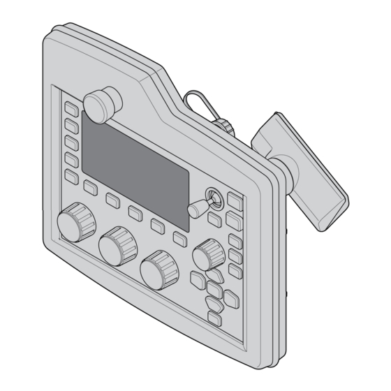
22. Switch between functions 10. Travel speed / Setting knob 23. Welding stop 11. Manual travel motion 24. Welding start 12. Switch between functions 25. Motion control joystick 13. Manual wire feed downwards 0448 311 001 - 5 - © ESAB AB 2024... -
Page 6: Controls
Travel speed setting knob The travel speed / frequency knob is used for increasing or decreasing set values. Manual travel motion buttons The buttons are used for manual travel motions. 0448 311 001 - 6 - © ESAB AB 2024... - Page 7 The right-hand knob is the positioning knob and is used to navigate menus. Press the knob to confirm a selection. Home menu Press the home menu button to enter the home menu. 0448 311 001 - 7 - © ESAB AB 2024...
- Page 8 Use the joystick to control the movement of the servo slides up/down and left/right. • Use the joystick to control the movement of the boom up and down and to rotate the boom. 0448 311 001 - 8 - © ESAB AB 2024...
-
Page 9: First Steps
behind the text. Symbols in the display 1. The active weld data setting 4. Recalled memory position number 2. Welding direction 5. Scroll bar 3. A fault has occured, see event log 0448 311 001 - 9 - © ESAB AB 2024... -
Page 10: Select Language
The control panel is set to metric measurement on delivery. To change measurement unit, proceed as follows: Press the home menu button to access the main menu, and position the cursor on the CONFIGURATION row, using the positioning knob. 0448 311 001 - 10 - © ESAB AB 2024... - Page 11 QUALITY DATA LOG TO FILE SOFT KEYS SETUP► AUTO SAVE MODE UNIT OF LENGTH METRIC Position the cursor on the row for the correct measurement and press the positioning knob. METRIC INCH. 0448 311 001 - 11 - © ESAB AB 2024...
-
Page 12: Technical Data
Enclosure class The IP code indicates the enclosure class, i.e. the degree of protection against penetration by solid objects or water. Equipment marked IP23 is intended for indoor and outdoor use. 0448 311 001 - 12 - © ESAB AB 2024... -
Page 13: Menu
CONFIGURATION► TOOLS► MEASURE MEMORY FAST MODE Configuration menu MAIN MENU » CONFIGURATION In the CONFIGURATION menu it is possible to change language, change password, make general configurations, make machine adjustments etc. 0448 311 001 - 13 - © ESAB AB 2024... -
Page 14: Tools Menu
In the weld data setting menu, SET, it is possible to change different welding parameters. The menu has different appearances depending on which welding process is selected. An example of the menu: 0448 311 001 - 14 - © ESAB AB 2024... -
Page 15: Measurement Menu
MEMORY In the WELD DATA MEMORY menu you can store, recall, delete and copy various set weld data. The weld data sets can be stored in 255 different memory positions. 0448 311 001 - 15 - © ESAB AB 2024... -
Page 16: Fast Mode Menu
CONFIGURATION menu. The number of the selected memory position is displayed in the top right corner. WELD DATA 1 WELD DATA 2 WELD DATA 3 WELD DATA 4 2ND FUNCT 0448 311 001 - 16 - © ESAB AB 2024... -
Page 17: Submerged Arc Welding (Saw)
REGULATION TYPE using the positioning knob and pressing the knob. Choose between constant welding current CA or constant wire feed CW or constant current CC. 0448 311 001 - 17 - © ESAB AB 2024... -
Page 18: Gas Metal Arc Welding (Gmaw)
CW, see explanation in "CA, constant amperage" and "CW, constant wire feed". GMAW PROCESS GMAW REGULATION TYPE WIRE TYPE Fe SOLID WIRE DIMENSION 0.8 mm CONFIGURATION► TOOLS► 0448 311 001 - 18 - © ESAB AB 2024... -
Page 19: Gouging
CC. For GOUGING MODE it is possible to choose between AUTO and N7500. GOUGING PROCESS GOUGING METHOD REGULATION TYPE WIRE DIMENSION 8.0 mm GOUGING MODE N7500 CONFIGURATION► TOOLS► 0448 311 001 - 19 - © ESAB AB 2024... -
Page 20: Electro Slag Welding
» PROCESS Electro slag welding (ESW) is a single pass welding process. PROCESS METHOD REGULATION TYPE WIRE TYPE SS Strip WIRE DIMENSION 30×0,5 mm CONFIGURATION► TOOLS► MEASURE MEMORY FAST MODE 0448 311 001 - 20 - © ESAB AB 2024... -
Page 21: Joint-Tracking
Joint-tracking with edge control is used for welding fillet welds and similar joints, see also the joint table. The stop screws are tightened to the stop point. 0448 311 001 - 21 - © ESAB AB 2024... -
Page 22: Joint-Tracking With Groove Control
Examples of different types of joint and of the guide finger’s application against the guiding edges. Joint type Setting, control box Double flanged butt weld UpDownLeft UpDownRight I-weld (A=guide bar) UpDownLeft UpDownRight V-weld UpDownLeftRight 1/2 V-weld UpDownLeftRight 1/2 V-weld UpDownLeft UpDownRight U-weld UpDownLeftRight 0448 311 001 - 22 - © ESAB AB 2024... -
Page 23: Position For Welding Start
3) Operate the guide finger horizontally using the motion control joystick on the control unit, until the finger is above a suitable start position, see the illustration below. UpDown joint-tracking alone the guide finger is positioned where the start of the weld is required to be. 0448 311 001 - 23 - © ESAB AB 2024... -
Page 24: Positioning For Welding Start (With Inductive Joint-Tracking)
Positioning for welding start (with inductive joint-tracking) The product must be configured before inductive joint-tracking is possible. Contact authorised ESAB service personnel for configuration. 1) Align the welding equipment into position in relation to the weld joint so that the working range of the slide cross covers the whole height and lateral deviation of the joint from starting point to the stopping point for welding. -
Page 25: Function Explanations
ICE wire feed speed is used to set the percentage of the ICE wire of the hot wire speed. • The ICE feed speed is set in the measurement display, weld data setting menu, or fast mode menu. 0448 311 001 - 25 - © ESAB AB 2024... -
Page 26: Ice Wire Start Delay
Gas pre-flow (GMAW) This controls the time during which shielding gas flows before the arc is struck. • Gas pre-flow is set in the weld data setting menu under start data. 0448 311 001 - 26 - © ESAB AB 2024... -
Page 27: Start Adjust
In percent of set travel speed • ICE wire speed % In percent of live/hot wire speed Start phases are set in the weld data setting menu under start data. 0448 311 001 - 27 - © ESAB AB 2024... -
Page 28: Flux Post-Flow (Saw)
Travel speed % • Travel speed % In percent of set travel speed In percent of set travel speed Stop phases are set in the weld data setting menu under stop data. 0448 311 001 - 28 - © ESAB AB 2024... -
Page 29: Regulation Parameters
If the limits are exceeded during welding, a warning message will appear on the display, which will also be recorded in the error log. 0448 311 001 - 29 - © ESAB AB 2024... -
Page 30: Step Function
The number of steps during one rotational turn. OVERLAP The length of the overlap of one rotational turn. MANUAL STEP LENGTH The length of one manual step (minimum setting 1 mm) (for singular manual adjustments during welding) 0448 311 001 - 30 - © ESAB AB 2024... -
Page 31: Intermittent Welding
If the number of welds is set to “0”, the intermittent welding sequence continues until the user stops the welding using the red weld stop button. 0448 311 001 - 31 - © ESAB AB 2024... -
Page 32: Memory Management
Position 1 is displayed. Turn one of the settings knobs until you reach position 5. Press STORE. WELD DATA MEMORY STORE 2ND FUNCT The following screen appears in the display. The weld data set is now stored as number 5. 0448 311 001 - 32 - © ESAB AB 2024... -
Page 33: Recalling A Stored Data Set
SAW: CA: FE SOLID: 3.0 mm 30.0 V: 450 A: 50 cm/min STORE RECALL DELETE 2ND FUNCT Press to confirm that you want to recall data set number 5. 0448 311 001 - 33 - © ESAB AB 2024... -
Page 34: Deleting Data Set
5 - (SAW) SAW: CA: FE SOLID: 3.0 mm 30.0 V: 450 A: 50 cm/min STORE RECALL DELETE 2ND FUNCT Press to confirm that you want to delete. 0448 311 001 - 34 - © ESAB AB 2024... -
Page 35: Copying Content Of A Weld Data Set To A New Memory Position
We are now going to copy the content of memory position 5 to position 50. Select memory position 1 and scroll through using one of the settings knobs to the selected memory position; in this case, position 50. Press YES. 0448 311 001 - 35 - © ESAB AB 2024... -
Page 36: Naming A Stored Weld Data Set
I J K L M N O P Q R S T U V W X Y Z 0 1 2 3 4 5 6 7 8 9 SPACE CAPS 0 (MAX 40) DELETE SYMBOL DONE 0448 311 001 - 36 - © ESAB AB 2024... -
Page 37: Editing Content Of A Weld Data Set
0 cm/min DIRECTION ■ START DATA► STOP DATA► DYNAMIC REGULATION AUTO SETTING LIMIT► MEASURE LIMITS► The setting for weld data number 5 has now been edited and stored. 0448 311 001 - 37 - © ESAB AB 2024... -
Page 38: Configuration Menu
You will then move to the menu with the keyboard, where you can enter the code. Press the positioning knob after each character, and confirm the code by pressing the positioning knob again. The following text box appears: 0448 311 001 - 38 - © ESAB AB 2024... -
Page 39: Specify/Edit Lock Code
Selected the desired weld data number using the setting knobs. Press STORE to save. To delete the stored set, press DELETE. 0448 311 001 - 39 - © ESAB AB 2024... -
Page 40: Quality Data Log To File
Direction • Remote I/O Used when you want to control EAC 30 and a welding power source via an external I/O unit. • External axis To be activated when there is an external I/O unit for controlling a roller bed, for example. - Page 41 A pop-up menu shows the function selections. Select using the positioning knob and press the knob. SOFT KEY SETUP SOFT KEYS FUNCTION NONE NONE NONE NONE S1 2ND FUNCT NONE S2 2ND FUNCT NONE S3 2ND FUNCT NONE S4 2ND FUNCT NONE 0448 311 001 - 41 - © ESAB AB 2024...
-
Page 42: Auto Save Mode
Saving weld data manually in a memory position disables the next automatic save. The memory position in which the weld data set is stored is displayed in the top right corner of the measure screen. 0448 311 001 - 42 - © ESAB AB 2024... -
Page 43: Machine Configuration
2 motors to the actuator board. One for wire feed and one for travel motion. • Motor Control Optional configuration to use the control unit for separate motor control without a power source. • EWHC 1000 0448 311 001 - 43 - © ESAB AB 2024... -
Page 44: Wire Feed Axis 1
11.3.3 Wire feed axis 2 USER DEF.AXIS Motor VEC 4000 Gear 1 156:1 Gear 2 Diameter feed rollers 49 mm Pulse sensor 32 ppr Low manual speed 150 cm/min High manual speed 300 cm/min 0448 311 001 - 44 - © ESAB AB 2024... -
Page 45: Travel Axis
High manual speed 200 cm/min 200 cm/min 200 cm/min Frequency ratio 85:50 85:50 85:50 Motor 2000 rpm 2000 rpm 2000 rpm Weld diameter 1000 mm 1000 mm Roller diameter 1000 mm 0448 311 001 - 45 - © ESAB AB 2024... -
Page 46: Tandem
If ON is selected it means that one only need start the control unit for the front welding head. The rear one is started automatically. If OFF is selected all the welding heads must be started using the relevant control unit. 0448 311 001 - 46 - © ESAB AB 2024... -
Page 47: Parallel Power Sources
To be able to set up power sources in parallel, only the power sources that are to be connected should have power on and be active on the CAN2 bus. PARALLEL POWERSOURCES PARALLEL POWERSOURCES Number of power sources Parallel couple ID Parallel status Number of power sources 0448 311 001 - 47 - © ESAB AB 2024... -
Page 48: Ice Wire Feed
11.3.8 ICE wire feed NOTE! ICE option is only available with an ICE license. Contact ESAB for more information. The option ICE WIRE FEED ON can be selected in the machine configuration menu. If ICE wire feed... -
Page 49: Node Id Settings
11.3.9 Node id settings If there are I/O nodes in the system the ID numbers are given here. NODE ID SETTINGS I/O NODE 1 ID I/O NODE 2 ID 0448 311 001 - 49 - © ESAB AB 2024... -
Page 50: System Information
Change the value using the setting knobs. When the interval has been passed, fault code 54 is displayed in the error log. When TOTAL RUNNING TIME LIMIT is selected instead of the number of starts, an authorised ESAB service technician is contacted. MAINTENANCE CONTACT TIP CHANGE INTERVAL 0 Welds └... -
Page 51: Measure-Values Filter Factor
FOUR. Select the preferred filter factor using the positioning knob and press the knob. CONFIGURATION LANGUAGE ENGLISH CODE LOCK► GENERAL CONFIGURATION► MACHINE CONFIGURATION► CABLE LENGTHS► MAINTENANCE► MEASURE-VALUES FILTER FACTOR FOUR 0448 311 001 - 51 - © ESAB AB 2024... -
Page 52: Tools Menu
EVENT HANDLING » ACTIVE ERRORS The Active errors menu shows only the errors active for the moment. ACTIVE ERRORS Error nr Node ID Device type powersource powersource Error nr 78 0448 311 001 - 52 - © ESAB AB 2024... -
Page 53: Export Import
The control panel remembers where you were the last time you used file manager, so that you return to the same place in the file structure when you come back. 0448 311 001 - 53 - © ESAB AB 2024... - Page 54 I J K L M N O P Q R S T U V W X Y Z 0 1 2 3 4 5 6 7 8 9 SPACE CAPS ErrorLog.xml 12 (MAX 40) DELETE SYMBOL DONE 0448 311 001 - 54 - © ESAB AB 2024...
-
Page 55: Production Statistics
The most recently noted weld is presented in the display, although it is also possible to browse between other noted welds. All logs are deleted when you press RESET. 0448 311 001 - 55 - © ESAB AB 2024... -
Page 56: Calender
Date and time are set here. Select the row that is to be set: YEAR, MONTH, DAY, HOUR, MINUTES or SECONDS. Set the correct value using one of the setting knobs. Press SET. 0448 311 001 - 56 - © ESAB AB 2024... -
Page 57: User Accounts
If you choose not to have this function, but instead want the power source and control panel to be unlocked for all users, select USER ACCOUNTS OFF. 12.8 Unit information MAIN MENU » TOOLS » UNIT INFORMATION 0448 311 001 - 57 - © ESAB AB 2024... - Page 58 2.10A 1.40A POWER SOURCE 1 Seral Number 1452226815 UPDATE INFO UNIT INFORMATION Machine ID Node ID HW ID Version 2.10A 0.02m 0.02m POWER SOURCE 1 DSP 1 0448 311 001 - 58 - © ESAB AB 2024...
-
Page 59: Error Codes
Is reset at next weld start. If the error persists, send for a service technician. Current servo saturation The welding process has stopped because it has not advanced within 10 seconds. 0448 311 001 - 59 - © ESAB AB 2024... -
Page 60: Current Servo Saturation
High inductance 5010 Inductance is too high, depending on long welding cables and/or high weld data. Adjust the welding data. Lost contact with the unit 8117 Lost contact with a unit. 0448 311 001 - 60 - © ESAB AB 2024... -
Page 61: Motor Servo Error
If wire motor: check that the wire feed has not jammed or runs too fast. Check the motor cables. If travel motor: replace the pulse transducer. If the error persists, send for a service technician. 0448 311 001 - 61 - © ESAB AB 2024... -
Page 62: Optional
EAC 30 control unit as separate motor control EAC 30 as motor control without a power source is used when you want to have a travel control and possibility to give a start signal to an external power source. Remote is also active via ATAS I/O so you can control a roller bed with relay out for the start and an analogue reference for speed. - Page 63 Remote via ATAS I/O and external axis for controlling a roller bed can also be used together with motor control. SAW 0.8 mm : EXT ■ 7 REMOTE IO DIR. SQUARE EXT. AXIS SET VALUES 2ND FUNCT 0448 311 001 - 63 - © ESAB AB 2024...
- Page 64 PRODUCT CODE Motor control WIRE FEED AXIS 1► TRAVEL AXIS► EXTERNAL AXIS► Motor card Start signal to external equipment’s as the power source is located on connector X1.15-16. 0448 311 001 - 64 - © ESAB AB 2024...
-
Page 65: Ordering Numbers
* here. Make sure to use a manual with a serial number or software version that corresponds with the product, see the front page of the manual. 0448 311 001 - 65 - © ESAB AB 2024... -
Page 66: Accessories
36 m (118 ft) Control 0912 061 105 0912 061 119 0912 061 128 0912 061 136 Cable Ethernet 0465 816 105 0465 816 119 0465 816 128 0465 816 136 Cable (Weldcloud) 0448 311 001 - 66 - © ESAB AB 2024... - Page 67 APPENDIX 0448 311 001 - 67 - © ESAB AB 2024...
- Page 68 For contact information visit http://esab.com ESAB AB, Lindholmsallén 9, Box 8004, 402 77 Gothenburg, Sweden, Phone +46 (0) 31 50 90 00 manuals.esab.com...
Need help?
Do you have a question about the EAC 30 and is the answer not in the manual?
Questions and answers