ESAB Aristo U82 Instruction Manual
Hide thumbs
Also See for Aristo U82:
- Instruction manual (96 pages) ,
- Installation instruction (2 pages) ,
- Instruction manual (96 pages)

Related Manuals for ESAB Aristo U82


Summary of Contents for ESAB Aristo U82
- Page 1 Aristot Instruction manual 0460 896 074 GB 090515 Valid from program version 0.03...
-
Page 2: Table Of Contents
........... 2.1 Control panel Aristo U82 . - Page 3 8 MEMORY MANAGEMENT ......... . . 8.1 Control panel working method .
- Page 4 10 TOOLS ............10.1 Error log .
-
Page 5: Safety
SAFETY NOTE! This unit is tested by ESAB in a general set--up. The repsonsibility for safety and function, of the specific set--up, lies with the integrator. Users of ESAB welding equipment have the ultimate responsibility for ensuring that anyone who works on or near the equipment observes all the relevant safety precautions. -
Page 6: Introduction
A 1.2 m cable is mounted on to the panel. A USB memory and an extension cable are available as accessories, see page 82. Instruction manuals in other languages can be downloaded from the website, www.esab.com. Place for USB memory Knob for moving cursor... -
Page 7: Location
Certain USB memories may not work with this equipment. We recommend using USB memories from a reputable supplier. ESAB assumes no responsibility for any damage caused as a consequence of the incorrect use of a USB memory. -
Page 8: Insert Usb Memory
2.3.1 Insert USB memory Proceed as follows: Turn off the power source’s main switch. Open the cover on the left--hand end of the control panel. Insert the USB memory in the USB connector. Close the cover. Turn on the power source’s main switch. First step –... -
Page 9: Display
CONFIGURATION Position the cursor on LANGUAGE ENGLISH the LANGUAGE row. CODE LOCK" Press ENTER to bring REMOTE CONTROLS" up a list of the MIG/MAG DEFAULTS" languages that are MMA DEFAULTS" available in the control FAST MODE SOFT KEYS" panel. DOUBLE START SOURCES PANEL REMOTE ENABLE AUTO SAVE MODE TRIGGER WELDDATA SWITCH"... -
Page 10: Symbols In The Display
Arrows and scroll bars Where there is more information behind a row, this is indicated with a black arrow behind the text. A scroll bar is presented to the right of the display if there are more rows in the list: Text boxes At the bottom of the display are five boxes containing text that describes the current function of the five keys directly below the boxes. -
Page 11: General Information About Settings
General information about settings There are three main types of setting: Setting of numerical values Setting with given alternatives Setting of ON/OFF mode 2.6.1 Setting of numerical values When setting a numerical value, one of the two plus/minus knobs is used to increase or decrease a given value. -
Page 12: Menus
MENUS The control panel uses several different menus. The menus are the Main, Configuration, Tools, Weld data setting, Measure, Weld data memory and Fast mode menus. The menu structures are displayed from the page 72. During start--up, a start--up screen containing information about the current program version is also displayed briefly. -
Page 13: Tools Menu
3.1.2 Tools menu TOOLS In the TOOLS menu ERROR LOG" you can transfer files, EXPORT/IMPORT" view quality and FILE MANAGER" production statistics, SETTING LIMIT EDITOR" error logs, etc. MEASURE LIMIT EDITOR" PRODUCTION STATISTICS" QUALITY FUNCTIONS" USER DEFINED SYNERGIC DATA" CALENDAR" USER ACCOUNTS"... -
Page 14: Measure
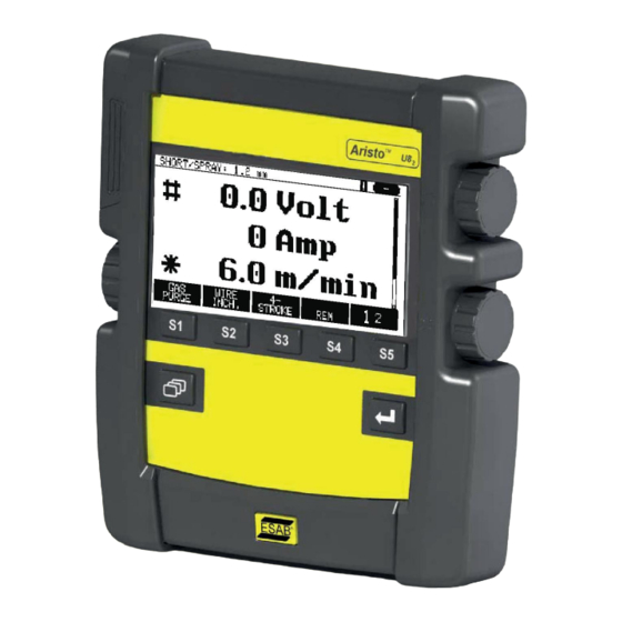
3.1.4 Measure SHORT/SPRAY. Fe, CO2, 1.2 mm 0.0 Volt In MEASURE, you can view measured values for various welding 0 Amp parameters while welding is in progress. 6.0 m/min WIRE PURGE INCH STROKE FUNCT You can change the value of certain parameters in the Measure screen. Which parameters these are depends on which welding process is set. -
Page 15: Fast Mode Menu
3.1.6 Fast mode menu SHORT/SPRAY. Fe, CO2, 1.2 mm 28.5 Volt In the FAST MODE menu, you can “link” soft keys to weld data 0 Amp memory positions. These settings are carried out in the 6.0 m/min Configuration menu. The number of the selected memory position is displayed in the top right corner. -
Page 16: Settings In The Weld Data Setting Menu
Settings in the weld data setting menu 4.1.1 MIG/MAG welding with short- - /sprayarc. Settings Setting range In steps of Synergy Adjust- depend- able in synergy Voltage 8 -- 60 V 0.25 V (displayed with one decimal) Wire feed speed** 0.8 -- 25.0 m/min 0.1 m/min Inductance... -
Page 17: Mig/Mag Welding With Pulsing
4.1.2 MIG/MAG welding with pulsing Settings Setting range In steps of Synergy Adjust- depend- able in synergy Voltage 10 -- 50 V 0.25 V (displayed with one decimal) Wire feed speed* 0.8 -- 25.0 m/min 0.1 m/min Pulse current** 100 -- 650 A Pulse time 1.7 -- 25.5 ms 0.1 ms... - Page 18 4.1.3 MIG/MAG welding with SuperPulse™, primary/secondary, short- -/sprayarc/pulsing Main menu → Process → Method → Phase → Method Settings Setting range In steps of Synergy Adjustable dependent in synergy Phase Primary or Secondary Method Short--/sprayarc or pulsing Voltage 10 -- 50 V 0,25 V(displayed with 1 decimal) Wire feed speed*...
-
Page 19: Mig/Mag Welding With Qset
4.1.4 MIG/MAG welding with QSet Main menu → Process → Method Settings Setting range In steps of QSet --18 -- +18 Wire feed speed* 0.8 -- 25.0 m/min 0.1 m/min Inductance 0 -- 100% Control type 1 -- 12 Gas pre--flow 0.1 -- 25 s 0.1 s Creep start... - Page 20 Pulse current The higher of the two current values in the event of pulsed current. Pulse current is set in the weld data setting menu with the synergy function switched off. Only applies to MIG/MAG welding with pulsing. Pulse time The time the pulse current is on during a pulse period.
- Page 21 For wire and gas combinations, see the tables on page NO TAG. It is possible to order different packages of synergic lines, although these must be installed by an authorised ESAB service engineer. For the creation of own synergic lines, see chapter 10.8 Activation of the synergy takes place in the weld data setting menu.
- Page 22 Gas pre- - flow This controls the time during which shielding gas flows before the arc is struck. Gas pre--flow is set in the weld data setting menu ! start data. Creep start Creep starting feeds out the wire at 50% of the set speed until it makes electrical contact with the workpiece.
- Page 23 In pulse welding mode, it is possible to choose between pulsed and non pulsed crater filling. Non pulsed crater filling is the faster process. Pulsed crater filling takes a little longer, yet gives spatter free crater filling when appropriate values are used. Synergy –...
-
Page 24: Superpulse
The setting is adjusted in the Configuration menu ! MIG/MAG defaults. Gas post- -flow This controls the time during which shielding gas flows after the arc is extinguished. Gas post--flow is set in the weld data setting menu ! stop data. Setting limits and measure limits In limits, a limit number is selected. -
Page 25: Wire And Gas Combinations
4.3.1 Wire and gas combinations For wire and gas combinations, see the tables on page NO TAG. 4.3.2 Different pulsing methods Below you can see which pulsing method can be used, depending on the plate thickness that is to be welded. Heat Spray in primary phase and pulsing in secondary phase... - Page 26 The graphs for 15 m/min and 20 m/min relate to primary wire feed speed. The cycle time is the sum of primary and secondary phase time. The difference between primary and secondary wire feed speed may not exceed the speed that is specified by the graphs for primary wire speed. Example: If the cycle time is 0.25 s and the primary wire feed speed is 15 m/min, the difference between primary and secondary wire feed speed may not exceed 6 m/min.
-
Page 27: Qset
QSet Main menu → Process → Method QSet is used to facilitate setting welding parameters. Using the plus/minus knobs, the arc length is increased or decreased from --18 to + 18 steps. SHORT ARC When first starting welding with a new wire type/gas type, QSet automatically sets all the necessary welding parameters. -
Page 28: Tig Welding
TIG WELDING Main menu → Process TIG welding TIG welding melts the metal of the workpiece, using an arc struck from a tungsten elec- trode, which does not melt itself. The weld pool and the electrode are protected by shielding gas. Pulsed current Pulsing is used for improved control of the weld pool and the solidification process. -
Page 29: Tig Welding With Pulsing Dc
6.1.2 TIG welding with pulsing DC Settings Setting range In steps of HF/LiftArct HF or LiftArc 2/4 stroke 2 stroke or 4 stroke Pulse current* 4 -- 500 A Background current 4 -- 500 A Pulse time 0.001 -- 5 s 0.001 s Background time 0.001 -- 5 s... - Page 30 2- -stroke Gas pre--flow Slope Slope down Gas post-- flow Functions when using 2 stroke control of the welding torch. In the 2 stroke control mode, pressing the TIG torch trigger switch (1) starts gas pre--flow (if used) and strikes the arc. The current rises to the set value (as controlled by the slope up function, if in operation).
- Page 31 Pulse current The higher of the two current values in the event of pulsed current. When pulsing, slope up and slope down are also pulsed. Pulse current is set in the weld data setting menu. Only applies to TIG welding with pulsing. Background current The lower of the two current values in the event of pulsed current.
-
Page 32: Other Function Explanations
Gas pre- - flow This controls the time during which shielding gas flows before the arc is struck. Gas pre--flow is set in the weld data setting menu. Gas post- -flow This controls the time during which shielding gas flows after the arc is extinguished. Gas post--flow is set in the weld data setting menu. -
Page 33: Arc Air Gouging
ARC AIR GOUGING Main menu → Process With arc air gouging, a special electrode comprising a carbon rod with a copper casing is used. An arc is formed between the carbon rod and the workpiece, which melts the material. Air is supplied so that the melted material is blown away. The following electrode diameters can be selected for arc air gouging: 4.0, 5.0, 6.0, 8.0, 10 and 13 mm. -
Page 34: Memory Management
MEMORY MANAGEMENT Control panel working method The control panel can be said to comprise two units: working memory and weld data memory. Store Working memory Welding data memory Recall In the working memory, a complete set of weld data settings is created that can be stored in the weld data memory. -
Page 35: Recall
WELD DATA MEMORY We are now going to store a set of weld data. It will be given memory position 5. Press STORE. STORE FUNCT QUIT WELD DATA MEMORY Select row five using 5 - - one of the knobs. Press STORE. - Page 36 WELD DATA MEMORY Select the row using 1 -- one of the knobs. Press 2 -- RECALL. 3 -- 4 -- 5 - - (TIG) 6 -- 7 -- TIG HF--START 100 AMP STORE RECALL DELETE FUNCT QUIT WELD DATA MEMORY Press YES to confirm 1 -- that you want to recall...
-
Page 37: Delete
Delete It is possible to delete one or more data sets in the memory menu. We are going to delete the data set we stored in an earlier example. WELD DATA MEMORY Select the data set. 1 -- Press DELETE. 2 -- 3 -- 4 --... -
Page 38: Copy
Copy To copy the content of a weld data set to a new memory position, proceed as follows: WELD DATA MEMORY Select the memory 1 -- position you want to 2 -- copy and press 2ND 3 -- FUNCT. 4 -- 5 - - (TIG) 6 -- 7 --... -
Page 39: Edit
WELD DATA MEMORY Press YES. 44-- 45 -- 46 -- 47 -- 48 -- 49 -- 50 - - COPY DATA SET 5 TO POSITION: 50 Weld data number 5 has now been copied to memory position 50. Return to the memory menu with QUIT. Edit To edit the content of a weld data set, proceed as follows: WELD DATA MEMORY... - Page 40 Select the setting you START METHOD HF- -START want to edit and press GUN TRIGGER MODE 4--STROKE ENTER. Select from the list and press ENTER again. TIG HF--START 100 AMP QUIT WELD DATA SETTING Press SET to move to CURRENT 100 A WELD DATA SETTING.
-
Page 41: Name
Name To give a stored weld data set its own name, proceed as follows: WELD DATA MEMORY Select the memory 1 -- position you want to 2 -- name and press 2ND 3 -- FUNCTION. Then 4 -- press EDIT. 5 - - (TIG) 6 -- 7 --... -
Page 42: Configuration Menu
CONFIGURATION MENU Main menu → Configuration menu This menu contains the following sub--menus: Language, see chapter “First step – choice of language” 2.4. Code lock, see chapter Remote control, see chapter MIG/MAG basic defaults, see chapter MMA basic defaults, see chapter Fast mode soft buttons, see chapter Double start sources, see chapter Panel remote enable, see chapter... -
Page 43: Lock Code Status
9.1.1 Lock code status In lock code status, you can activate/deactivate the lock function without deleting the existing lock code in the event you deactivate the function. If no lock code is stored and you try to activate the code lock, the keyboard is displayed for entering a new lock code. -
Page 44: Remote Controls
Remote controls Main menu → Configuration menu → Remote controls Non CAN--bus connected remote control units must be connected via a remote control adapter. The SuperPulse method is not supported by this function. After connection, activate the remote control unit in the measure screen with the soft key REMOTE. -
Page 45: Configuration For Analogue Remote Control Unit
9.2.3 Configuration for analogue remote control unit Without remote control adapter When connecting a CAN--based remote control unit, configuration of ANALOG 1 and ANALOG 2 takes place automatically. The configuration cannot be altered. With remote control adapter When you use an analogue remote control unit, you can specify on the control panel which (maximum 2) potentiometer(s) you want to use. -
Page 46: Mig/Mag Defaults
MIG/MAG defaults Main menu → Configuration menu → MIG/MAG defaults In this menu you can set: Gun trigger mode (2--stroke/4--stroke) 4--stroke configuration Soft key configuration Voltage measurement in pulsing AVC feeder “Release pulse” 9.3.1 Gun trigger mode (2- - stroke/4- - stroke) 2- - stroke Gas pre--flow Welding... -
Page 47: Stroke Configuration
4- -stroke There are 3 start and 2 stop positions for 4--stroke. This is start and stop position 1. When resetting, position 1 is selected. See the chapter 9.3.2 “4--stroke configuration”. Gas pre--flow Welding Crater Gas post--flow start filling. Functions when using 4- -stroke control of the welding gun Gas pre--flow starts when the welding gun trigger switch is pressed (1). -
Page 48: Soft Key Configuration
Trigger--controlled hot start Gas flow Wire feed Gas pre--flow Hot start Welding Press in the trigger switch (1); gas pre--flow starts and hot start runs until the switch is released (2). 4- - stroke stop setting Time--controlled crater filling with possible extension, see chapter 9.3.1 “4--stroke”... -
Page 49: Voltage Measurement In Pulsing
In the display screen there are two columns: one for function and one for key number SOFT KEYS SETUP Function Soft key NONE GAS PURGE WIRE INCHING TRIGGER MODE (2/4) CRATER FILL ON/OFF CREEP START ON/OFF HOT START ON/OFF TRIGGER SWITCH WIRE PURGE INCH... -
Page 50: Avc Feeder
9.3.5 AVC feeder When you have connected an AVC wire feed unit (ARC VOLTAGE CONTROL), go into the CONFIGURATION menu under MIG/MAG BASIC SETTINGS. Press ENTER at the AVC wire feed unit row and select ON. The equipment is then reconfigured automatically to match an AVC wire feed unit. -
Page 51: Double Start Sources
Then step down with the left--hand knob to the next row ASSOCIATED WELD DATA. Here you can browse through the weld data sets that are stored in the weld data memory. Select the desired weld data number using the plus/minus knobs. Press STORE to save. - Page 52 Activating weld data switch TRIGGER WELD DATA SWITCH Position the cursor on TRIGGER WELD DATA SWITCH the TRIGGER WELD ADD/DELETE WELD DATA DATA SWITCH row and press ENTER. Select SELECTED WELD DATA OFF, ARC OFF or ON. Press ENTER. MIG/MAG SHORT/SPRAY SYNERGIC MODE ON Fe, CO2, 1.2 mm + 3.5 VOLT, 7.6 M/MIN QUIT...
-
Page 53: Multiple Wire Feeders
9.10 Multiple wire feeders Main menu → Configuration menu → Multiple wire feeders When connecting several wire feed units (max. 4), you have to use wire feed units without a weld data unit, i.e. with an empty panel.. All wire feed units that are supplied to the customer have identity number 1. The first thing you have to do when connecting several wire feed units is to change the identity number (node address) of one wire feed unit. -
Page 54: Quality Functions
When the interval has been passed, fault code 54 is displayed in the error log. Reset by pressing the RESET soft key. When TOTAL RUNNING TIME LIMIT is selected instead of the number of starts, an authorised ESAB service technician is contacted. SERVICE CONTACT TIP CHANGE INTERVAL... -
Page 55: Unit Of Length
For information regarding these functions, see page 72. In order to get access to these functions you have to contact ESAB. When you indicate the serial number of the unit you will get a key code, which is to be entered in the menu REGISTER KEY. -
Page 56: Tools
TOOLS Main menu → Tools This menu contains the following sub--menus: Error log, see chapter 10.1. Export/Import, see chapter 10.2. File manager, see chapter 10.3. Edit setting limits, see chapter 10.4. Edit measurement value settings, see chapter 10.5. Production statistics, see chapter 10.6. Quality functions, see chapter 10.7. -
Page 57: Delete Error Message
The following information can be read in the error log menu: The error number of the error The date on which the error has occurred The time at which the error has occurred The unit in which the error has occurred The error’s error management code ERROR LOG Index... - Page 58 Error Description code 5 V power supply low The power supply voltage is too low. The current welding process is stopped and starting is prevented. Action:Turn off the mains power supply to reset the unit. If the error persists, send for a service technician.
- Page 59 Error Description code Transmitter buffer overflow The control panel does not manage to transmit information to the other units sufficiently quickly. Action: Turn off the mains power supply to reset the unit. Receiver buffer overflow The control panel does not manage to process information from the other units sufficiently quickly.
-
Page 60: Export/Import
10.2 Export/Import Main menu → Tools → Export/Import In the Export/Import menu, it is possible to transfer information to and from the control panel via a USB memory. The following information can be transferred: Weld data sets Export/Import System settings ”... -
Page 61: File Manager
10.3 File manager Main menu → Tools → File manager In file manager you can process information both in a USB memory (C:\). File manager makes it possible to delete and copy weld data and quality data manually. When the USB memory is inserted, the display shows the basic folder of the memory if no folder already has been choosen. -
Page 62: Delete A File/Folder
FILE MANAGER Select a folder or file and press ALT. WeldData NEW FOLDER ErrorLog.xml QData.xml ~Weldoffice.dat INFO UPDATE ALT. QUIT This list is displayed when you have pressed ALT. COPY PASTE DELETE RENAME NEW FOLDER 10.3.1 Delete a file/folder Select the file or folder that is to be deleted and press ALT. Select DELETE and press ENTER. -
Page 63: Copy And Paste Files
10.3.4 Copy and paste files Select the file that is to be copied and press ALT. Select COPY and press ENTER. COPY PASTE DELETE RENAME NEW FOLDER Position the cursor in the folder in which the copied file is to be located and press ALT. -
Page 64: Edit Setting Limits
10.4 Edit setting limits Main menu → Tool → Edit setting limits In this menu you set your own max. and min. values for various welding methods. The limits cannot be above or below the values for which the power source is dimensioned. -
Page 65: Edit Measure Limits
10.5 Edit measure limits Main menu → Tools → Edit measure limits In this menu you set your own measurement values for the various welding methods. There are 50 storage points. Select the row for an empty storage point and press ENTER. -
Page 66: Production Statistics
10.6 Production statistics Main menu → Tools → Production statistics The production statistics will keep track of the total arc time, the total amount of material and the number of welds since the most recent reset. They will also keep track of the arc time and the amount of material used in the most recent weld. -
Page 67: Quality Functions
10.7 Quality functions Main menu → Tools → Quality functions Quality functions keep track of various interesting weld data for individual welds. These functions are: Time of welding start. Duration of welding. Maximum, minimum and average current during welding. Maximum, minimum and average voltage during welding. Maximum, minimum and average output during welding. -
Page 68: User Defined Synergic Data
EXPORT/IMPORT Select QUALITY WELD DATA SETS FUNCTION LOG, press SYSTEM SETTINGS EXPORT. SETTING LIMITS MEASURE LIMITS ERROR LOG QUALITY FUNCTION LOG PRODUCTION STATISTICS SYNERGIC LINES BASIC SETTINGS EXPORT QUIT The entire set of quality data (information about the 100 most recent welds) that is stored in the control panel is now saved on the USB memory. -
Page 69: Specify Valid Wire/Gas Combination
Short- - /Sprayarc Bring up the main menu and select the MIG/MAG method SHORT/SPRAY. Key in the desired values for voltage and wire feed speed for the first co--ordinate. Bring up the MEMORY menu and store the first co--ordinate on any number. The four co--ordinates for a short--/sprayarc line can be saved as any numbers. -
Page 70: Create Your Own Wire/Gas Alternative
Select an alternative that is displayed in the list and press ENTER. Ss 18%Cr 8%Ni Ss duplex Al Mg Al Si Metal cored Fe Select in the same way for SHIELDING GAS and press ENTER. Ar 18%CO2 Ar2%O2 ArHeO2 Select in the same way for WIRE DIAMETER and 0.6 mm press ENTER. -
Page 71: Calendar
The control panel’s keyboard is used as follows: Position the cursor on the desired keyboard character using the left--hand knob and the arrow keys. Press ENTER. Enter a complete character string with a maximum of 16 characters in this way. Press DONE. -
Page 72: Menu Structure
Menu structure NO TAG72 MIG/MAG Process Method Phase -- Method Wire type Shielding gas Wire diameter Configuration Tools Short/Spray Pulse Superpulse Qset Voltage Voltage QSet Wire speed Wire speed Wire speed Voltage Stop data Inductance Pulse current Inductance Wire speed -- crater fill Control type Pulse time... - Page 73 Process Method Electrode type Electrode diameter Configuration Tools * Not imple- mented yet MMA DC MMA AC * Current Current Arc Force Arc force Min current factor Min current factor Control type Control type Synergic mode Synergic mode Hot start Hot start Setting limits -- hot start duration...
- Page 74 Process Method Start method Gun trigger mode Configuration Tools * Not imple- mented yet Constant I Pulsed I Constant Pulsed AC* Current Current Current Current Slope up time Background current Slope up time Slope up time Slope down time Pulse time Slope down time Slope down time Gas preflow...
- Page 75 GOUGING Process Electrode diameter Configuration Tools Voltage Synergic mode Inductance Control type Edit description Edition 090515 - - 75 - -...
- Page 76 CONFIGURATION - - TOOLS MIG/MAG Process Method Wire Type GOUGING Shielding Gas Wire diameter Configuration Tools Configuration Tools Language Trigger welddata switch Error log Code lock Multiple wire feeders Export/import Remote controls Quality functions --weld data sets MIG/MAG defaults Maintenance --system settings --gun trigger mode Unit of length...
- Page 77 Functional differences NO TAG Functions Basic Plus Super Pulse Limit editor File manager Auto save mode Release pulse Synergic lines Basic package = 92 lines Complete no of available lines User defined synergic data Production statistics Edition 090515 - - 77 - -...
-
Page 78: Wire And Gas Dimensions
Wire and gas dimensions Basic - - MIG/MAG welding with SHORT- -/SPRAYARC Wire type Shielding gas Wire diameter (mm) Low alloy or unalloyed wire 0.8 1.0 1.2 1.6* (Fe) Ar + 18% CO 0.8 1.0 1.2 1.6* Ar + 8% CO 0.8 1.0 1.2 1.6* Ar + 23% CO 0.8 1.0 1.2 1.6*... - Page 79 Plus - - MIG/MAG welding with SHORT- - /SPRAYARC Wire type Shielding gas Wire diameter (mm) Low alloy or unalloyed wire 0.8 0.9 1.0 1.2 1.6* (Fe) Ar + 18% CO 0.8 0.9 1.0 1.2 1.6* Ar + 2% O 0.8 0.9 1.0 1.2 1.6* Ar + 5%O + 5% CO...
- Page 80 Plus - - MIG/MAG welding with PULSE Wire type Shielding gas Wire diameter (mm) Low alloy or unalloyed wire Ar + 18% CO 0.8 0.9 1.0 1.2 1.6* (Fe) Ar + 2% O 0.8 0.9 1.0 1.2 1.6* Ar + 2% CO 0.8 1.0 1.2 1.
-
Page 81: Ordering Number
0460 896 092 Instruction manual LT 0460 896 027 Instruction manual RU, GB 0459 839 037 Spare parts list For functional differences, see page 77 The instruction manuals are available on the Internet at www.esab.com. Edition 090515 - - 81 - -... -
Page 82: Accessories
Accessories Extension cable (connectors included) 7.5 m 12--poles ......0460 877 891 Adapter set 230 V AC / 12 V DC, for control 0457 043 880 box . - Page 83 - - 83 - -...
- Page 84 ESAB subsidiaries and representative offices Europe Asia/Pacific Representative offices NORWAY AS ESAB AUSTRIA BULGARIA CHINA Larvik ESAB Ges.m.b.H ESAB Representative Office Shanghai ESAB A/P Tel: +47 33 12 10 00 Vienna- -Liesing Sofia Shanghai Fax: +47 33 11 52 03...
Need help?
Do you have a question about the Aristo U82 and is the answer not in the manual?
Questions and answers