Table of Contents
Advertisement
Advertisement
Table of Contents

Related Manuals for ESAB GMH


Summary of Contents for ESAB GMH
- Page 1 Bruksanvisning Manuel d’instructions Brugsanvisning Gebruiksaanwijzing Bruksanvisning Instrucciones de uso Käyttöohjeet Istruzioni per l’uso Instruction manual Manual de instruções Betriebsanweisung 使用说明书 0460 671 160 2012- -04- -16 Valid for serial no. 936- -xxx- -xxxx, 049- -xxx- -xxxx...
- Page 2 SVENSKA ..........DANSK .
- Page 3 Type designation etc. Typbeteckning etc. GMH, from serial number 936 xxx xxxx (2009 w.36) GMH is designed to be used with ESAB welding equipment Manufacturer or his authorised representative established within the EEA Name, address, telephone No, telefax No: Tillverkarens namn, adress, telefon, telefax: ESAB AB, Welding Equipment Esabvägen, SE- - 695 81 LAXÅ, Sweden...
-
Page 4: Table Of Contents
ENGLISH 1 SAFETY ............2 INTRODUCTION . -
Page 5: Safety
Responsibility for the safety and function of the final operation lies with the Integra- tor. Users of ESAB welding equipment have the ultimate responsibility for ensuring that anyone who works on or near the equipment observes all the relevant safety precautions. Safety precautions must meet the requirements that apply to this type of welding equipment. - Page 6 WARNING ARC WELDING AND CUTTING CAN BE INJURIOUS TO YOURSELF AND OTHERS. TAKE PRECAU- TIONS WHEN WELDING. ASK FOR YOUR EMPLOYER’S SAFETY PRACTICES WHICH SHOULD BE BASED ON MANUFACTURERS’ HAZARD DATA. ELECTRIC SHOCK - - Can kill Install and earth the welding unit in accordance with applicable standards. Do not touch live electrical parts or electrodes with bare skin, wet gloves or wet clothing.
-
Page 7: Introduction
GMH is joint--tracking equipment for the positioning and joint--tracking of automatic welding equipment in all types of joint that arise where the sensor finger has a guiding edge to follow. The equipment is adapted to ESAB’s standard servo slides and control one or two servo motors simultaneously. -
Page 8: Technical Data
Technical data Supply voltage 42V AC, 50--60 Hz Current output 450 V A Ambient temperature --15 C -- + 45 C Relative atmospheric humidity Max. 98% Max. motor current 6A 100% Enclosure class IP 23 Current limits 15 A (hardware current limit) Power supply fusing 10 A slow Motor regulator, type... -
Page 9: Main Parts
Main parts 1. Joint--tracking unit (with or without control panel) 2. Portable control box 3. Sensor 4. Slide cross for sensor 5. Guide finger 6. Control cable (2 m) 7. Motor cable (see Accessories) The portable control box (2) and the control cable (6), in accordance with the above, are discontinued for certain columns and booms and are replaced by product specific parts. - Page 10 2.4.1 Sensor The sensor is shaped like a finger. The finger is spring--loaded so that it attempts to reach the centre position laterally and downwards vertically. 1. Sensor with connection for cable to joint--tracking unit and with bracket for different tracking fingers at the front. 2.
-
Page 11: Installation
4. Fit the guide finger parallel with the motor driven slide cross. Tuning the sensor finger Please refer to ESAB’s service department for tuning the sensor finger. Tuning the inductive sensor Please refer to ESAB’s service department for tuning the inductive sensor. -
Page 12: Operation
OPERATION General General safety regulations for the handling of the equipment can be found on page 85. Read through before you start using the equipment! Joint- -tracking unit with control panel Emergency stop (1) One press on the button activates EMERGENCY STOP NB! An emergency stop must never be reset before the cause of the abnormal function or signal has been established and rectified. - Page 13 Switch with 5 positions Selection of joint--tracking and joint--searching options: Manual preset -- Position Vertical and horizontal joint--tracking -- Position Vertical and horizontal joint--tracking with joint--searching to the right -- Position Vertical and horizontal joint--tracking with joint--searching to the left -- Position Vertical joint--tracking -- Position NOTE! If the switch is in a joint--tracking position when the equipment is switched on then...
-
Page 14: Joint--Tracking Unit -- Rear Section
Joint- -tracking unit - - rear section Connection, power supply 42 V Switch Power supply On/Off Switch For switching the horizontal slide motor’s direction of movement. Socket, for connecting the vertical slide motor Socket, for connecting the horizontal slide motor Control fuse, 10 A slow Sleeve socket (8--pin), for connecting the guide finger. -
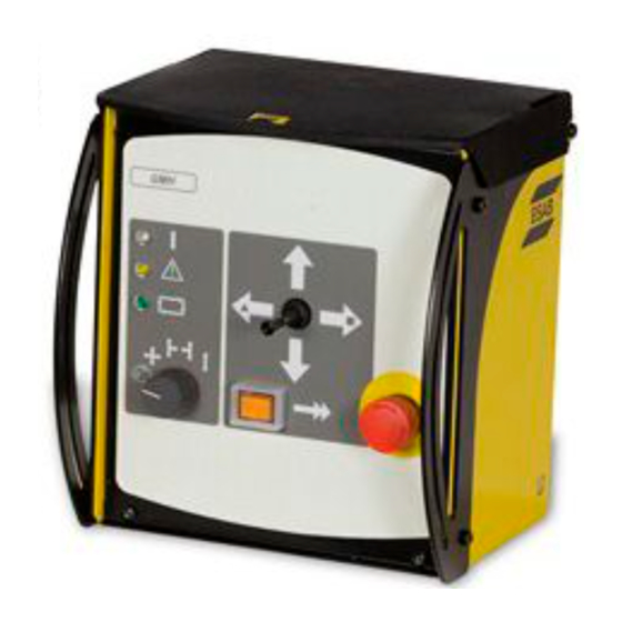
Page 15: Portable Control Box
Portable control box Emergency stop (1) One press on the button activates EMERGENCY STOP NB! An emergency stop must never be reset before the cause of the abnormal function or signal has been established and rectified. Signal lamp (white) Illuminates when the power has been switched on. Alarm lamp (automatic joint- tracking) (yellow) Illuminates when the guide finger is outside the working range (vertical). - Page 16 Switch with 5 positions Selection of joint--tracking and joint--searching options: Manual preset -- Position Vertical and horizontal joint--tracking -- Position Vertical and horizontal joint--tracking with joint--searching to the right -- Position Vertical and horizontal joint--tracking with joint--searching to the left -- Position Vertical joint--tracking -- Position NOTE! If the switch is in a joint--tracking position when the equipment is switched on then...
-
Page 17: Joint--Tracking
Joint- -tracking The joint--tracking equipment can be set for different types of joint--tracking. It can be set for joint--tracking with edge control and for joint--tracking with groove control. The setting is made both on the control box and on the sensor. 4.5.1 Joint- - tracking with edge control The following functions are set on the control box,... - Page 18 Examples of different types of joint and of the guide finger’s application against the guiding edges. Joint type Setting, con- trol box Double flanged butt weld I--weld (A=guide bar) V--weld 1/2 V--weld 1/2 V--weld U--weld Double U--weld J--weld Double J--weld - - 98 - - hga1o1ea...
- Page 19 X--weld Asymmetrical X--weld K--weld K--weld Fillet weld - - 99 - - hga1o1ea...
-
Page 20: Positioning For Welding Start
Positioning for welding start 1. Align the welding equipment into position in relation to the weld joint so that the working range of the slide cross covers the whole height and lateral deviation of the joint from starting point to the stopping point for welding. 2. - Page 21 Positioning for welding start (with inductive joint- -tracking) The product must be configured before inductive joint--tracking is possible. Please refer to ESAB’s service department for configuration. 1. Align the welding equipment into position in relation to the weld joint so that the working range of the slide cross covers the whole height and lateral deviation of the joint from starting point to the stopping point for welding.
-
Page 22: Maintenance
Part no. 146 586--001 ORDERING OF SPARE PARTS Spare parts are ordered through your nearest ESAB representative, see back cover. When ordering spare parts, please state machine type and number as well as desig- nation and spare part number as shown in the spare parts list on page 251. -
Page 23: Accessories
-- 4000 rpm ratio 74:1 Motor cable 0460745xxx The cable is available in different lengths, see the appropriate sales brochure for the servo slide (contact ESAB’s sales office) Finger with ball (L=100 mm) 0416719001 Finger for internal and external corner... - Page 24 SCHEMA SKEMA SKJEMA JOHDOTUSKAAVIO DIAGRAM SCHALT- PLAN SCHÉMA SCHEMA ESQUEMA SCHEMA ESQUEMA GMH with control panel - - 244 - - schema...
- Page 25 GMH with portable control box - - 245 - - schema...
- Page 26 GMH, Portable control box - - 246 - - schema...
- Page 27 MÅTTSKISS MÅLSKITSE MÅLSKISSE MITTAPIIRUSTUS DIMENSION DRAWING MASSBILD COTES D’ENCOMBREMENT MAATSCHETS CRO- QUIS ACOTADO DIMENSIONI ESBOÇO COM DIMENSÕES - - 247 - - mskiss...
- Page 28 - - 248 - - mskiss...
- Page 29 - - 249 - - mskiss...
- Page 30 - - 250 - - sida...
- Page 31 Joint tracking unit without control panel 0460503881 GMH with MMC Complete Joint tracking unit with control panel 0460698880 GMH with portable control box Joint tracking unit without control panel and with portable control box 0460570880 Portable control box 0416688880 Sensor...
- Page 32 Item Ordering no. Denomination Notes 0460503880 Without control panel 0460468880 Basic module Outlet module, GMH portable control See separate part page 236 0460462880 MMC without controls 0194292020 Grommet Ø20 Screw MRT, ground- -cutter (black) M5x12 Screw MRT (black) M5x16 0460673880...
- Page 33 Item Ordering no. Denomination Notes 0460503881 GMH with MMC With control panel 0460468880 Basic module Outlet module, GMH MMC See separate part page 236 0460462882 MMC GMH 0194292020 Grommet Ø20 Screw MRT, ground- -cutter (black) M5x12 Screw MRT (black) M5x16...
- Page 34 Item Ordering no. Denomination Notes 0460468880 Basic module 0458679885 Operating contact can tractor Screw RX- -PT 6- -19x8 Screw MRT ground- -cutter M5x12 Screw MRT M4x8, DIN 7985 0460465001 Spacer for hinge 0460463001 Protective frame 0460430001 Cover 0460469001 Sun visor Screw MRT (black) M5x16 Circuit board module...
- Page 35 0460461001 Heat sink 0487528881 PC board, motor drive 0487522981 PC board, motor control 0487522982 PC board, motor control GMH with inductive sensor 0460648880 Cable set with rectifier bridge Spring washer 0193700703 Ribbon cable+connectors 26- -pole - - 255 - -...
- Page 36 Item Ordering no. Denomination Notes Outlet module, GMH portable control box Screw MRT ground- -cutter M5x12 Flat pin 6,3x0,8 M6 Screw RTS st2,9x13 Screw RX- -PT 6- -19x8 0193701001 Fuse holder fine.5x12 0193701002 Fuse holder 5x20 0567900116 Fuse 10 A (Slow)
- Page 37 LED (white) 24 V 0194282002 LED (yellow) 24 V 0194282003 LED (green) 24 V 0460600328 Knob, grey with arrow d28- -6mm Cable set GMH with MMC 0415200020 Contact block 1no+1nc 1no+1nc 0415200027 Cap orange 18x24 0415200001 Push- -button 18x24 0415200047...
- Page 38 Item Ordering no. Denomination Notes 0460698880 GMH with portable control box 0460503880 GMH without MMC 0460570880 Portable control box 0460481001 Bracket Screw (Black) MRT M5x16 - - 258 - - h460698s...
- Page 39 Item Ordering no. Denomination Notes 0460570880 Portable control box 0194282001 LED indicator white 0194282002 LED indicator yellow 24 V 0194282003 LED indicator green 24 V 0460424881 Emergency stop complete 0460795001 Joy- -stick 0194055009 Switch 5 settings 0460569001 Cover 0460600328 Knob, grey with arrow d28- -6mm 0460759880 Remote cable...
- Page 40 Item Ordering no. Denomination Notes 0460759880 Remote cable 0193963002 Cable screened 6x1,5mm2 12x0,5mm2 0193307105 Cable fitting stp- -b 16 0194200023 Cable gland with tube 23- -pole 0194182023 Pin plug 23- -pole 0323945001 Connector pin rm20m- -13k 0323945004 Connector pin rm16m- -23k - - 260 - - h460759s...
- Page 41 Item Ordering no. Denomination Notes 0416688880 Sensor 0156106880 Joint tracking sensor 0415836880 Diffusor 0415739001 Insulation t 0,125 0417258880 Sleeve 0416671001 Guide arm 0415328001 Yoke 0211101049 d3x18 0193860109 Pressure pin reinforced m8x16 0417958880 Ring with adjustable screw 0415329001 Guide arm attachment 0146586001 Guide finger 0415332002...
- Page 42 Item Ordering no. Denomination Notes 0416739880 Slide cross for sensor 0413366112 Clamp 0193570120 Locking lever m6x50x63 0193570109 Locking lever m6x16x45 0433851001 Mini slide 0413366115 Clamp 0193570150 Locking lever m6x75 0413366320 Clamp 0417096880 Mounting bracket 0417097001 Clamp 0417098880 Mounting bracket 0417099880 Plate 0417097002 Clamp...
- Page 43 Item Ordering no. Denomination Notes 0821425880 Slide cross for sensor+laser lamp 0413366112 Clamp 0193570120 Locking arm adjustable 0193570109 Locking arm adjustable 0433851001 Mini slide 0413366115 Clamp 70x58x30 d35 0193570150 Locking arm adjustable m6x75 0417096880 Mounting bracket 0417098880 Angle bracket 0417099880 Plate for slide cross 0821423001 Clamp...
- Page 44 ESAB Romania Trading SRL ESAB VAMBERK s.r.o. SOUTH AFRICA ESAB Mexico S.A. Bucharest Vamberk ESAB Africa Welding & Cutting Ltd Monterrey Tel: +40 316 900 600 Tel: +420 2 819 40 885 Durbanvill 7570 - Cape Town Tel: +52 8 350 5959...
Need help?
Do you have a question about the GMH and is the answer not in the manual?
Questions and answers