
Subscribe to Our Youtube Channel
Related Manuals for GEA Hilge CONTRA I ADAPTA


Summary of Contents for GEA Hilge CONTRA I ADAPTA
- Page 1 Hygienic Pumps GEA Hilge CONTRA I/II ADAPTA Operating instruction (Translation from the original language) BA.10A.ADY.001.GB_1...
- Page 2 (print, photocopy, microfilm or another method) without the prior written permission of GEA Hilge Office of GEA Tuchenhagen GmbH hereinafter referred to as Manufacturer in any form (print, photocopy, microfilm or other process) reproduced or distributed. This restriction also applies to the drawings and diagrams included in the documentation.
- Page 3 These instructions were written to the best of our conscience. However, the manufacturer is not liable for any errors that may be contained in this document or for any resulting consequences. The manufacturer reserves the right to make technical changes by further development of the pump described in these instructions.
- Page 4 LAYOUT INFORMATION Bullet points and numbered list characters Bullet points are used to separate logical contents within a section: • Bullet point 1 Types of bullet point 1. • Bullet point 2 Types of bullet point 2. Numbered list characters are used to separate enumerations within a descriptive text: Descriptive text with consecutive numbering: –...
-
Page 5: Table Of Contents
TABLE OF CONTENTS General Information about this document Manufacturer address Customer Service EU Declaration of Conformity for Machines Safety Intended use 2.1.1 Pumped fluids 2.1.2 Minimum flow rate Minimum flow rates in explosive atmospheres 2.1.3 Connections and piping 2.1.4 Switching frequency 2.1.5 Types Safety precautions in these operating instructions... - Page 6 10.3 Malfunctions and remedies 10.4 Repair 10.4.1 Repair order 10.4.2 GEA Hilge assembly tool kit Contents and use 10.4.3 Parts overview 10.4.4 Parts overview of ADAPTA bearing housing sizes 1 and 2 10.4.5 Parts overview ADAPTA bearing housing size 3 10.4.6...
- Page 7 11.2 Safety instructions 11.3 Temporary decommissioning 11.4 Disposal Appendix 12.1 Clearance certificate BA.10A.ADY.001.GB_1 20.07.2018...
- Page 8 BA.10A.ADY.001.GB_1 20.07.2018...
-
Page 9: General
Versions, technical data and spare part numbers are subject to technical change. We reserve the right to implement changes due to technical progress. Manufacturer address GEA Hilge Niederlassung der GEA Tuchenhagen GmbH Hilgestraße 37-47 55294 Bodenheim Germany Phone +49 6135 7016-0 Fax +49 6135 1737 hilge@gea.com... -
Page 10: Eu Declaration Of Conformity For Machines
EU Declaration of Conformity for Machines in accordance with the EC Machinery Directive 2006/42/EC, Annex II 1. A Manufacturer: GEA HILGE Office of GEA Tuchenhagen GmbH Hilgestrasse 37-47 D 55294 Bodenheim Germany We declare under our sole responsibility that the machine... -
Page 11: Safety
Safety Intended use Safety Intended use Warning! Non-intended use! ► Pump only media that are specified in the order. The pump has been specially designed for them. ► Operate the pump only on the electrical grid that was specified in the purchase order. - Page 12 Safety Safety precautions in these operating instructions These operating instructions contain basic precautions that must be observed during installation, operation and maintenance. They must therefore be read by the installer and relevant personnel or operator prior to installation and commissioning. The operating instructions must always be available at machine/ system site.
-
Page 13: Explanation Of The Safety Symbols Used
Safety Explanation of the safety symbols used Explanation of the safety symbols used Danger Stands for an immediate danger which leads to heavy physical injuries or to the death. ► Description to avert the danger Warning! Stands for a possibly dangerous situation which leads to heavy physical injuries or to the death. -
Page 14: Dangers Of Non-Compliance With Safety Information
Safety Unauthorised modification and ordering of spare parts Warning! Hazardous materials Contact with dangerous substances, e.g. by inhalation. ► Discharge the leakage of dangerous goods such that no danger to persons and the environment arises! ► Comply with legal provisions! ►... -
Page 15: Staff Qualifications And Training
Safety Staff qualifications and training Staff qualifications and training The staff for working on and with the pump must have the appropriate qualifications. Responsibilities, competencies and supervision of staff must be clearly defined by the operating company. If personnel do not have the necessary knowledge, they are to be trained and instructed. - Page 16 Safety – failure of the control circuit or control loop – incorrect assembly – fracture during operation – operating media or objects getting thrown out – loss of stability – personnel slipping, tripping or falling BA.10A.ADY.001.GB_1 20.07.2018...
-
Page 17: Description
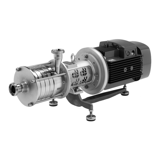
Description Pump overview Description Pump overview 0680 0180 A 0181 0801 0156 0107 0153 0330 0180 B Fig.1 0107 - Discharge casing 0153 - Suction port 0156 - Discharge port 0180 A - Foot (combi foot) 0180 B - Foot (cast iron foot) 0181 - Pump stand (vertical stand) 0330 - Bearing housing 0680 - Shroud... -
Page 18: Standard Version Applications
Number of Pump name Design type Nominal width of stages poles [kW] Type plate GEA Hilge Niederlassung der GEA Tuchenhagen GmbH Hilgestrasse - D - 55294 Bodenheim Pump-Type: Ser.-No.: TAG No.: YOM: Made in Germany Fig.2: Type plate GEA Hilge BA.10A.ADY.001.GB_1... - Page 19 Description Pump type: Pump name P: Motor rating Serial No.: Serial number n: Speed Q: Flow rate TAG No.:customer name H: Delivery head YOM: Year of manufacture Note: The type plate may differ from the presented layout. BA.10A.ADY.001.GB_1 20.07.2018...
-
Page 20: Transport And Storage
Transport and Storage Special personnel qualification for transport and storage Transport and Storage Special personnel qualification for transport and storage Transports may only be carried out by qualified staff, who must observe the safety instructions. Safety precautions for transport and storage Safety instructions for transporting the pump Warning! Falling loads... -
Page 21: Dimensions / Weights
Transport and Storage Dimensions / weights • After a longer storage period (more than 6 months), all elastomers (O-rings, shaft seals) must be checked for their elasticity. Brittle elastomers must be replaced. • Protect the pump from cold, moisture and dust, as well as from mechanical influences. -
Page 22: Unpacking The Pump
Transport and Storage Unpacking the pump Weight [kg] CONTRA II ADAPTA Stages Motor output [kW] Motor size Weight 15.0 160L 160.0 132S 130.0 11.0 160M 155.0 15.0 160L 162.5 18.5 160L 184.0 11.0 160M 157.5 15.0 160L 165.0 18.5 160L 186.5 22.0 180M... -
Page 23: Technical Data
Technical data Serial number Technical data The operating safety of the delivered machine is only guaranteed if the machine is used as intended according to the sections of the operating instructions and the purchase order. Warning! Overload of the pump! ►... -
Page 24: Maximum Operating Temperatures
Technical data Maximum operating temperatures Noise emissions L [dB (A)] - CONTRA I, 4-pole Motor rating 1-stage 2-stage 3-stage 4-stage 5-stage 6-stage [kW] Noise emissions L [dB (A)] - CONTRA II, 2-pole Motor rating 2-stage 3-stage 4-stage 5-stage [kW] 15.0 18.5 22.0 Noise emissions L... -
Page 25: Resistance Of Sealing Materials
Technical data Resistance of Sealing Materials • Type of connections • Type of mechanical seal. Resistance of Sealing Materials The resistance of sealing materials depends on the type and temperature of the medium conveyed. The exposure time can adversely affect the service life of the seals. -
Page 26: Assembly And Installation
Assembly and installation Safety precautions for setup, installation, and connection Assembly and installation Safety precautions for setup, installation, and connection Warning! Tipping (tilting) of the pump! ► The surface for setting up the pump should be clean, level and have sufficient load-bearing capacity. - Page 27 Assembly and installation Safety precautions for setup, installation, and connection Warning! Overheating! ► Ensure adequate ventilation. ► Avoid sucking in the heated exhaust air also of adjacent units. ► Maintain minimum distances. Caution! Vibration! ► Ensure stable construction for mounting of the pump and piping. Insufficiently stiffened substructures may cause an overall structure capable of oscillating, which is excited to oscillate by hydraulic and/or motor forces during changing operating conditions in the system.
-
Page 28: Mechanical Seals In Tandem Arrangement
Assembly and installation Special personnel qualification 6.1.1 Mechanical seals in tandem arrangement Caution! Missing supply of flushing fluid! Dry running of the mechanical seal. ► Always connect the flushing lines such that supply for flushing is always ensured. ► Ensure that flushing fluid is supplied even when checking the motor’s direction of rotation. -
Page 29: Checking Smooth Running Of The Impeller
Assembly and installation Setup, installation, and connection 6.3.1 Checking smooth running of the impeller Before installation, check that the impeller is running smoothly. Perform the following steps: Remove the motor shroud (only for SUPER version). Remove the motor fan cover. Note the pump’s direction of rotation (arrow). -
Page 30: Installation In The Piping System
Assembly and installation Setup, installation, and connection 6.3.3 Installation in the piping system Fig.5: Installation in the piping system top: Inlet operation | bottom: Suction operation | P - Pump | M - Motor 6.3.3.1 Space requirements Maintain the following minimum distances. Pay attention to motor performance. -
Page 31: Noise And Vibration Damping
Assembly and installation Setup, installation, and connection Vertical installation 5. 5 k W 0.55 - 4 kW Fig.7: Minimum distances in vertical installation 6.3.3.2 Noise and vibration damping To achieve optimum performance and to minimize noise and vibration, it is recommended to provide the pump with vibration dampers. - Page 32 Assembly and installation Setup, installation, and connection If the pump is mounted on a foundation along with vibration dampers, be sure to install compensators at the pipe connections. This prevents the pump from “hanging” in the connections. Compensators are installed to •...
-
Page 33: Using The Mechanical Seal
Assembly and installation Setup, installation, and connection Acoustic decoupling Fig.8: Example of a foundation of a pump A - compensators | B - solid base | C - Vibration damper 6.3.4 Using the mechanical seal For perfect operation, mechanical seals require a lubrication film in the sealing gap, which prevents contact between the two sliding surfaces. -
Page 34: Flush Connections For Double Mechanical Seals (Optional)
Assembly and installation Setup, installation, and connection 6.3.5 Flush connections for double mechanical seals (optional) 6.3.5.1 Flushing fluid (optional) Requirements of the flushing fluid The flushing fluid has the task to lubricate and cool the product-side mechanical seal and the radial packing ring on the atmospheric side. The flushing fluid must meet the following criteria: •... - Page 35 Assembly and installation Setup, installation, and connection Connecting the flushing Connect the inlet line (A). Note position of the lines depending on the direction of rotation. Connect the outlet line (B). Check correct fit of the connections. → The flushing has been connected. Double mechanical seal - back-to-back arrangement (optional) Sealing fluid To maintain their function, mechanical seals need a sealing fluid, which has the...
- Page 36 Assembly and installation Setup, installation, and connection • Protection against dry running • Lubrication and cooling of the mechanical seals A clean liquid, compatible with the pumped fluid, is used as the flushing medium. Ensuring the flushing operation Open the inlet of flushing fluid. Vent the seal cartridge.
-
Page 37: Electrical Connection
Assembly and installation Setup, installation, and connection Fig.11: Leakage outflow (A) 6.3.6 Electrical connection 6.3.6.1 Star connection Star connection for high voltage. Connect the pump according to the ordering information. The following figure shows the wiring diagram of the star connection. Fig.12: Star connection 6.3.6.2 Delta connection... -
Page 38: Checking The Direction Of Rotation After Connecting
Assembly and installation Setup, installation, and connection Large motors driven by a frequency converter are loaded by bearing currents. For pump motors that are used with an external frequency converter, HILGE recommends the use of insulated motor bearings for sizes of 37 kW and above to avoid increased wear of the motor bearings by possible bearing currents. -
Page 39: Earthing
Assembly and installation 6.3.6.5 Earthing Warning! Electrical voltage by different potentials. The occurrence of potential differences can cause damage to persons and property. ► Properly earth the pump and motor to achieve potential equalisation. Earthing the motor Equipotential bonding for the motor is performed via the protective conductor connection in the terminal box. -
Page 40: Commissioning
Commissioning Special personnel qualification Commissioning Special personnel qualification The commissioning personnel must be suitably qualified for this work. See also Section 2.6, Page 15. Safety instructions for commissioning Caution! Hazard due to overheating and pressure overload! ► Never pump for longer than 30 seconds against a closed shut-off device. Pumping against a closed shut-off device leads to rapid warming of the pumped fluid and pressure increase. -
Page 41: Vent Pump
Commissioning Commissioning / initial startup 7.3.2 Vent pump Notice Dry running of the mechanical seal Pumps that have not been fully vented will destroy the mechanical seal. ► Vent pump correctly as described and place in operation. Fig.14: Vertically installed pump A - Suction pipeline | B - Discharge valve in the pressure pipeline Perform the following steps: Open discharge valve (B) in the pressure pipeline. -
Page 42: Functional Testing Of The Mechanical Seal
Commissioning Ensure that the pipe system provided by the customer is cleaned. For double mechanical seal in back-to-back arrangement, connect the sealing fluid. Start flushing to prevent dry running. Open stop valves in the system. Fill the pump along with the system. Vent the pump along with the system. -
Page 43: Cleaning
Cleaning Special personnel qualification Cleaning To ensure the quality of sensitive fluids, pumps must be cleaned immediately after each use. Only in this way will adhesions and deposits be removed completely and contamination of the products be prevented. To achieve the best possible results, Hilge pumps are optimised with regard to gap and dead spaces, designed according to DIN EN 13951, and resistant to the cleaning agents referred to in the following chapter. -
Page 44: Cip
Cleaning Warning! Pressure shock by evaporating liquid! ► Completely empty the system before steam sterilisation. Notice Disposal of cleaning agents ► Dispose of cleaning agents properly and in an environmentally friendly way. CIP stands for Cleaning in Place, the pump is completely rinsed with cleaning agents. -
Page 45: Sip
Cleaning SIP stands for sterilisation in place, in which the pump is sterilised with superheated steam. For steam sterilization or sanitization, minimum temperatures of 121 ° C (250 ° F) must be applied to all wetted surfaces. The maximum permissible temperatures can be obtained from the section technical data. -
Page 46: Maintenance / Servicing
Inspections The pump is maintenance-free for the most part. In order to prevent possible malfunctions, GEA recommends that regular visual inspections be carried out. Special attention should be paid to the leak tightness and the correct functioning of the pump. -
Page 47: Maintenance Intervals
Maintenance / servicing Maintenance of the ADAPTA bearing – The O-ring has cracks. – The surface of the O-ring is porous and brittle. – The O-ring has lost its elasticity. 9.3.2 Maintenance intervals To ensure the highest operational reliability, all wearing parts should be replaced at longer intervals. -
Page 48: Bearing Housing Design Size 3
Maintenance / servicing Maintenance of the ADAPTA bearing 9.4.2 Bearing housing design size 3 The bearing consists of two angular contact ball bearings 0326.00 and one cylindrical roller bearing 0327.00. The two single row angular contact ball bearings make up the bearing structure on the motor-side. They are paired and are installed as fixed bearings in an X-arrangement to accommodate axial and radial forces from all directions. -
Page 49: Grease Filling
Maintenance / servicing Maintenance of the ADAPTA bearing 9.4.5 Grease filling In the factory, the cavities between the rolling elements are completely filled with grease. The grease is encapsulated by the V rings (0507.02) and (0507.05) and is designed as grease filling for normal environmental conditions. Refer to the following chapters for the grease quantities during installation. -
Page 50: Maintenance Of The Motor
Maintenance / servicing Maintenance of the motor Maintenance of the motor Motors without grease nipple Motors without grease nipple are equipped with lifetime lubrication. The grease life then depends on the bearing life. Prerequisite is that the motor must be used according to the specifications in the catalogue. -
Page 51: Malfunctions / Repairs
Malfunctions / repairs Special personnel qualification Malfunctions / repairs 10.1 Special personnel qualification The troubleshooting / repair personnel must be suitably qualified for this work. See also Section 2.6, Page 15. 10.2 Safety instructions Warning! Improper execution of work! ► Repair work should be carried out by authorised and qualified personnel. Danger Electric shock by touching live parts! ►... -
Page 52: Malfunctions And Remedies
Malfunctions / repairs Malfunctions and remedies Caution! Unsuitable tools! ► Make sure that all the parts can be mounted without damage. ► Use GEA Hilge assembly tools. 10.3 Malfunctions and remedies Actions for troubleshooting Malfunction Cause Remedy Pump does not Incorrect electrical connection (2 phases). -
Page 53: Repair
Malfunctions / repairs Repair Actions for troubleshooting Malfunction Cause Remedy Leakage at the Pump is strained (causing leaks at the pump body Install pump without strain, support piping by fixed pump body, or at the connections). points. connections, mechanical seal, Housing seals and connection seals defective. - Page 54 Malfunctions / repairs Repair If, despite careful emptying and cleaning of the pump, safety precautions are required, the necessary information must be given. BA.10A.ADY.001.GB_1 20.07.2018...
-
Page 55: Gea Hilge Assembly Tool Kit
Malfunctions / repairs Repair 10.4.2 GEA Hilge assembly tool kit Tools from the GEA Hilge assembly tool kit prevent damage to the mechanical seal during assembly. Fig.16: GEA Hilge assembly tool kit 10.4.2.1 Contents and use Tools in the GEA Hilge assembly tool kit... -
Page 56: Parts Overview
Malfunctions / repairs Repair 10.4.3 Parts overview 0230.01 0433.00 0230.02 0412.11 0412.12 0905.01 0112.02 0230.03...06 0927.00 0412.13...16 0934.03 0112.03...06 0557.00 0107.00 0412.05 0412.22 0412.23...26 0412.04 0922.00 0162.00 Fig.17: CONTRA parts overview CONTRA I/II parts list Pcs. Part no. Description Pcs. Part no. -
Page 57: Parts Overview Of Adapta Bearing Housing Sizes 1 And 2
Malfunctions / repairs Repair 10.4.4 Parts overview of ADAPTA bearing housing sizes 1 and 2 Fig.18: Bearing housing up to motor frame size 160 Parts list of ADAPTA bearing housing sizes 1 and 2 Pcs. Part no. Designation Pcs. Part no. Designation 0211.00 Pump shaft... -
Page 58: Parts Overview Adapta Bearing Housing Size 3
Malfunctions / repairs Repair 10.4.5 Parts overview ADAPTA bearing housing size 3 Fig.19: Parts overview bearing housing of motor frame size180 and larger Parts list ADAPTA bearing housing size 3 Pcs. Part no. Designation Pcs. Part no. Designation 0211.00 Pump shaft 0686.00 Safety guard 0326.00... -
Page 59: Parts Overview Of Coupling And Motor
Malfunctions / repairs Repair 10.4.6 Parts overview of coupling and motor 0680.00 0554.08 0920.23 0904.05 Fig.20: Parts overview of coupling and motor Parts list of coupling, motor, casing Pcs. Part no. Description Pcs. Part no. Description 0211.00 Pump shaft 0902.06 Stud screw 0346.00 Intermediate motor stool... -
Page 60: Installation Instructions
Malfunctions / repairs Repair 10.4.8 Installation instructions Notice These instructions facilitate the installation and prevent damage to the pump. ► Use tools from the HILGE assembly tool kit for installation. ► Always use round seals in original dimensions. ► Use no mineral oil greases for the wet section assembly. ►... -
Page 61: Installing Adapta Bearing Housing Size 1 And 2
Malfunctions / repairs Repair 10.4.9 Installing ADAPTA bearing housing size 1 and 2 Installing ADAPTA bearing housing size 1 and 2 Push the roller bearings (0326.00) onto the shaft (0211.00). Fix the roller bearings (0236.00) with the locknut (0926.00). torque: 120-140 Nm. Replace the locknut when replacing the bearings. - Page 62 Malfunctions / repairs Repair Installing ADAPTA bearing housing size 1 and 2 Fasten the bearing cover (0360.01), using the spring washers (0934.05) and hex head screws (0901.04). torque: 8 Nm Fig.25: Bearing cover Push the V-ring (0507.05) with greased sealing lip onto the shaft (0211.00) so that the sealing lip contacts the bearing cover (0360.01).
- Page 63 Malfunctions / repairs Repair Installing ADAPTA bearing housing size 1 and 2 Push the coupling half (0840.00) onto the shaft (0211.00). Make sure that the coupling half (0840.00) is flush with the shaft (0211.00). Fig.29: Coupling half, bearing housing Fix the coupling half (0840.00) with the set screw (0904.00).
- Page 64 Malfunctions / repairs Repair Installing ADAPTA bearing housing size 1 and 2 Check the coupling pad (0867.02) for wear, and replace if necessary. Fig.33: Coupling pad Push the coupling half (0840.01) onto the motor shaft and secure it with the set screw (0904.01). Make sure that the coupling half (0840.01) is flush with the motor shaft.
- Page 65 Malfunctions / repairs Repair Installing ADAPTA bearing housing size 1 and 2 Align the coupling half (0840.01). Permissible axial offset: 2-4 mm. Fasten the coupling half (0840.01) with the set screw (0904.00). torque: 4 Nm. Fig.37: Feeler gauge Push the deflector (0507.00) onto the shaft (0211.00).
-
Page 66: Installing Adapta Bearing Housing Bg
Malfunctions / repairs Repair 10.4.10 Installing ADAPTA bearing housing BG 3 Equipment and tools from the GEA Hilge assembly tool kit • Klüber paste UH1 96-402 Installing ADAPTA bearing housing size 3 Slide the outer race of the cylindrical roller bearing (0327.00) from the pump side into the bearing... - Page 67 Malfunctions / repairs Repair Installing ADAPTA bearing housing size 3 Push the shaft (0211.00) along with the angular contact ball bearings (0326.00) into the bearing housing (0330.00). Fig.43: Shaft Install the pump side spacer (0504.01) and retaining ring (0932.00). Fig.44: Bearing cover Clean the bearing cover (0360.01) on the motor side.
- Page 68 Malfunctions / repairs Repair Installing ADAPTA bearing housing size 3 Push the V-rings (0507.02) and (0507.05) with greased sealing lips from both sides onto the shaft (0211.00) so that the sealing lips contact the bearing caps (0360.00/01). Fig.47: V-rings Insert the key (0940.01) into the shaft (0211.00). Do not use a mallet! The bearings could be damaged.
- Page 69 Malfunctions / repairs Repair Installing ADAPTA bearing housing size 3 Screw in the set screw (0904.01). torque: M8 - 8 Nm. Fig.51: Set screw Grease the stud bolts (0902.06) with Klüber paste UH1 96-402. Fig.52: Stud bolts Screw the stud bolts (0902.06) into the bearing housing (0330.00).
- Page 70 Malfunctions / repairs Repair Installing ADAPTA bearing housing size 3 Insert the key (0940.02) into the motor shaft. Fig.55: Check the coupling pad (0867.02) for wear and replace if necessary. Fig.56: Coupling pad Push the coupling half (0840.01) onto the motor shaft and secure it with the set screw (0904.01).
- Page 71 Malfunctions / repairs Repair Installing ADAPTA bearing housing size 3 Connect the bearing housing (0330.00) and motor (0801.00) with the spring washers (0934.06) and hex nuts (0920.09). Fig.59: Bearing housing Align the coupling half (0840.01). Permissible axial offset of the coupling halves: 4 mm Fig.60: Axial offset Fasten the coupling half (0840.01) with the set...
-
Page 72: Fasten Discharge Casing - Simple Mechanical Seal
Malfunctions / repairs Repair 10.4.11 Fasten discharge casing - simple mechanical seal Equipment and tools from the GEA Hilge assembly tool kit • Loctite Type 243 • Klüber paste UH1 96-402 Fasten discharge casing Coat tie bolts (0905.01) with Loctite type 243 and screw in hand-tight (!) into the bearing housings or motor stool. -
Page 73: Installing Single Conical Spring Mechanical Seal
Malfunctions / repairs Repair 10.4.12 Installing single conical spring mechanical seal Equipment and tools from the GEA Hilge assembly tool kit • Spray bottle • Mounting sleeve • Installation sleeve Installing single conical spring mechanical seal Wet the stationary ring (counter ring) of the mechanical seal (0433.00) and the shaft (0211.00) - Page 74 Malfunctions / repairs Repair Installing single conical spring mechanical seal Push the rotating unit of the mechanical seal (0433.00) and installation sleeve in the assembled state as far as it will go onto the connection (0211.00). Fig.69: Rotating unit of the mechanical seal Push seal spacer (0577.00) on the shaft (0211.00).
-
Page 75: Installing The Single Mechanical Seal - Spring Encapsulated (Hygiene)
– Easy to clean – For adhesive media – Optimal arrangement in the pump chamber Equipment and tools from the GEA Hilge assembly tool kit: • Spray bottle • Plastic mounting sleeve Prior to installation Check the shaft and counter ring holder for impurities and damage (sharp edges). - Page 76 Malfunctions / repairs Repair Check all O-rings of the mechanical seal for correct seating, and adjust if necessary. Moisten all sliding O-rings with water. → Done. Assembly Slide the stationary ring (counter ring) of the mechanical seal (0433.00) along with the O-ring over the shaft into the seat. On a version with anti-twist protection, the slot and pin positions must match.
-
Page 77: Installing Double Mechanical Seal
Repair 10.4.14 Installing double mechanical seal Hint! This section applies to the installation of the double mechanical seal in back-to-back and tandem arrangements Equipment and tools from the GEA Hilge assembly tool kit • Spray bottle • Plastic mounting sleeve •... - Page 78 Connect the seal cartridge (0491.00) with the discharge casing (0107.00) GEA Hilge CONTRA I: Fastening from the front with countersunk screws (1000.03) Torque: 1.5 - 2 GEA Hilge CONTRA II: Fastening from the rear with hex socket screws (0914.02), washer (0554.03).
- Page 79 Connecting the seal cartridge GEA Hilge CONTRA I / II The seal cartridge is required for the double mechanical seal. Its mounting is very similar for the GEA Hilge CONTRA I and GEA Hilge CONTRA II. Fig.79: Connection of seal...
- Page 80 Malfunctions / repairs Repair Installing double mechanical seal Assembly screws for CONTRA II Use assembly screws for CONTRA II to hold the discharge casing (0107.00) in place during assembly. It will then not tilt on the shaft (0211.00). Fig.82: CONTRA II assembly screws Wet the fixed ring (stationary ring) of the mechanical seal (0433.01) and the shaft (0211.00)
- Page 81 Malfunctions / repairs Repair Installing double mechanical seal Push the rotating unit (rotary ring) of the mechanical seal (0433.01) into the shaft (0211.00) as far as it will go in the assembled state with the mounting sleeve. Fig.86: Rotary ring of the mechanical seal Remove the mounting sleeve.
-
Page 82: Installing Tandem Double Mechanical Seal
Malfunctions / repairs Repair 10.4.15 Installing tandem double mechanical seal Equipment and tools from the GEA Hilge assembly tool kit • Spray bottle • Plastic mounting sleeve • Mounting sleeve • Loctite Type 243 • Klüber paste UH1 96-402 •... - Page 83 Malfunctions / repairs Repair Installing tandem double mechanical seal Wet the O-ring (0412.03) with water and insert it into the sterile screws (0918.00). Fig.91: Sterile screw Insert the O-ring (0412.01) into the seal cover (0471.00). Fig.92: Seal cover Use the sterile screws (0918.00) to fasten the seal cover (0471.00) to the back plate (0161.00).
-
Page 84: Installing Double Mechanical Seal In Back-To-Back Position
Malfunctions / repairs Repair 10.4.16 Installing double mechanical seal in back-to-back position Installing double mechanical seal in back-to-back position Hint! Start by following the steps in Section 10.4.14, Page 77. Push the adjusting ring (0516.00) onto the shaft (0211.00). Wet the mounting sleeve with clean water and push it onto the shaft shoulder. - Page 85 Malfunctions / repairs Repair Installing double mechanical seal in back-to-back position Insert the O-ring (0412.01) into the seal cover (0471.00). Fig.97: Seal cover Wet the O-ring (0412.03) with water and insert it into the sterile screws (0918.00). Fig.98: Sterile screw Use the sterile screws (0918.00) to fasten the seal cover (0471.00) to the back plate (0161.00).
-
Page 86: Installing Impeller And Housing
Malfunctions / repairs Repair 10.4.17 Installing impeller and housing Equipment and tools from the GEA Hilge assembly tool kit: • Klüber paste UH1 96-402 • Extractor • Spray bottle • Impeller nut assembly device • Impeller nut assembly device, plastic •... - Page 87 Malfunctions / repairs Repair Install impeller Release the mechanical seal spring (0433.00) by pushing the extractor against the seal spacer (0557.00) Fig.103: Conical spring of the mechanical seal Insert the O-ring (0412.11) into the discharge casing (0107.00). Fig.104: O-ring Install impeller (0230.01). Fig.105: Impeller Install the diffusor casing (0112.02).
- Page 88 Malfunctions / repairs Repair Install impeller Insert the O-ring (0412.12) into the diffusor casing (0112.12). Fig.107: O-ring Insert the O-ring (0412.22) into the impeller (0230.02). Fig.108: Impeller, O-ring Install second impeller (0230.02). Fig.109: Impeller To install the remaining stages, repeat steps Figure 106, Page 87 to Figure 109, Page 88.
- Page 89 Malfunctions / repairs Repair Install impeller Grease lock washer (0930.00) with Klüber paste. Fig.111: Lock washers Grease lock washers as shown. • (0230.00) Impeller | (0412.04) O-ring 0922.00 0412.04 0230.00 • (0922.00) Impeller nut • (A) Fine gearing - greased •...
- Page 90 Malfunctions / repairs Repair Install impeller Unscrew impeller nut (0922.00) by hand. Leave a gap of about 3 mm for the O-ring (0412.04). Fig.115: Impeller nut Wet the O-ring (0412.04) with water and use the impeller nut (0922.00) to push it into the gap between the impeller nut (0922.00) and the impeller (0230.00).
- Page 91 (0922.00). Tighten the impeller nut (0922.00). Torques: GEA Hilge CONTRA I: M10: 20 Nm GEA Hilge CONTRA II: M20 x 1.5: 100 - 120 Nm Fig.119: Hexagon nut with insert Install the suction cover (0162.00). Fig.120: Suction cover Grease the thread of the tie bolts (0905.01) with...
- Page 92 Malfunctions / repairs Install impeller Ensure that the pump shaft can be tuned easily. Fig.123: Check rotation Retighten domed nuts (0927.00) approx. 30 minutes after initially tightening them. Due to the O-rings, the screw connection needs to set first. → The impellers and housings are now mounted. BA.10A.ADY.001.GB_1 20.07.2018...
-
Page 93: Decommissioning
→ The pump has been temporarily decommissioned. 11.4 Disposal Discard the pump or parts thereof in an environment-friendly manner: Use the service of public or private disposal companies. If this is not possible, contact the next GEA Hilge company or service centre. BA.10A.ADY.001.GB_1 20.07.2018... - Page 94 Appendix Clearance certificate Appendix 12.1 Clearance certificate Von uns, der Unterzeichnerin, wird hiermit, gemeinsam mit dieser Unbedenklichkeitsbescheinigung, folgende Pumpe und deren Zubehör in Inspektions- / Reparaturauftrag gegeben: Angaben zur Pumpe • Typ: • Nr.: • Lieferdatum: Grund des Inspektions- / Reparaturauftrages: Die Pumpe (bitte ankreuzen) ___ wurde nicht in gesundheitsgefährdenden Medien eingesetzt.
- Page 95 Appendix BA.10A.ADY.001.GB_1 20.07.2018...
- Page 96 • GEA is a global technology company with multi-billion euro sales operations in more than 50 countries. Founded in 1881 the company is one of the largest providers of innovative equipment and process technology. GEA is listed in the STOXX ®...
Need help?
Do you have a question about the Hilge CONTRA I ADAPTA and is the answer not in the manual?
Questions and answers