
Subscribe to Our Youtube Channel
Related Manuals for GEA SIPLA HT ADAPTA 12.1


Summary of Contents for GEA SIPLA HT ADAPTA 12.1
- Page 1 Hygienic Pumps GEA Hilge SIPLA HT ADAPTA 12.1, 18.1, 28.1, 52.1 Operating instruction (Translation from the original language) 430BAL013361GB_1...
- Page 2 (print, photocopy, microfilm or another method) without the prior written permission of GEA Hilge Niederlassung der GEA Tuchenhagen GmbH hereinafter referred to as Manufacturer This restriction also applies to the drawings and diagrams included in the documentation. LEGAL NOTICE These instructions are part of the technical documentation for the scope of delivery.
- Page 3 – unintended operation and usage conditions, – insufficient maintenance, – improper operation, – incorrect installation, – incorrect or improper connection of electrical components. • resulting or arising from unauthorised modifications or failure to follow the instructions, • caused by use of accessories / spare parts that have not been supplied or recommended by the manufacturer.
- Page 4 LAYOUT INFORMATION Bullet points and numbered list characters Bullet points are used to separate logical contents within a section: • Bullet point 1 Types of bullet point 1. • Bullet point 2 Types of bullet point 2. Numbered list characters are used to separate enumerations within a descriptive text: Descriptive text with consecutive numbering: –...
-
Page 5: Table Of Contents
TABLE OF CONTENTS General Information about this document Manufacturer address Customer service EU Declaration of Conformity for Machines Safety Intended use 2.1.1 Pumped fluids 2.1.2 Minimum flow rate Minimum flow rates in explosive atmospheres 2.1.3 Connections and piping 2.1.4 Switching frequency 2.1.5 Types Safety precautions in these operating instructions... - Page 6 Special personnel qualification 10.2 Safety instructions 10.3 Malfunctions and remedies 10.4 Repair 10.4.1 Repair order 10.4.2 GEA Hilge assembly tool kit Contents and use 10.4.3 Disassemble the pump 10.4.4 Installation instructions Cleaning the components before assembly 10.4.5 Parts overview 10.4.6 Installing ADAPTA bearing supports size 1 and 2 10.4.7...
-
Page 7: General
Versions, technical data and spare part numbers are subject to technical change. We reserve the right to implement changes due to technical progress. Manufacturer address GEA Hilge Niederlassung der GEA Tuchenhagen GmbH Hilgestraße 37-47 55294 Bodenheim Germany Phone +49 6135 7016-0 Fax +49 6135 1737 hilge@gea.com... -
Page 8: Eu Declaration Of Conformity For Machines
EU Declaration of Conformity for Machines in accordance with the EC Machinery Directive 2006/42/EC, Annex II 1. A Manufacturer: GEA HILGE Subsidiary of GEA Tuchenhagen GmbH Hilgestrasse 37-47 D 55294 Bodenheim Germany We declare under our sole responsibility that the machine... -
Page 9: Safety
Safety Intended use Safety Intended use Warning! Non-intended use! ► Pump only media that are specified in the order. The pump has been specially designed for them. ► Operate the pump only on the electrical grid that was specified in the purchase order. - Page 10 Safety Safety precautions in these operating instructions These operating instructions contain basic precautions that must be observed during installation, operation and maintenance. They must therefore be read by the installer and relevant personnel or operator prior to installation and commissioning. The operating instructions must always be available at machine/ system site.
-
Page 11: Explanation Of The Safety Symbols Used
Safety Explanation of the safety symbols used Explanation of the safety symbols used Danger Stands for an immediate danger which leads to heavy physical injuries or to the death. ► Description to avert the danger Warning! Stands for a possibly dangerous situation which leads to heavy physical injuries or to the death. -
Page 12: Unauthorised Modification And Ordering Of Spare Parts
Safety Unauthorised modification and ordering of spare parts Warning! Hazardous materials Contact with dangerous substances, e.g. by inhalation. ► Discharge the leakage of dangerous goods such that no danger to persons and the environment arises! ► Comply with legal provisions! ►... -
Page 13: Possible Residual Hazards
Safety Possible residual hazards Possible residual hazards Hint! Despite careful design of the machine and the implementation of all safety-relevant regulations, further risks for persons and machine during all life phases of the pump cannot be fully ruled out. The additional safety instructions in the individual chapters of this manual must therefore be carefully observed! The residual risks that were ascertained during the risk assessment carried out... -
Page 14: Description
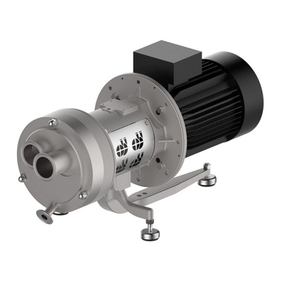
Description Pump overview Description Pump overview Fig.1: SIPLA HT ADAPTA Main components Part no. Designation 0101 Pump housing 0153 Suction nozzle 0156 Pressure nozzle 0180 Dome stand 0330 Bearing support 0680 Casing 0801 Motor Description SIPLA HT is a self-priming, single-stage side-channel pump. All parts in contact with medium are designed according to hygiene criteria. -
Page 15: Pump Name
Number of Pump name Size Design type Nominal width poles [kW] Type plate GEA Hilge Niederlassung der GEA Tuchenhagen GmbH Hilgestrasse - D - 55294 Bodenheim Pump-Type: Ser.-No.: TAG No.: YOM: Made in Germany Fig.2: Type plate GEA Hilge Pump type: Pump name P: Motor rating Serial No.: Serial number... -
Page 16: Transport And Storage
Transport and Storage Special personnel qualification for transport and storage Transport and Storage Special personnel qualification for transport and storage Transports may only be carried out by qualified staff, who must observe the safety instructions. Safety precautions for transport and storage Warning! Falling loads Danger from falling loads. -
Page 17: Attachment Points For Lifting Loads
Transport and Storage Dimensions / weights 4.2.1 Attachment points for lifting loads Fig.3: Attachment points Dimensions / weights Depending on the features of the pump the weights vary a lot. Please contact the manufacturer for concrete information stating the pump number. Unpacking the pump All of our pumps leave our warehouse properly packaged to avoid damage in transit. -
Page 18: Disposal Of Packaging Material
Transport and Storage Disposal of packaging material Disposal of packaging material The generation of waste should be avoided or minimized wherever possible. Surpluses and packaging materials not suitable for recycling should be disposed of through an approved waste disposal company. Packaging materials not suitable for recycling must always be disposed of in accordance with the requirements of environmental protection and waste disposal legislation as well as the requirements of the local authorities. -
Page 19: Technical Data
ISO 9906: 2012, Grade 3B and documented with the acceptance report. Filling capacities Size Filling capacity [l] GEA Hilge SIPLA HT 12.1 GEA Hilge SIPLA HT 18.1 GEA Hilge SIPLA HT 28.1 GEA Hilge SIPLA HT 52.1 Noise emissions Measured values in accordance with DIN EN ISO 3746 for pump units, measuring uncertainty 3 DB(A). -
Page 20: Maximum Operating Pressure
Technical data Maximum operating pressure Operating temperatures Design Temp. [°C] Normal version Sterilisation (SIP) Other temperatures on request. Maximum operating pressure Warning! Pressure overload of the pump! ► Operate the pump according to the ordering data. ► Never exceed the specified maximum operating pressures. The pump’s maximum operating pressure pump depends on various factors: •... - Page 21 Technical data Sealing resistance table Gasket material Medium Temperature (general operating temperature) EPDM -40...+135°C -10...+200 °C (-40...275°F) (+14...+392°F) Caustics up to 3% up to 80 °C (176°F) Caustics up to 5% up to 40 °C (104°F) Caustics up to 5% up to 80 °C (176°F) –...
-
Page 22: Assembly And Installation
Assembly and installation Safety precautions for setup, installation, and connection Assembly and installation Safety precautions for setup, installation, and connection Warning! Tipping (tilting) of the pump! ► The surface for setting up the pump should be clean, level and have sufficient load-bearing capacity. -
Page 23: Special Personnel Qualification
Assembly and installation Special personnel qualification Warning! Overheating! ► Ensure adequate ventilation. ► Avoid sucking in the heated exhaust air also of adjacent units. ► Maintain minimum distances. Caution! Vibration! ► Ensure stable construction for mounting of the pump and piping. Insufficiently stiffened substructures may cause an overall structure capable of oscillating, which is excited to oscillate by hydraulic and/or motor forces during changing operating conditions in the system. -
Page 24: Checking Smooth Running Of The Impeller
Assembly and installation Setup, installation, and connection 6.3.1 Checking smooth running of the impeller Before installation, check that the impeller is running smoothly. Perform the following steps: Remove the motor shroud (only for SUPER version). Remove the motor fan cover. Note the pump’s direction of rotation (arrow). -
Page 25: Installation In The Piping System
Assembly and installation Setup, installation, and connection 6.3.3 Installation in the piping system Fig.5: Installation in the piping system top: Inlet operation | bottom: Suction operation | P - Pump | M - Motor 6.3.3.1 Space requirements Maintain the following minimum distances. Pay attention to motor performance. - Page 26 Assembly and installation Setup, installation, and connection Foundation Vibration damping is best achieved if the pump is set up on a flat, solid concrete foundation. As a guideline, the concrete foundation should be 1.5 times as heavy as the pump. Vibration damper To avoid the transmission of vibrations to the building, it is recommended to disconnect the pump foundation from parts of the building using vibration...
-
Page 27: Using The Mechanical Seal
Assembly and installation Setup, installation, and connection • Damage to shaft/hub connections • Cracks on pump ports • Loosening of screw connections • Cable breaks in the motor connection • Contacting of pump impellers. Acoustic decoupling Fig.7: Example of a foundation of a pump A - expansion joints | B - solid base | C - vibration damper 6.3.4 Using the mechanical seal... -
Page 28: Flushing Connections (Optional)
Assembly and installation Setup, installation, and connection 0433.00 Fig.8: Lubrication film between the sliding surfaces P - Pump side | A - Atmosphere side | L - Lubrication side | 0433.00 - Mechanical seal 6.3.5 Flushing connections (optional) 6.3.5.1 Flush connections for double mechanical seals (optional) 6.3.5.2 Double mechanical seals (optional) Pumps with double-acting mechanical seals are equipped with a seal cartridge. -
Page 29: Double Mechanical Seal - Tandem Arrangement And Quench (Optional)
Assembly and installation Setup, installation, and connection 6.3.5.3 Double mechanical seal - tandem arrangement and quench (optional) Flushing fluid To maintain their function, mechanical seals need a flushing fluid, which has the following tasks, including others: • Dissipation of any leakage •... -
Page 30: Single-Acting Flushed Mechanical Seal
Assembly and installation Setup, installation, and connection • no chemical or mechanical attacking of the pump materials, sealing materials, and elastomers. • No contaminating of the pumped fluid • Viscosity < 5 mPas • Water hardness < 5° dH Demineralised water meets these requirements to a large extent. 6.3.5.5 Single-acting flushed mechanical seal Flushing fluid To maintain their function, mechanical seals need a flushing liquid, which has the... -
Page 31: Electrical Connection
Assembly and installation Setup, installation, and connection 6.3.6 Electrical connection Danger Electric shock by touching live parts! ► Have the electrical connections be made by a licensed electrician. ► Observe local laws, standards and regulations - especially safety precautions. 6.3.6.1 Star connection Star connection for high voltage. -
Page 32: Checking The Direction Of Rotation After Connecting
Assembly and installation Setup, installation, and connection Operation with frequency converter Operating Conditions Measures Install a dU/dt filter between the motor and frequency Noise-sensitive applications converter (reduces voltage spikes and thus noise). Particularly noise-sensitive application Install sinusoidal filter. Use a cable which satisfies the conditions prescribed Cable length by the manufacturer of the frequency converter. - Page 33 Assembly and installation Earthing the motor Equipotential bonding for the motor is performed via the protective conductor connection in the terminal box. Earthing the machine pad support Equipotential bonding of the machine pad support is achieved via the screw connection to the motor. Use a toothed washer at the appropriate position (B). Fig.12: Earthing ADAPTA setups top: Version with stainless steel hood...
-
Page 34: Commissioning
Commissioning Special personnel qualification Commissioning Special personnel qualification The commissioning personnel must be suitably qualified for this work. See also Section 2.6, Page 12. Safety instructions for commissioning Caution! Hazard due to overheating and pressure overload! ► Never pump for longer than 30 seconds against a closed shut-off device. Pumping against a closed shut-off device leads to rapid warming of the pumped fluid and pressure increase. -
Page 35: Functional Testing Of The Mechanical Seal
Commissioning Slowly open the pressure side stop valve. → This completes the commissioning. If there is no increase of delivery head after commissioning: Switch off the pump. Again vent the pump (system). Repeat steps 7 to 10, and follow . 7.3.3 Functional testing of the mechanical seal Perform the following steps:... -
Page 36: Cleaning
Cleaning Special personnel qualification Cleaning To ensure the quality of sensitive fluids, pumps must be cleaned immediately after each use. Only in this way will adhesions and deposits be removed completely and contamination of the products be prevented. To achieve the best possible results, Hilge pumps are optimised with regard to gap and dead spaces, designed according to DIN EN 13951, and resistant to the cleaning agents referred to in the following chapter. -
Page 37: Sip
Cleaning Cleaning and disinfecting agents [°C] (°F) [mg/l] NaOH 2.5% 13-14 85 (185) 60 (140) 0.0075% 90 (194) 0.15% 20 (68) 50 mg/l act. Iodophore 30 (86) >3 Iodine Cleaning agents that contain hydrochloric acid (HCl) or hydrofluoric acid (HF) must not be used. - Page 38 Cleaning – Regular manual external cleaning of the pump unit facilitates proper operation. – Always check the impermeability of the motor (terminal box, condensation water holes) before each cleaning. – Clean the outside of the pump with a soft cloth or brush and use warm water if necessary.
-
Page 39: Maintenance / Servicing
Inspections The pump is maintenance-free for the most part. In order to prevent possible malfunctions, GEA recommends that regular visual inspections be carried out. Special attention should be paid to the leak tightness and the correct functioning of the pump. -
Page 40: Maintenance Intervals
Grease quantities for installation Size 0326.00 0326.00 Part no. open bearing open bearing GEA Hilge SIPLA HT 12.1 17 g GEA Hilge SIPLA HT 18.1 47.4 g GEA Hilge SIPLA HT 28.1.1 47.4 g GEA Hilge SIPLA HT 52.1 47.4 g 430BAL013361GB_1 19.03.2019... -
Page 41: Bearing Replacement
Maintenance / servicing Maintenance of the ADAPTA bearing 9.4.2 Bearing replacement Replace the bearings after approx. 15,000 to 20,000 hours of operation to ensure trouble-free pump operation. 9.4.3 Premature bearing replacement In case of continuous wear-promoting external influences such as •... - Page 42 Maintenance / servicing Maintenance of the ADAPTA bearing Roller bearing greases Storage temperature <70 °C Storage temperature > 70 °C / < 100 °C Delivery fluid -10…95 °C Delivery fluid 96 °C...190 °C N= 140 °C R = 180 °C also permitted: also permitted: Upper usage temperature...
-
Page 43: Maintenance Of The Motor
Maintenance / servicing Maintenance of the motor Maintenance of the motor Motors without grease nipple Motors without grease nipple are equipped with lifetime lubrication. The grease life then depends on the bearing life. Prerequisite is that the motor must be used according to the specifications in the catalogue. -
Page 44: Malfunctions / Repairs
Malfunctions / repairs Special personnel qualification Malfunctions / repairs 10.1 Special personnel qualification The troubleshooting / repair personnel must be suitably qualified for this work. See also Section 2.6, Page 12. 10.2 Safety instructions Warning! Improper execution of work! ► Repair work should be carried out by authorised and qualified personnel. Danger Electric shock by touching live parts! ►... -
Page 45: Malfunctions And Remedies
Malfunctions / repairs Malfunctions and remedies Caution! Unsuitable tools! ► Make sure that all the parts can be mounted without damage. ► Use GEA Hilge assembly tools. 10.3 Malfunctions and remedies Actions for troubleshooting Malfunction Cause Remedy Pump does not Incorrect electrical connection (2 phases). -
Page 46: Repair
Malfunctions / repairs Repair Actions for troubleshooting Malfunction Cause Remedy Leakage at the Pump is strained (causing leaks at the pump body Install pump without strain, support piping by fixed pump body, or at the connections). points. connections, mechanical seal, Housing seals and connection seals defective. -
Page 47: Gea Hilge Assembly Tool Kit
Malfunctions / repairs Repair 10.4.2 GEA Hilge assembly tool kit Tools from the GEA Hilge assembly tool kit prevent damage to the mechanical seal during assembly. Fig.14: GEA Hilge assembly tool kit 10.4.2.1 Contents and use Tools for the GEA Hilge SIPLA HT pumps... -
Page 48: Disassemble The Pump
Malfunctions / repairs Repair Tools for the GEA Hilge SIPLA HT pumps Item Designation Ø 28 Plastic adapter Ø 19 T-handle with 1/2” square ● 10.4.3 Disassemble the pump Disassembly of the pump is carried out in the reverse order of assembly. -
Page 49: Cleaning The Components Before Assembly
0346.00 0360.01 0934.01 0504.18 0920.01 0934.03 0902.05 0902.00 0920.22 0934.02 0180.00 0902.01 0920.02 Fig.15: GEA Hige SIPLA HT ADAPTA Part no. Description Part no. Description 0101.00 Ring housing 0901.04 Hex head screw 0161.00 Back plate 0902.00 Stud screw 0180.00 Dome stand 0902.01... - Page 50 Malfunctions / repairs Repair Part no. Description Part no. Description 0421.01 Radial shaft sealing ring 0920.02 Hexagon nut 0433.00 Axial face seal 0920.09 Hexagon nut 0433.01 Axial face seal 0920.22 Hexagon nut 0491.00 Seal cartridge 0922.00 Impeller nut 0504.18 Spacer ring 0926.00 Locknut 0507.02...
-
Page 51: Installing Adapta Bearing Supports Size 1 And 2
Malfunctions / repairs Repair 10.4.6 Installing ADAPTA bearing supports size 1 and 2 Installing ADAPTA bearing supports size 1 and 2 Push the roller bearings (0326.00) onto the shaft (0211.00). Fix the roller bearings (0236.00) with the locknut (0926.00). torque: 120-140 Nm. Replace the locknut when replacing the bearings. - Page 52 Malfunctions / repairs Repair Installing ADAPTA bearing supports size 1 and 2 Fasten the bearing cover (0360.01), using the spring washers (0934.05) and hex head screws (0901.04). torque: 8 Nm Fig.20: Bearing cover Push the V-ring (0507.05) with greased sealing lip onto the shaft (0211.00) so that the sealing lip contacts the bearing cover (0360.01).
- Page 53 Malfunctions / repairs Repair Installing ADAPTA bearing supports size 1 and 2 Push the coupling half (0840.00) onto the shaft (0211.00). Make sure that the coupling half (0840.00) is flush with the shaft (0211.00). Fig.24: Coupling half, bearing support Fix the coupling half (0840.00) with the set screw (0904.00).
- Page 54 Malfunctions / repairs Repair Installing ADAPTA bearing supports size 1 and 2 Check the coupling pad (0867.02) for wear, and replace if necessary. Fig.28: Coupling pad Push the coupling half (0840.01) onto the motor shaft and secure it with the set screw (0904.01). Make sure that the coupling half (0840.01) is flush with the motor shaft.
- Page 55 Malfunctions / repairs Repair Installing ADAPTA bearing supports size 1 and 2 Align the coupling half (0840.01). Permissible axial offset: 2-4 mm. Fasten the coupling half (0840.01) with the set screw (0904.00). torque: 4 Nm. Fig.32: Feeler gauge Push the splash ring (0507.00) onto the shaft (0211.00).
-
Page 56: Shaft Seals
Fig.36: Double mechanical seal tandem Description in chapter Install double mechanical seal tandem 10.4.8 Installing single mechanical seal Equipment and tools from the GEA Hilge assembly tool kit: • Klüber paste UH1 96-402 • Synthetic material mounting sleeve • Spray bottle See Figure 15, Page 49 Screw the threaded pins (0902.01) into the housing cover (0161.00). -
Page 57: Install Single, Flushed Mechanical Seal (Quench)
(0211.00) as far as it will go. → The single mechanical seal has been installed. 10.4.9 Install single, flushed mechanical seal (Quench) Equipment and tools from the GEA Hilge assembly tool kit: • Klüber paste UH1 96-402 •... -
Page 58: Installing Tandem Double Mechanical Seal
(0211.00) as far as it will go. → The simple, flushed mechanical seal (quench) has been installed. 10.4.10 Installing tandem double mechanical seal Equipment and tools from the GEA Hilge assembly tool kit: • Klüber paste UH1 96-402 •... -
Page 59: Installing Impeller And Pump Housing
Push the rotating unit of the mechanical seal (0433.00) onto the pump shaft (0211.00) as far as it will go. → The double mechanical seal tandem has been installed. 10.4.11 Installing impeller and pump housing Equipment and tools from the GEA Hilge assembly tool kit: • Klüber paste UH1 96-402 •... - Page 60 Malfunctions / repairs Hint! Fig.37: Socket wrench with plastic insert Insert the O-ring (0412.00) into the pump housing (0101.00). Wet the O-ring (0412.00) with water. Mount the pump housing (0101.00) using the threaded pins (0902.02), and cap nuts (0927.00). Torques: M8: 19 Nm | M10: 37 Nm | M12: 65 Nm →...
-
Page 61: Decommissioning
→ The pump has been temporarily decommissioned. 11.4 Disposal Discard the pump or parts thereof in an environment-friendly manner: Use the service of public or private disposal companies. If this is not possible, contact the next GEA Hilge company or service centre. 430BAL013361GB_1 19.03.2019... -
Page 62: Appendix
Appendix Clearance certificate Appendix 12.1 Clearance certificate Von uns, der Unterzeichnerin, wird hiermit, gemeinsam mit dieser Unbedenklichkeitsbescheinigung, folgende Pumpe und deren Zubehör in Inspektions- / Reparaturauftrag gegeben: Angaben zur Pumpe • Typ: • Nr.: • Lieferdatum: Grund des Inspektions- / Reparaturauftrages: Die Pumpe (bitte ankreuzen) ___ wurde nicht in gesundheitsgefährdenden Medien eingesetzt. - Page 63 Appendix 430BAL013361GB_1 19.03.2019...
- Page 64 • GEA is a global technology company with multi-billion euro sales operations in more than 50 countries. Founded in 1881 the company is one of the largest providers of innovative equipment and process technology. GEA is listed in the STOXX ®...
Need help?
Do you have a question about the SIPLA HT ADAPTA 12.1 and is the answer not in the manual?
Questions and answers