
Related Manuals for GEA Hilge HYGIA ADAPTA


Summary of Contents for GEA Hilge HYGIA ADAPTA
- Page 1 Hygienic Pumps GEA Hilge HYGIA ADAPTA (US) - Version C - Version D Operating instruction (Translation from the original language) BA.H2A.ADY.002.GB_1...
- Page 2 (print, photocopy, microfilm or another method) without the prior written permission of GEA Hilge Office of GEA Tuchenhagen GmbH hereinafter referred to as Manufacturer in any form (print, photocopy, microfilm or other process) reproduced or distributed. This restriction also applies to the drawings and diagrams included in the documentation.
- Page 3 – unintended operation and usage conditions, – insufficient maintenance, – improper operation, – incorrect installation, – incorrect or improper connection of electrical components. • resulting or arising from unauthorised modifications or failure to follow the instructions, • caused by use of accessories / spare parts that have not been supplied or recommended by the manufacturer.
- Page 4 LAYOUT INFORMATION Bullet points and numbered list characters Bullet points are used to separate logical contents within a section: • Bullet point 1 Types of bullet point 1. • Bullet point 2 Types of bullet point 2. Numbered list characters are used to separate enumerations within a descriptive text: Descriptive text with consecutive numbering: –...
-
Page 5: Table Of Contents
TABLE OF CONTENTS General Information about this document Manufacturer address Customer Service Safety Intended use 2.1.1 Pumped fluids 2.1.2 Minimum flow rate Minimum flow rates in explosive atmospheres 2.1.3 Connections and piping 2.1.4 Switching frequency 2.1.5 Types 2.1.6 Hygiene classification Safety precautions in these operating instructions Explanation of the safety symbols used Safety instructions for the company/operator... - Page 6 10.3 Malfunctions and remedies 10.4 Repair 10.4.1 Repair order 10.4.2 GEA Hilge assembly tool kit Contents and use 10.4.3 Parts overview 10.4.4 Parts overview of ADAPTA bearing support sizes 1 and 2 10.4.5 Parts overview ADAPTA bearing support size 3 10.4.6...
- Page 7 11.3 Temporary decommissioning 11.4 Disposal Appendix 12.1 Certificate of non-objection BA.H2A.ADY.002.GB_1 18.12.2017...
- Page 8 BA.H2A.ADY.002.GB_1 18.12.2017...
-
Page 9: General
Versions, technical data and spare part numbers are subject to technical change. We reserve the right to implement changes due to technical progress. Manufacturer address GEA Hilge Niederlassung der GEA Tuchenhagen GmbH Hilgestraße 37-47 55294 Bodenheim Germany Phone +49 6135 7016-0 Fax +49 6135 1737 hilge@gea.com... -
Page 10: Safety
Safety Intended use Safety Intended use Warning! Non-intended use! ► Pump only media that are specified in the order. The pump has been specially designed for them. ► Operate the pump only on the electrical grid that was specified in the purchase order. -
Page 11: Safety Precautions In These Operating Instructions
Safety Safety precautions in these operating instructions Safety precautions in these operating instructions Read the safety precautions! These operating instructions contain basic precautions that must be observed during installation, operation and maintenance. They must therefore be read by the installer and relevant personnel or operator prior to installation and commissioning. -
Page 12: Explanation Of The Safety Symbols Used
Safety Explanation of the safety symbols used Explanation of the safety symbols used Danger Stands for an immediate danger which leads to heavy physical injuries or to the death. ► Description to avert the danger Warning! Stands for a possibly dangerous situation which leads to heavy physical injuries or to the death. -
Page 13: Dangers Of Non-Compliance With Safety Information
Safety Unauthorised modification and ordering of spare parts Warning! Hazardous materials Contact with dangerous substances, e.g. by inhalation. ► Discharge the leakage of dangerous goods such that no danger to persons and the environment arises! ► Comply with legal provisions! ►... -
Page 14: Staff Qualifications And Training
Safety Staff qualifications and training Staff qualifications and training The staff for working on and with the pump must have the appropriate qualifications. Responsibilities, competencies and supervision of staff must be clearly defined by the operating company. If personnel do not have the necessary knowledge, they are to be trained and instructed. -
Page 15: Description
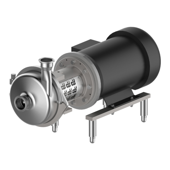
Description Pump overview Description Pump overview 0156.00 0330.00 0680.00 0801.00 0103.00 0153.00 0180.00 Fig.1: GEA Hilge HYGIA ADAPA 0103 Annular casing 0153 Suction port 0156 Discharge port 0180 Combi foot 0330 Bearing housing 0801 Stainless steel shroud 0801 Motor Description The pump is a normal-priming, single-stage centrifugal pump in system block design. -
Page 16: Hygienic Design Applications
Type plate GEA Hilge Niederlassung der Tuchenhagen GmbH Hilgestrasse - D - 55294 Bodenheim Pump-Type: GEA Hilge HYGIA I-1/D-AHUO0-IA0160 OFAF22-211-EEMSE-D Ser.-No.: 990012340001 P/N: 99001234 Q: 50 USgpm P: 5 hp n: 3450 rpm H: 60 ft TAG No.:... - Page 17 Description – General purpose motors These motor variants are used in all applications that are not subject to strict hygiene regulations. BA.H2A.ADY.002.GB_1 18.12.2017...
-
Page 18: Transport And Storage
Transport and Storage Special personnel qualification for transport and storage Transport and Storage Special personnel qualification for transport and storage Transports may only be carried out by qualified staff, who must observe the safety instructions. Safety precautions for transport and storage Warning! Falling loads Danger from falling loads. -
Page 19: Dimensions / Weights
Transport and Storage Dimensions / weights Dimensions / weights Weights HYGIA ADAPTA on motor base | 2 pole NEMA- Total Weight Total Weight BG1/2 [HP] frame size [kg] [lb] 143T 39.5 87.1 145T 43.2 95.2 182T 55.8 123.0 184T 62.6 138.0 184T 77.0... -
Page 20: Unpacking The Pump
Transport and Storage Unpacking the pump Weights HYGIA ADAPTA on spherical stand | 4 pole NEMA- Total Weight Total Weight BG1/2 [HP] frame size [kg] [lb] 143T 45.1 99.4 145T 46.1 101.6 145T 48.1 106.0 182T 83.5 184.1 184T 79.5 175.2 213T 101.5... -
Page 21: Disposal Of Packaging Material
Transport and Storage Disposal of packaging material Disposal of packaging material The generation of waste should be avoided or minimized wherever possible. Surpluses and packaging materials not suitable for recycling should be disposed of through an approved waste disposal company. Packaging materials not suitable for recycling must always be disposed of in accordance with the requirements of environmental protection and waste disposal legislation as well as the requirements of the local authorities. -
Page 22: Technical Data
ISO 9906: 2012, Grade 3B and documented with the acceptance report. Noise emissions Measured values in accordance with DIN EN ISO 3746 for pump units, measuring uncertainty 3 DB(A). Noise emissions GEA Hilge HYGA I / II - 60 Hz [dB (A)] Output [kW] [HP] Number of poles 0.75 (1) -
Page 23: Maximum Operating Temperatures
Technical data Maximum operating temperatures The noise emissions caused by a pump are influenced mainly by its application. The values shown here should therefore be considered merely as a guide. Maximum operating temperatures Warning! Exceeding the maximum temperatures! ► Never exceed the specified operating temperatures. Operating temperatures Design Temp. - Page 24 Technical data Sealing resistance table Gasket material Medium Temperature (general operating temperature) EPDM -40...+135°C -10...+200 °C (-40...275°F) (+14...+392°F) Caustics up to 5% up to 80 °C (176°F) – Caustics at more than 5% – Inorganic acids up to 3% up to 80 °C (176°F) Inorganic acids up to 5% up to 80 °C (176°F) Inorganic acids up to 5%...
-
Page 25: Assembly And Installation
Assembly and installation Safety precautions for setup, installation, and connection Assembly and installation Safety precautions for setup, installation, and connection Warning! Tipping (tilting) of the pump! ► The surface for setting up the pump should be clean, level and have sufficient load-bearing capacity. - Page 26 Assembly and installation Safety precautions for setup, installation, and connection Warning! Overheating! ► Ensure adequate ventilation. ► Avoid sucking in the heated exhaust air also of adjacent units. ► Maintain minimum distances. Caution! Vibration! ► Ensure stable construction for mounting of the pump and piping. Insufficiently stiffened substructures may cause an overall structure capable of oscillating, which is excited to oscillate by hydraulic and/or motor forces during changing operating conditions in the system.
-
Page 27: Mechanical Seals In Tandem Arrangement
Assembly and installation Special personnel qualification 6.1.1 Mechanical seals in tandem arrangement Caution! Missing supply of flushing fluid! Dry running of the mechanical seal. ► Always connect the flushing lines such that supply for flushing is always ensured. ► Ensure that flushing fluid is supplied even when checking the motor’s direction of rotation. -
Page 28: Checking Smooth Running Of The Impeller
Assembly and installation Setup, installation, and connection 6.3.1 Checking smooth running of the impeller Before installation, check that the impeller is running smoothly. Perform the following steps: Remove the motor shroud (only for SUPER version). Remove the motor fan cover. Note the pump’s direction of rotation (arrow). -
Page 29: Installation In The Piping System
Assembly and installation Setup, installation, and connection 6.3.3 Installation in the piping system Fig.5: Installation in the piping system top: Inlet operation | bottom: Suction operation | P - Pump | M - Motor 6.3.3.1 Space requirements Maintain the following minimum distances. Pay attention to motor performance. -
Page 30: Noise And Vibration Damping
Assembly and installation Setup, installation, and connection Vertical assembly 0.75 - 5 hp > 7.5 hp Fig.7: Minimum distances in vertical assembly Settings for the 3-A assembly Installation height of the pump To ensure proper cleaning of the pump environment, the 3-A stand must have a minimum height. - Page 31 Assembly and installation Setup, installation, and connection In general, this should always be considered for pumps with motor sizes starting from 11 kW. But unwanted vibrations and noises occur also with smaller motor sizes. Noise and vibration are caused by the rotating parts in the motor and the pump and by the flow in the pipes and fittings.
-
Page 32: Using The Mechanical Seal
Assembly and installation Setup, installation, and connection The pipes must be started so that they can cause no strain in the compensators and in the pump. Follow the manufacturer's instructions and hand them over to the person responsible or to the plant manufacturer. Vibration may cause the following damage: •... -
Page 33: Flush Connections For Double Mechanical Seals (Optional)
Assembly and installation Setup, installation, and connection If the lubrication film is missing or interrupted between the sliding surfaces, dry running occurs. The friction heat generated by the direct contact of the sliding surfaces leads to the destruction of the mechanical seal. Depending on the material pairing, this can take place within a few seconds. - Page 34 Assembly and installation Setup, installation, and connection 0491.00 Fig.11: Flush ports Inlet line Outlet line Direction of rotation of the pump 0491.00 Seal housing Connecting the flushing Connect the inlet line (A). Note position of the lines depending on the direction of rotation. Connect the outlet line (B).
- Page 35 Assembly and installation Setup, installation, and connection The supply of the mechanical seal with sealing fluid must be pressurised. The sealing pressure should be at least 1.5-2.0 bar (22-29 psi) above the maximum internal pressure of the pump. Max. internal pressure = system pressure + pumping pressure at Q = zero.
-
Page 36: Defective Shaft Seal
Assembly and installation Electrical connection 6.3.5.3 Defective shaft seal Notice! Leakage of liquids. ► If a leak is detected, switch off the pump and replace the shaft seal immediately. Electrical connection 6.4.1 Connect NEMA motors Follow the instructions of the motor manufacturer to connect the power supply. 6.4.2 Frequency converter operation All three-phase motors can be connected to a frequency converter. -
Page 37: Earthing
Assembly and installation Re-install all safety devices. With double mechanical seal in back-to-back arrangement, connect the sealing fluid (see Section 6.3.5, Page 33). Check that hydraulic connections are firmly secured. Open stop valves. With double mechanical seal in tandem arrangement, connect the flushing fluid (see Section 6.3.5, Page 33) Fill the pump (system). -
Page 38: Commissioning
Commissioning Special personnel qualification Commissioning Special personnel qualification The commissioning personnel must be suitably qualified for this work. See also Section 2.6, Page 14. Safety instructions for commissioning Caution! Hazard due to overheating and pressure overload! ► Never pump for longer than 30 seconds against a closed shut-off device. Pumping against a closed shut-off device leads to rapid warming of the pumped fluid and pressure increase. -
Page 39: Functional Testing Of The Mechanical Seal
Commissioning Fully open the suction-side stop valve. Close the pressure side stop valve. Switch on the pump. Slowly open the pressure side stop valve. → This completes the commissioning. If there is no increase of delivery head after commissioning: Switch off the pump. Again vent the pump (system). -
Page 40: Cleaning
Cleaning Special personnel qualification Cleaning To ensure the quality of sensitive fluids, pumps must be cleaned immediately after each use. Only in this way will adhesions and deposits be removed completely and contamination of the products be prevented. To achieve the best possible results, Hilge pumps are optimised with regard to gap and dead spaces, designed according to DIN EN 13951, and resistant to the cleaning agents referred to in the following chapter. -
Page 41: Cip
Cleaning Warning! Pressure shock by evaporating liquid! ► Completely empty the system before steam sterilisation. Notice! Disposal of cleaning agents ► Dispose of cleaning agents properly and in an environmentally friendly way. CIP stands for Cleaning in Place, the pump is completely rinsed with cleaning agents. -
Page 42: Sip
Cleaning SIP stands for sterilisation in place, in which the pump is sterilised with superheated steam. For steam sterilization or sanitization, minimum temperatures of 121 ° C (250 ° F) must be applied to all wetted surfaces. For the maximum allowable temperatures, refer to Section 5.4, Page 23. The pump must not be in operation during steam sterilisation. -
Page 43: Maintenance / Servicing
Inspections The pump is maintenance-free for the most part. In order to prevent possible malfunctions, GEA recommends that regular visual inspections be carried out. Special attention should be paid to the leak tightness and the correct functioning of the pump. -
Page 44: Maintenance Intervals
Maintenance / servicing Maintenance of the ADAPTA bearing – The O-ring has cracks. – The surface of the O-ring is porous and brittle. – The O-ring has lost its elasticity. 9.3.2 Maintenance intervals To ensure the highest operational reliability of the magnetic separator, all wearing parts should be replaced at longer intervals. -
Page 45: Bearing Structure Carrier Size 3
Maintenance / servicing Maintenance of the ADAPTA bearing 9.4.2 Bearing structure carrier size 3 The bearing structure consists of two angular contact ball bearings 0326.00 and one cylindrical roller bearing 0327.00. The two single row angular contact ball bearings make up the bearing structure on the motor-side. They are paired and are installed as fixed bearings in an X-arrangement to accommodate axial and radial forces from all directions. -
Page 46: Grease Filling
Maintenance / servicing Maintenance of the ADAPTA bearing 9.4.5 Grease filling In the factory, the cavities between the rolling elements are completely filled with grease. The grease is encapsulated by the V rings (0507.02) and (0507.05) and is designed as grease filling for normal environmental conditions. Refer to the following chapters for the grease quantities during installation. -
Page 47: Maintenance Of The Motor
Maintenance / servicing Maintenance of the motor Maintenance of the motor Motors without grease nipple Motors without grease nipple are equipped with lifetime lubrication. The grease life then depends on the bearing life. Prerequisite is that the motor must be used according to the specifications in the catalogue. -
Page 48: Malfunctions / Repairs
Malfunctions / repairs Special personnel qualification Malfunctions / repairs 10.1 Special personnel qualification The troubleshooting / repair personnel must be suitably qualified for this work. See also Section 2.6, Page 14. 10.2 Safety instructions Warning! Improper execution of work! ► Repair work should be carried out by authorised and qualified personnel. Danger Electric shock by touching live parts! ►... -
Page 49: Malfunctions And Remedies
Malfunctions / repairs Malfunctions and remedies Caution! Unsuitable tools! ► Make sure that all the parts can be mounted without damage. ► Use GEA Hilge assembly tools. 10.3 Malfunctions and remedies Actions for troubleshooting Malfunction Cause Remedy Pump does not Incorrect electrical connection (2 phases). -
Page 50: Repair
Malfunctions / repairs Repair Actions for troubleshooting Malfunction Cause Remedy Leakage at the Pump is strained (causing leaks at the pump body Install pump without strain, support piping by fixed pump body, or at the connections). points. connections, mechanical seal, Housing seals and connection seals defective. - Page 51 Malfunctions / repairs Repair If, despite careful emptying and cleaning of the pump, safety precautions are required, the necessary information must be given. BA.H2A.ADY.002.GB_1 18.12.2017...
-
Page 52: Gea Hilge Assembly Tool Kit
Malfunctions / repairs Repair 10.4.2 GEA Hilge assembly tool kit Tools from the GEA Hilge assembly tool kit prevent damage to the mechanical seal during assembly. Fig.14: GEA Hilge assembly tool kit 10.4.2.1 Contents and use Tools in the GEA Hilge assembly tool kit... -
Page 53: Parts Overview
Malfunctions / repairs Repair 10.4.3 Parts overview 0161.00 0901.07 0412.00 0412.04 0927.00 0230.00 0934.03 0930.00 0902.02 0433.00 0922.00 0557.00 0934.00 0920.00 0412.05 0920.04 0554.00 0940.00 0501.00 0211.00 0103.00 0412.04 0230.00 0930.00 0922.00 0433.00 0557.00 0412.05 0103.00 0161.00 0412.00 0501.01 0905.00 Fig.15: Parts overview –... -
Page 54: Parts Overview Of Adapta Bearing Support Sizes 1 And 2
Malfunctions / repairs Repair 10.4.4 Parts overview of ADAPTA bearing support sizes 1 and 2 Fig.16: Bearing supports up to motor frame size 160 Parts list of ADAPTA bearing support sizes 1 and 2 Pcs. Part no. Designation Pcs. Part no. Designation 0211.00 Pump shaft... -
Page 55: Parts Overview Adapta Bearing Support Size 3
Malfunctions / repairs Repair 10.4.5 Parts overview ADAPTA bearing support size 3 Fig.17: Parts overview bearing support of motor frame size180 and larger Parts list ADAPTA bearing support size 3 Pcs. Part no. Designation Pcs. Part no. Designation 0211.00 Pump shaft 0686.00 Safety guard 0326.00... -
Page 56: Parts Overview Of Coupling And Motor
Malfunctions / repairs Repair 10.4.6 Parts overview of coupling and motor Fig.18: Parts overview of coupling and motor Parts list of coupling, motor, casing Pcs. Part no. Designation Pcs. Part no. Designation 0211.00 Shaft 0867.02 Coupling insert 0346.00 Intermediate lantern 0901.02 Hex screw 0554.02... -
Page 57: Installation Instructions
Malfunctions / repairs Repair 10.4.7 Installation instructions Notice! Hygiene risk, food safety Incorrect installation of the pump can cause subsequent contamination and thus impair food safety. ► Always observe the following instructions: – Use tools from the HILGE assembly tool kit for installation. –... -
Page 58: Installing Adapta Bearing Supports Size 1 And 2
Malfunctions / repairs Repair 10.4.8 Installing ADAPTA bearing supports size 1 and 2 Installing ADAPTA bearing supports size 1 and 2 Push the roller bearings (0326.00) onto the shaft (0211.00). Fix the roller bearings (0236.00) with the locknut (0926.00). torque: 89 - 103 ft lb (120-140 Nm). Replace the locknut when replacing the bearings. - Page 59 Malfunctions / repairs Repair Installing ADAPTA bearing supports size 1 and 2 Fasten the bearing cover (0360.01), using the spring washers (0934.05) and hex head screws (0901.04). torque: 6 ft lb (8 Nm) Fig.23: Bearing cover Push the V-ring (0507.05) with greased sealing lip onto the shaft (0211.00) so that the sealing lip contacts the bearing cover (0360.01).
- Page 60 Malfunctions / repairs Repair Installing ADAPTA bearing supports size 1 and 2 Push the coupling half (0840.00) onto the shaft (0211.00). Make sure that the coupling half (0840.00) is flush with the shaft (0211.00). Fig.27: Coupling half, bearing support Fix the coupling half (0840.00) with the set screw (0904.00).
- Page 61 Malfunctions / repairs Repair Installing ADAPTA bearing supports size 1 and 2 Check the coupling pad (0867.02) for wear, and replace if necessary. Fig.31: Coupling pad Push the coupling half (0840.01) onto the motor shaft and secure it with the set screw (0904.01). Make sure that the coupling half (0840.01) is flush with the motor shaft.
- Page 62 Malfunctions / repairs Repair Installing ADAPTA bearing supports size 1 and 2 Align the coupling half (0840.01). Permissible axial offset: 2-4 mm (0.08"-0.16"). Fasten the coupling half (0840.01) with the set screw (0904.00). torque: 3 ft lb (4 Nm). Fig.35: Feeler gauge Push the splash ring (0507.00) onto the shaft (0211.00).
-
Page 63: Installing Adapta Bearing Support Bg 3
Malfunctions / repairs Repair 10.4.9 Installing ADAPTA bearing support BG 3 Equipment and tools from the GEA Hilge assembly tool kit • Klüber paste UH1 96-402 Installing ADAPTA bearing support size 3 Slide the outer race of the cylindrical roller bearing (0327.00) from the pump side into the bearing... - Page 64 Malfunctions / repairs Repair Installing ADAPTA bearing support size 3 Push the shaft (0211.00) along with the angular contact ball bearings (0326.00) into the bearing support (0330.00). Fig.41: Shaft Install the pump side spacer (0504.01) and retaining ring (0932.00). Fig.42: Bearing cover Clean the bearing cover (0360.01) on the motor side.
- Page 65 Malfunctions / repairs Repair Installing ADAPTA bearing support size 3 Push the V-rings (0507.02) and (0507.05) with greased sealing lips from both sides onto the shaft (0211.00) so that the sealing lips contact the bearing caps (0360.00/01). Fig.45: V-rings Insert the feather key (0940.01) into the shaft (0211.00).
- Page 66 Malfunctions / repairs Repair Installing ADAPTA bearing support size 3 Screw in the set screw (0904.01). torque: M8 - 6 ft lb (8 Nm). Fig.49: Set screw Grease the stud bolts (0902.06) with Klüber paste UH1 96-402. Fig.50: Stud bolts Screw the stud bolts (0902.06) into the bearing support (0330.00).
- Page 67 Malfunctions / repairs Repair Installing ADAPTA bearing support size 3 Insert the feather key (0940.02) into the motor shaft. Fig.53: Feather key Check the coupling pad (0867.02) for wear and replace if necessary. Fig.54: Coupling pad Push the coupling half (0840.01) onto the motor shaft and secure it with the set screw (0904.01).
- Page 68 Malfunctions / repairs Repair Installing ADAPTA bearing support size 3 Connect the bearing carrier (0330.00) and motor (0801.00) with the spring washers (0934.06) and hex nuts (0920.09). Fig.57: Bearing support Align the coupling half (0840.01). Permissible axial offset of the coupling halves: 4 mm (0.16") Fig.58: Axial offset Fasten the coupling half (0840.01) with the set...
-
Page 69: Installing Single Mechanical Seal
Malfunctions / repairs Repair 10.4.10 Installing single mechanical seal Equipment and tools from the GEA Hilge assembly tool kit • Loctite Type 243 • Klüber paste UH1 96-402 Connecting the back plate with the bearing support Wet the threads of the stud bolts (0902.00) with Loctite Type 243 and screw them by hand (!) into the back plate (0161.00). -
Page 70: Determining Gap Size On Hygia
Malfunctions / repairs Repair 10.4.11 Determining gap size on HYGIA Fig.63: Gap size on HYGIA General The gap size needs to be determined only if modifying/replacing the impeller or the ring housing. The gap between the impeller and the annular casing contributes crucially to complying with the intended use. - Page 71 Malfunctions / repairs Repair Carefully place the annular casing (0103.00) against the back plate (0161.00). Thus, the impeller (0230.00) is pushed by the annular casing (0103.00) into the zero gap position. The air gap then forms behind the impeller. Remove annular casing (0103.00) so that the impeller (0230.00) does not move, retaining its position.
-
Page 72: Installing Single Conical Spring Mechanical Seal
Malfunctions / repairs Repair 10.4.12 Installing single conical spring mechanical seal Equipment and tools from the GEA Hilge assembly tool kit • Spray bottle • Plastic mounting sleeve • Mounting sleeve Installing single conical spring mechanical seal Wet the fixed ring (counter ring) of the mechanical seal (0433.00) and the shaft (0211.00) with clean... - Page 73 Malfunctions / repairs Repair Installing single conical spring mechanical seal Push the rotating unit of the mechanical seal (0433.00) in the assembled state onto the shaft (0211.00) as far as it will go. Fig.67: Mechanical seal Push the seal spacer (0557.00) onto the shaft. Fig.68: Seal spacer →...
-
Page 74: Installing The Single Mechanical Seal - Spring Encapsulated (Hygiene)
– Easy to clean – For adhesive media – Optimal arrangement in the pump chamber Equipment and tools from the GEA Hilge assembly tool kit: • Spray bottle • Plastic mounting sleeve Prior to installation Check the shaft and counter ring holder for impurities and damage (sharp edges). - Page 75 Malfunctions / repairs Repair Check all O-rings of the mechanical seal for correct seating, and adjust if necessary. Moisten all sliding O-rings with water. → Done. Assembly Slide the fixed ring (counter ring) of the mechanical seal (0433.00) along with the O-ring over the shaft into the seat.
-
Page 76: Installing Double Mechanical Seal
Repair 10.4.14 Installing double mechanical seal Hint! This section applies to the installation of the double mechanical seal in back-to-back and tandem arrangements Equipment and tools from the GEA Hilge assembly tool kit • Spray bottle • Plastic mounting sleeve •... - Page 77 Connect the seal cartridge (0491.00) with the back plate (0161.00) GEA Hilge HYGIA I: Fastening from the front with Phillips screws (1000.03) Torque: M4: 1.1 - 1.5 ft lb (1.5 - 2 Nm) GEA Hilge HYGIA II: Fastening from the rear with hex socket screws (0914.02), washer (0554.03).
- Page 78 Connecting the seal cartridge GEA Hilge HYGIA I / II The seal cartridge is required for the double mechanical seal. Its mounting is very similar for the GEA Hilge HYGIA I and GEA Hilge HYGIA II. Fig.77: Connection of seal cartridge...
- Page 79 Malfunctions / repairs Repair Installing double mechanical seal Wet the fixed ring (counter ring) of the mechanical seal (0433.01) and the shaft (0211.00) with clean water. Fig.80: Fixed ring of the mechanical seal Push the fixed ring (counter ring) of the mechanical seal (0433.01) with the mounting sleeve into the seat of the seal cartridge (0491.00).
- Page 80 Malfunctions / repairs Repair Installing double mechanical seal Push the rotating unit (slide ring) of the mechanical seal (0433.01) into the shaft (0211.00) as far as it will go in the assembled state with the mounting sleeve. Fig.83: Slide ring of the mechanical seal Remove the mounting sleeve.
-
Page 81: Installing Tandem Double Mechanical Seal
Malfunctions / repairs Repair 10.4.15 Installing tandem double mechanical seal Equipment and tools from the GEA Hilge assembly tool kit • Spray bottle • Plastic mounting sleeve • Mounting sleeve • Loctite Type 243 • Klüber paste UH1 96-402 •... - Page 82 Malfunctions / repairs Repair Installing tandem double mechanical seal Wet the O-ring (0412.03) with water and insert it into the sterile screws (0918.00). Fig.88: Sterile screw Insert the O-ring (0412.01) into the seal cover (0471.00). Fig.89: Seal cover Use the sterile screws (0918.00) to fasten the seal cover (0471.00) to the back plate (0161.00).
-
Page 83: Installing Double Mechanical Seal In Back-To-Back Position
Malfunctions / repairs Repair 10.4.16 Installing double mechanical seal in back-to-back position Installing double mechanical seal in back-to-back position Hint! Start by following the steps in Section 10.4.15, Page 81. Push the adjusting ring (0516.00) onto the shaft (0211.00). Wet the mounting sleeve with clean water and push it onto the shaft shoulder. - Page 84 Malfunctions / repairs Repair Installing double mechanical seal in back-to-back position Wet the O-ring (0412.03) with water and insert it into the sterile screws (0918.00). Fig.94: Sterile screw Use the sterile screws (0918.00) to fasten the seal cover (0471.00) to the back plate (0161.00). torque: M6: 6 lbf ft (8 Nm).
-
Page 85: Installing Impeller And Housing
Malfunctions / repairs Repair 10.4.17 Installing impeller and housing Equipment and tools from the GEA Hilge assembly tool kit: • Klüber paste UH1 96-402 • Extractor • Spray bottle • Socket wrench • Socket wrench bit Install impeller Insert the feather key (0940.00). - Page 86 Malfunctions / repairs Repair Install impeller Install impeller (0230.00). Fig.99: Impeller Grease the thread of the impeller nut (0922.00) with Klüber paste. Fig.100: Impeller nut Grease lock washer (0930.00) with Klüber paste. Hint! Only use original spare part lock washers from Hilge for securing the impeller mounting.
- Page 87 Malfunctions / repairs Repair Install impeller Replace lock washers (0930.00) after 5-time use. Fig.103: Lock washer Insert the lock washers (0930.00) into the impeller nut (0922.00). Fig.104: Lock washers in impeller Unscrew impeller nut (0922.00) by hand. Leave a gap of approximately 0.12 "(3 mm) for the O-ring (0412.04).
- Page 88 Malfunctions / repairs Repair Install impeller To prevent damage, use socket wrench with bit to tighten the impeller nut (0922.00). Notice! Hygiene risk, food safety Damaged and scratched surfaces can cause contamination. ► Always tighten impeller nut with socket Fig.107 wrench and insert.
- Page 89 Malfunctions / repairs Repair Installing the KLM housing Wet the O-ring (0412.00) with water and insert it into the back plate (0161.00). Fig.110: Back plate, O-ring Install the annular casing (0103.00). Fig.111: Annular casing Grease the thread of the connecting screw (0905.00) with Klüber paste.
- Page 90 Malfunctions / repairs Repair Installing the KLM housing Align the annular casing (0103.00) via the pressure piece using a mechanic’s spirit level. Fig.113: Annular casing Tighten the hex nut (0920.00). Torque M10: 26 lbf ft (35 Nm). Use a plastic mallet to bring the clamp ring into the correct position.
-
Page 91: Installing The Wear Inserts
Malfunctions / repairs 10.4.18 Installing the wear inserts Attaching the wear inserts Install the wear inserts (0686.01) and (0686.02) with the screws (1000.11). Fig.116: Wear inserts on the lantern → The wear inserts are installed. BA.H2A.ADY.002.GB_1 18.12.2017... -
Page 92: Decommissioning
→ The pump has been temporarily decommissioned. 11.4 Disposal Discard the pump or parts thereof in an environment-friendly manner: Use the service of public or private disposal companies. If this is not possible, contact the next GEA Hilge company or service centre. BA.H2A.ADY.002.GB_1 18.12.2017... - Page 93 Appendix Appendix BA.H2A.ADY.002.GB_1 18.12.2017...
- Page 94 Appendix Certificate of non-objection 12.1 Certificate of non-objection BA.H2A.ADY.002.GB_1 18.12.2017...
- Page 95 Appendix Certificate of non-objection This section contains a certificate of non-objection. In the event of inspection or repair send the pump including this certificate to HILGE. Certificate of non-objection The following pump and its accessories, together with this certificate of non-objection, are herewith contracted out by the undersigned for inspection/repair: Pump data •...
- Page 96 • GEA is a global technology company with multi-billion euro sales operations in more than 50 countries. Founded in 1881 the company is one of the largest providers of innovative equipment and process technology. GEA is listed in the STOXX ®...
Need help?
Do you have a question about the Hilge HYGIA ADAPTA and is the answer not in the manual?
Questions and answers