GEA Hilge HYGIA K Operating Instruction
Hide thumbs
Also See for Hilge HYGIA K:
- Operating manual (36 pages) ,
- Operating instructions manual (94 pages)

Subscribe to Our Youtube Channel
Related Manuals for GEA Hilge HYGIA K


Summary of Contents for GEA Hilge HYGIA K
- Page 1 Hygienic Pumps GEA Hilge HYGIA K Operating instruction (Translation from the original language) BA.H2A.KYY.001.GB_2...
- Page 2 (print, photocopy, microfilm or another method) without the prior written permission of GEA Hilge Niederlassung der GEA Tuchenhagen GmbH hereinafter referred to as Manufacturer This restriction also applies to the drawings and diagrams included in the documentation. LEGAL NOTICE These instructions are part of the technical documentation for the scope of delivery.
- Page 3 – unintended operation and usage conditions, – insufficient maintenance, – improper operation, – incorrect installation, – incorrect or improper connection of electrical components. • resulting or arising from unauthorised modifications or failure to follow the instructions, • caused by use of accessories / spare parts that have not been supplied or recommended by the manufacturer.
- Page 4 LAYOUT INFORMATION Bullet points and numbered list characters Bullet points are used to separate logical contents within a section: • Bullet point 1 Types of bullet point 1. • Bullet point 2 Types of bullet point 2. Numbered list characters are used to separate enumerations within a descriptive text: Descriptive text with consecutive numbering: –...
-
Page 5: Table Of Contents
TABLE OF CONTENTS General Information about this document Manufacturer address Customer Service EU Declaration of Conformity for Machines Safety Intended use 2.1.1 Pumped fluids 2.1.2 Minimum flow rate Minimum flow rates in explosive atmospheres 2.1.3 Connections and piping 2.1.4 Switching frequency 2.1.5 Types Safety precautions in these operating instructions... - Page 6 10.2 Safety instructions 10.3 Malfunctions and remedies 10.4 Repair 10.4.1 Repair order 10.4.2 GEA Hilge assembly tool kit Contents and use 10.4.3 Parts overview 10.4.4 Parts overview for K motor stool 10.4.5 Parts overview of drive 10.4.6 Disassemble the pump 10.4.7...
-
Page 7: General
Versions, technical data and spare part numbers are subject to technical change. We reserve the right to implement changes due to technical progress. Manufacturer address GEA Hilge Niederlassung der GEA Tuchenhagen GmbH Hilgestraße 37-47 55294 Bodenheim Germany Phone +49 6135 7016-0 Fax +49 6135 1737 hilge@gea.com... -
Page 8: Eu Declaration Of Conformity For Machines
EU Declaration of Conformity for Machines in accordance with the EC Machinery Directive 2006/42/EC, Annex II 1. A Manufacturer: GEA HILGE Office of GEA Tuchenhagen GmbH Hilgestrasse 37-47 D 55294 Bodenheim Germany We declare under our sole responsibility that the machine... -
Page 9: Safety
Safety Intended use Safety Intended use Warning! Non-intended use! ► Pump only media that are specified in the order. The pump has been specially designed for them. ► Operate the pump only on the electrical grid that was specified in the purchase order. - Page 10 Safety Safety precautions in these operating instructions These operating instructions contain basic precautions that must be observed during installation, operation and maintenance. They must therefore be read by the installer and relevant personnel or operator prior to installation and commissioning. The operating instructions must always be available at machine/ system site.
-
Page 11: Explanation Of The Safety Symbols Used
Safety Explanation of the safety symbols used Explanation of the safety symbols used Danger Stands for an immediate danger which leads to heavy physical injuries or to the death. ► Description to avert the danger Warning! Stands for a possibly dangerous situation which leads to heavy physical injuries or to the death. -
Page 12: Dangers Of Non-Compliance With Safety Information
Safety Unauthorised modification and ordering of spare parts Warning! Hazardous materials Contact with dangerous substances, e.g. by inhalation. ► Discharge the leakage of dangerous goods such that no danger to persons and the environment arises! ► Comply with legal provisions! ►... -
Page 13: Staff Qualifications And Training
Safety Staff qualifications and training Staff qualifications and training The staff for working on and with the pump must have the appropriate qualifications. Responsibilities, competencies and supervision of staff must be clearly defined by the operating company. If personnel do not have the necessary knowledge, they are to be trained and instructed. - Page 14 Safety – failure of the control circuit or control loop – incorrect assembly – fracture during operation – operating media or objects getting thrown out – loss of stability – personnel slipping, tripping or falling BA.H2A.KYY.001.GB_2 27.02.2018...
-
Page 15: Description
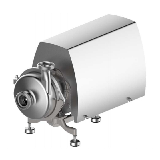
Description Pump overview Description Pump overview 0340 0801 0156 0103 0153 0180 Fig.1: GEA Hilge HYGIA K 0103 Ring housing 0153 Suction nozzle 0156 Pressure nozzle 0180 Stainless steel foot 0340 Motor stool 0801 Motor Description The pump is a normal-priming, single-stage centrifugal pump in system block design. -
Page 16: Pump Name
Output Pump name Size Design type Nominal width Number of poles [kW] Type plate GEA Hilge Niederlassung der GEA Tuchenhagen GmbH Hilgestrasse - D - 55294 Bodenheim Pump-Type: Ser.-No.: TAG No.: YOM: Made in Germany Fig.2: Type plate GEA Hilge... -
Page 17: Transport And Storage
Transport and Storage Special personnel qualification for transport and storage Transport and Storage Special personnel qualification for transport and storage Transports may only be carried out by qualified staff, who must observe the safety instructions. Safety precautions for transport and storage Warning! Falling loads Danger from falling loads. -
Page 18: Dimensions / Weights
Transport and Storage Dimensions / weights Dimensions / weights The weights may differ from the ones shown here depending on the version and accessories. Please contact the manufacturer for accurate information and quote the pump / order number. Weight [kg] - HYGIA I K Motor [kW] pole... -
Page 19: Disposal Of Packaging Material
Transport and Storage Disposal of packaging material Disposal of packaging material The generation of waste should be avoided or minimized wherever possible. Surpluses and packaging materials not suitable for recycling should be disposed of through an approved waste disposal company. Packaging materials not suitable for recycling must always be disposed of in accordance with the requirements of environmental protection and waste disposal legislation as well as the requirements of the local authorities. -
Page 20: Technical Data
Technical data Serial number Technical data The operating safety of the delivered machine is only guaranteed if the machine is used as intended according to the sections of the operating instructions and the purchase order. Warning! Overload of the pump! ►... -
Page 21: Maximum Operating Temperatures
Technical data Maximum operating temperatures Maximum operating temperatures Warning! Exceeding the maximum temperatures! ► Never exceed the specified operating temperatures. Operating temperatures Version Temp. [°C] Normal version Sterilisation (SIP) Variations are possible at the above temperatures. Maximum operating pressure Warning! Pressure overload of the pump! ►... - Page 22 Technical data Sealing resistance table Gasket material Medium Temperature (general operating temperature) EPDM -40...+135°C -10...+200 °C (-40...275°F) (+14...+392°F) Inorganic acids up to 5% up to 80 °C (176°F) Inorganic acids up to 5% up to 100 °C (212°F) – Water up to 80 °C (176°F) Steam up to 135 °C (275°F)
-
Page 23: Assembly And Installation
Assembly and installation Safety precautions for setup, installation, and connection Assembly and installation Safety precautions for setup, installation, and connection Warning! Tipping (tilting) of the pump! ► The surface for setting up the pump should be clean, level and have sufficient load-bearing capacity. - Page 24 Assembly and installation Safety precautions for setup, installation, and connection Warning! Overheating! ► Ensure adequate ventilation. ► Avoid sucking in the heated exhaust air also of adjacent units. ► Maintain minimum distances. Caution! Vibration! ► Ensure stable construction for mounting of the pump and piping. Insufficiently stiffened substructures may cause an overall structure capable of oscillating, which is excited to oscillate by hydraulic and/or motor forces during changing operating conditions in the system.
-
Page 25: Mechanical Seal In Quench Arrangement
Assembly and installation Special personnel qualification 6.1.1 Mechanical seal in quench arrangement Caution! Missing supply of flushing fluid! Dry running of the mechanical seal. ► Always connect the flushing lines such that supply for flushing is always ensured. ► Ensure that flushing fluid is supplied even when checking the motor’s direction of rotation. -
Page 26: Setting Up And Aligning The Pump Unit
Assembly and installation Setup, installation, and connection 6.3.2 Setting up and aligning the pump unit The pump is designed for horizontal and vertical operation. Fig.4: Permissible setups of the pump Aligning the pump: Level the unit via the machined planar surfaces of the ports using a machine spirit level. -
Page 27: Noise And Vibration Damping
Assembly and installation Setup, installation, and connection Horizontal installation 0.5 5 - 4 k W 300 mm < 5. 5 k W 300 mm Fig.6: Minimum distances in horizontal installation 6.3.3.2 Noise and vibration damping To achieve optimum performance and to minimize noise and vibration, it is recommended to provide the pump with vibration dampers. - Page 28 Assembly and installation Setup, installation, and connection If the pump is mounted on a foundation along with vibration dampers, be sure to install compensators at the pipe connections. This prevents the pump from “hanging” in the connections. Compensators are installed to •...
-
Page 29: Using The Mechanical Seal
Assembly and installation Setup, installation, and connection Acoustic decoupling Fig.7: Example for the foundation of a pump A - compensators | B - solid base | C - Vibration damper 6.3.4 Using the mechanical seal For perfect operation, mechanical seals require a lubrication film in the sealing gap, which prevents contact between the two sliding surfaces. -
Page 30: Flush Connections For Double Mechanical Seals (Optional)
Assembly and installation Setup, installation, and connection 6.3.5 Flush connections for double mechanical seals (optional) 6.3.5.1 Flushing fluid (optional) Requirements of the flushing fluid The flushing fluid has the task to lubricate and cool the product-side mechanical seal and the radial packing ring on the atmospheric side. The flushing fluid must meet the following criteria: •... -
Page 31: Quench Version (Optional)
Assembly and installation Setup, installation, and connection 6.3.5.2 Quench version (optional) HILGE pumps with quench seal are equipped with a radial packing ring. The pressureless flushing fluid is located between the mechanical seal and the radial packing ring. Connect the piping as described in Figure 9, Page 31. Fig.9: Flushing pipes A - outlet | B - inlet... -
Page 32: Electrical Connection
Assembly and installation Setup, installation, and connection Check that the connections are tight. → The flushing system has been connected. Notice! Leakage of liquids. ► If a leak is detected, switch off the pump and replace the shaft seal immediately. 6.3.6 Electrical connection 6.3.6.1 Star connection... -
Page 33: Checking The Direction Of Rotation After Connecting
Assembly and installation Setup, installation, and connection Check the following operating conditions if the pump is operated using a frequency converter: Operation with frequency converter Operating conditions Measures Install a dU/dt filter between the motor and frequency Noise-sensitive applications converter (reduces voltage spikes and thus noise). Particularly noise-sensitive applications Install sinusoidal filter. - Page 34 Assembly and installation Earthing the motor Equipotential bonding for the motor is performed via the protective conductor connection in the terminal box. Earthing the motor shroud Equipotential bonding of the motor shroud is achieved using a suitable earthing cable. Connect the earthing cable on the side of the motor shroud using the provided hole (A) and connect it with the earthing conductor.
-
Page 35: Commissioning
Commissioning Special personnel qualification Commissioning Special personnel qualification The commissioning personnel must be suitably qualified for this work. See also Section 2.6, Page 13. Safety instructions for commissioning Caution! Hazard due to overheating and pressure overload! ► Never pump for longer than 30 seconds against a closed shut-off device. Pumping against a closed shut-off device leads to rapid warming of the pumped fluid and pressure increase. -
Page 36: Functional Testing Of The Mechanical Seal
Commissioning Slowly open the pressure side stop valve. → This completes the commissioning. If there is no increase of delivery head after commissioning: Switch off the pump. Again vent the pump (system). Repeat steps 7 to 10, and follow Section 10.3, Page 44. 7.3.3 Functional testing of the mechanical seal Perform the following steps:... -
Page 37: Cleaning
Cleaning Special personnel qualification Cleaning To ensure the quality of sensitive fluids, pumps must be cleaned immediately after each use. Only in this way will adhesions and deposits be removed completely and contamination of the products be prevented. To achieve the best possible results, Hilge pumps are optimised with regard to gap and dead spaces, designed according to DIN EN 13951, and resistant to the cleaning agents referred to in the following chapter. -
Page 38: Cip
Cleaning Warning! Pressure shock by evaporating liquid! ► Completely empty the system before steam sterilisation. Notice! Disposal of cleaning agents ► Dispose of cleaning agents properly and in an environmentally friendly way. CIP stands for Cleaning in Place, the pump is completely rinsed with cleaning agents. -
Page 39: Sip
Cleaning SIP stands for sterilisation in place, in which the pump is sterilised with superheated steam. For steam sterilization or sanitization, minimum temperatures of 121 ° C (250 ° F) must be applied to all wetted surfaces. The maximum permissible temperatures can be obtained from the section technical data. -
Page 40: Maintenance / Servicing
Inspections The pump is maintenance-free for the most part. In order to prevent possible malfunctions, GEA recommends that regular visual inspections be carried out. Special attention should be paid to the leak tightness and the correct functioning of the pump. -
Page 41: Maintenance Intervals
Maintenance / servicing Pump maintenance The O-rings must be replaced if any one of these characteristics are visible: – The O-ring is deformed at one or more locations. – The O-ring has cracks. – The surface of the O-ring is porous and brittle. –... -
Page 42: Maintenance Of The Motor
Maintenance / servicing Maintenance of the motor Maintenance of the motor Motors without grease nipple Motors without grease nipple are equipped with lifetime lubrication. The grease life then depends on the bearing life. Prerequisite is that the motor must be used according to the specifications in the catalogue. -
Page 43: Malfunctions / Repairs
Malfunctions / repairs Special personnel qualification Malfunctions / repairs 10.1 Special personnel qualification The troubleshooting / repair personnel must be suitably qualified for this work. See also Section 2.6, Page 13. 10.2 Safety instructions Warning! Improper execution of work! ► Repair work should be carried out by authorised and qualified personnel. Danger Electric shock by touching live parts! ►... -
Page 44: Malfunctions And Remedies
Malfunctions / repairs Malfunctions and remedies Caution! Unsuitable tools! ► Make sure that all the parts can be mounted without damage. ► Use GEA Hilge assembly tools. 10.3 Malfunctions and remedies Actions for troubleshooting Malfunction Cause Remedy Pump does not Incorrect electrical connection (2 phases). -
Page 45: Repair
Malfunctions / repairs Repair Actions for troubleshooting Malfunction Cause Remedy Leakage at the Pump is strained (causing leaks at the pump body Install pump without strain, support piping by fixed pump body, or at the connections). points. connections, mechanical seal, Housing seals and connection seals defective. - Page 46 Malfunctions / repairs Repair If, despite careful emptying and cleaning of the pump, safety precautions are required, the necessary information must be given. BA.H2A.KYY.001.GB_2 27.02.2018...
-
Page 47: Gea Hilge Assembly Tool Kit
Malfunctions / repairs Repair 10.4.2 GEA Hilge assembly tool kit Tools from the GEA Hilge assembly tool kit prevent damage to the mechanical seal during assembly. Fig.15: GEA Hilge assembly tool kit 10.4.2.1 Contents and use Tools in the GEA Hilge assembly tool kit... -
Page 48: Parts Overview
Malfunctions / repairs Repair 10.4.3 Parts overview 0161.00 0902.02 0901.07 0412.00 0412.04 0927.00 0230.00 0934.03 0930.00 0433.00 0922.00 0557.00 (*2) 0412.05 (*2) 0103.00 0920.00 0421.06 (*1) 0554.00 0932.09 (*1) 0501.00 0412.00 0902.02 0161.00 0412.04 0230.00 0901.32 (*1) 0491.00 (*1) 0412.02 (*1) 0433.00 0557.00 (*2) 0930.00... -
Page 49: Parts Overview For K Motor Stool
Malfunctions / repairs Repair Parts list HYGIA I/II Pcs. Part no. Designation Pcs. Part no. Designation 0501.00 Clamp ring 0932.09 Circlip 0501.01 Clamp ring 0934.03 Spring washer 10.4.4 Parts overview for K motor stool 0736.04 (*1) 0731.30 (*1) 0346.00 0970.00 0930.18 1000.11 0686.02... -
Page 50: Parts Overview Of Drive
Malfunctions / repairs Repair 10.4.5 Parts overview of drive 0970.03 0970.01 0940. 0940.00 0901.49 0930.02 0515.05 0801. 0515.06 0920.09 0554.75 0211.00 Fig.18: Parts overview (*) optional | (**) only for motor shroud Parts list of drive parts Pcs. Part no. Designation Pcs. -
Page 51: Installation Instructions
Malfunctions / repairs Repair 10.4.7 Installation instructions Notice! Hygiene risk, food safety Incorrect installation of the pump can cause subsequent contamination and thus impair food safety. ► Always observe the following instructions: – Use tools from the HILGE assembly tool kit for installation. –... - Page 52 Malfunctions / repairs Repair 0524.01 0421.06 Fig.19: Detailed view of shaft protection sleeve Note the fitting position of the radial packing ring (0421.06). Use the shaft protection sleeve (0524.01) only for repairs. Using the shaft protection sleeve The shaft protection sleeve is used to repair a worn pump shaft, using the original seal size.
- Page 53 Malfunctions / repairs Repair Examine shaft again for burrs and remove them if necessary. Lightly grease the surface with Klüber paste and install the seal (see operating manual). → The shaft protection sleeve has been installed. Fig.20: Drive the sleeve with light blows from the mallet onto the shaft. A - Hammer, B - Mounting sleeve, C - Shaft protection sleeve, D - Shaft Removing the shaft protection sleeve If necessary, the shaft protection sleeve can be removed from the shaft in various...
-
Page 54: Installing The Motor, Motor Stool And Pump Shaft
Damage to the motor shaft and bearings! ► Do not place the pump upright on the fan cover of the motor or install the pump in this position. Material and tools from the GEA Hilge assembly tool kit: • Klüber paste UH1 96-402 •... - Page 55 Malfunctions / repairs Repair Installing the motor, motor stool and pump shaft Hint! The steps of Figure 23, Page 55 to Figure 31, Page 57 show the installation of the flushed mechanical seal. For versions with a single mechanical seal (without seal cartridge), continue from Figure 32, Page 57.
- Page 56 Malfunctions / repairs Repair Installing the motor, motor stool and pump shaft Grease hex head screws (0901.32) with Klüber paste and connect the seal cartridge (0491.00) with the back plate (0161.00). Torque M6: 8 Nm. Fig.27: Seal cartridge Wet set screws (0902.02) with Loctite 243 and screw them into the back plate (0161.00) up to the stop.
- Page 57 Malfunctions / repairs Repair Installing the motor, motor stool and pump shaft Wet the other threads of the pipes (0736.04) and (0736.05) with Loctite 243 (medium strength) and connect it with the seal cartridge (0491.00). Fig.31: Seal cartridge Grease the centring for holding the motor stool at the motor flange and grease the screw connection with Klüber paste.
- Page 58 Malfunctions / repairs Repair Installing the motor, motor stool and pump shaft Tighten the hex head screws (0901.49) of the clamp connection in a crosswise sequence. torque: Initially 5 Nm, the retighten to 8 Nm. Fig.35: Clamp connection Check the rotation of the pump shaft (0211.00). Max.
-
Page 59: Determining Gap Size On Hygia
Malfunctions / repairs Repair 10.4.10 Determining gap size on HYGIA Fig.37: Gap size on HYGIA General The gap size needs to be determined only if modifying/replacing the impeller or the ring housing. The gap between the impeller and the annular casing contributes crucially to complying with the intended use. - Page 60 Malfunctions / repairs Repair Carefully place the annular casing (0103.00) against the back plate (0161.00). Thus, the impeller (0230.00) is pushed by the annular casing (0103.00) into the zero gap position. The air gap then forms behind the impeller. Remove annular casing (0103.00) so that the impeller (0230.00) does not move, retaining its position.
-
Page 61: Installing Single Conical Spring Mechanical Seal
Malfunctions / repairs Repair 10.4.11 Installing single conical spring mechanical seal Equipment and tools from the GEA Hilge assembly tool kit • Spray bottle • Plastic mounting sleeve • Mounting sleeve Installing single conical spring mechanical seal Wet the fixed ring (counter ring) of the mechanical seal (0433.00) and the shaft (0211.00) with clean... - Page 62 Malfunctions / repairs Repair Installing single conical spring mechanical seal Push the rotating unit of the mechanical seal (0433.00) in the assembled state onto the shaft (0211.00) as far as it will go. Fig.41: Mechanical seal Push the seal spacer (0557.00) onto the shaft. Fig.42: Seal spacer →...
-
Page 63: Installing The Single Mechanical Seal - Spring Encapsulated (Hygiene)
– Easy to clean – For adhesive media – Optimal arrangement in the pump chamber Equipment and tools from the GEA Hilge assembly tool kit: • Spray bottle • Plastic mounting sleeve Prior to installation Check the shaft and counter ring holder for impurities and damage (sharp edges). - Page 64 Malfunctions / repairs Repair Check all O-rings of the mechanical seal for correct seating, and adjust if necessary. Moisten all sliding O-rings with water. → Done. Assembly Slide the fixed ring (counter ring) of the mechanical seal (0433.00) along with the O-ring over the shaft into the seat.
-
Page 65: Installing Impeller And Housing
Malfunctions / repairs Repair 10.4.13 Installing impeller and housing Equipment and tools from the GEA Hilge assembly tool kit: • Klüber paste UH1 96-402 • Extractor • Spray bottle • Socket wrench • Socket wrench bit Install impeller Insert the feather key (0940.00). - Page 66 Klüber paste. Fig.49: Impeller nut Grease lock washer (0930.00) with Klüber paste. Hint! Only use original part lock washers from GEA Hilge for securing the impeller mounting. Fig.50: Lock washers Grease lock washers as shown. • (0230.00) Impeller | (0412.04) O-ring 0922.00...
- Page 67 Malfunctions / repairs Repair Install impeller Replace lock washers (0930.00) after 5-time use. Fig.52: Lock washer Insert the lock washers (0930.00) into the impeller nut (0922.00). Fig.53: Lock washers in impeller Unscrew impeller nut (0922.00) by hand. Leave a gap of about 3 mm for the O-ring (0412.04). Fig.54: Impeller nut Wet the O-ring (0412.04) with water and use the...
- Page 68 Malfunctions / repairs Repair Install impeller To prevent damage, use socket wrench with bit to tighten the impeller nut (0922.00). Notice! Hygiene risk, food safety Damaged and scratched surfaces can cause contamination. ► Always tighten impeller nut with socket Fig.56: Socket wrench with insert wrench and insert.
- Page 69 Malfunctions / repairs Repair Installing the KLM housing Wet the O-ring (0412.00) with water and insert it into the back plate (0161.00). Fig.59: Back plate, O-ring Install the annular casing (0103.00). Fig.60: Annular casing Grease the thread of the connecting screw (0905.00) with Klüber paste.
- Page 70 Malfunctions / repairs Repair Installing the KLM housing Align the annular casing (0103.00) via the pressure piece using a mechanic’s spirit level. Fig.62: Annular casing Tighten the hex nut (0920.00). Torque M10: 35 Nm Use a plastic mallet to bring the clamp ring into the correct position.
-
Page 71: Installing The Safety Guards
Malfunctions / repairs Repair 10.4.14 Installing the safety guards Attaching the wear inserts Install the safety guards (0686.01) and (0686.02) with the screws (1000.11). Safety guards Fig.65: → The safety guards are installed. 10.4.15 Installing SUPER cover hood Fig.66: SUPER cover hood Parts list for cover hood Pcs. - Page 72 Malfunctions / repairs Parts list for cover hood Pcs. Part no. Designation Pcs. Part no. Designation 0592.12 Base 0920.12 Hex nut 0592.13 Base 0920.81 Hex nut 0595.00 0927.08 Cap nut 0680.00 Cover hood BA.H2A.KYY.001.GB_2 27.02.2018...
-
Page 73: Decommissioning
→ The pump has been temporarily decommissioned. 11.4 Disposal Discard the pump or parts thereof in an environment-friendly manner: Use the service of public or private disposal companies. If this is not possible, contact the next GEA Hilge company or service centre. BA.H2A.KYY.001.GB_2 27.02.2018... -
Page 74: Appendix
Appendix Appendix BA.H2A.KYY.001.GB_2 27.02.2018... -
Page 75: Certificate Of Non-Objection
Appendix Certificate of non-objection 12.1 Certificate of non-objection BA.H2A.KYY.001.GB_2 27.02.2018... - Page 76 Appendix Certificate of non-objection This section contains a certificate of non-objection. In the event of inspection or repair send the pump including this certificate to HILGE. Certificate of non-objection The following pump and its accessories, together with this certificate of non-objection, are herewith contracted out by the undersigned for inspection/repair: Pump data •...
- Page 77 Appendix BA.H2A.KYY.001.GB_2 27.02.2018...
- Page 78 • GEA is a global technology company with multi-billion euro sales operations in more than 50 countries. Founded in 1881 the company is one of the largest providers of innovative equipment and process technology. GEA is listed in the STOXX ®...
Need help?
Do you have a question about the Hilge HYGIA K and is the answer not in the manual?
Questions and answers