
Related Manuals for GEA Hilge MAXA BLOC


Summary of Contents for GEA Hilge MAXA BLOC
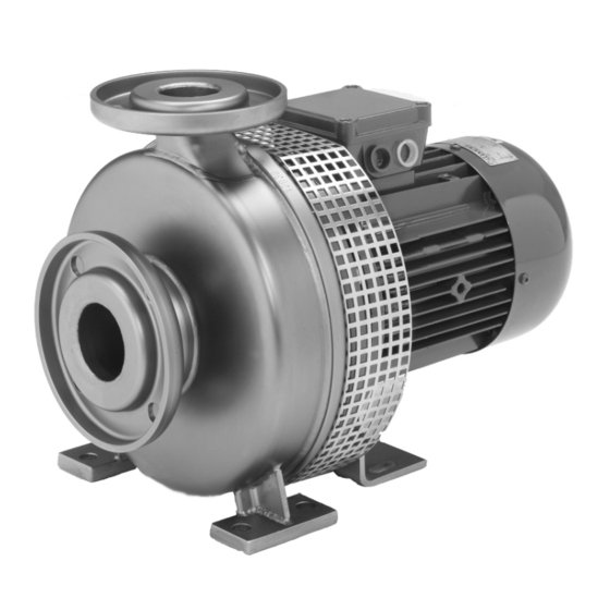
- Page 1 GEA Hilge MAXA BLOC Installation and operating instructions English Translation of the original operating manual 98412735-0417 GB engineering for a better world GEA Hilge...
- Page 2 Annex VII, Part B and we obligate to provide these upon reasoned request from the individual national authorities by data transfer. HILGE GmbH & Co.KG Authorized person for compiling and handing over Hilgestraße 37-47 technical documentation: 55294 Bodenheim, Germany Bodenheim, 2016-04-05 Franz Bürmann Managing Director GEA Hilge...
-
Page 3: Table Of Contents
English (GB) Installation and operating instructions Safety instructions The system used to identify safety instructions is described in Introduction section 2.3 on page 3. Target group Symbols and formatting 1.3 References to the document References to the document Copyright Safety This document may not be copied, translated into other Operator notes languages, or made available to third parties without our explicit... -
Page 4: Qualification And Training Of Personnel
• A: Failure to follow these safety instructions can endanger 2.5 Dangers caused by failure to follow the safety personnel. instructions • B: Safety instructions warning against electric voltage. If these safety instructions are not followed, employees, the pump • C: Failure to follow these safety instructions can endanger the and the environment will be in danger. -
Page 5: Improper Operation
2.9 Improper operation 2.12 Repair contract The operational reliability of the pump can be guaranteed only The duty to follow the legal regulations on work safety and the when it is used properly, as indicated in the relevant sections of regulations on environmental protection means that all the pump operating manual and the order papers. -
Page 6: Product Description
3. Product description 3.3 Proper usage Overview WARNING In this section you will get to know the pump as well as its design Improper usage! and application. The limits for application are described in the ▲ Death, serious bodily injury, damage to property. section "Technical data". - Page 7 3.4.2 Pump serial number 3.4.6 Weights The pump can be identified by the pump serial number. When Please note that, depending on design and accessories, the ordering spare parts, always state the pump serial number. weights may differ from those indicated. If presented with the pump/order number, the manufacturer can give you more precise 3.4.3 Nameplate information.
-
Page 8: Mounting, Installation And Connection
3.4.8 Maximum operating pressure 4.3 Installation in the pipeline WARNING WARNING Pressure overload! Mechanical overload! ▲ Death, serious bodily injury, damage to property. ▲ Death, bodily injury, damage to property. ► The pump must be operated according to the ► Do not use the pump or its connecting sleeves to order data. - Page 9 4.3.1 Operation of the mechanical seal 4.3.2 Reduction of noise and vibration Mechanical seals require a lubricating film in the sealing gap Noise and vibration are generated by the flow in pipes and which prevents contact between the two sliding surfaces. fittings.
-
Page 10: Connection Of Flushing System
4.4 Connection of flushing system 4.5 Electrical connections 4.4.1 Double mechanical seal WARNING HILGE pumps with double mechanical seal are equipped with a Electric shock! cartridge seal. ▲ Death, serious bodily injury. Depending on the seal design, the barrier or flushing liquid flows ►... -
Page 11: Start-Up / Shut-Down
5. Start-up / shut-down Please consider the following operating conditions if the pump is operated using a frequency converter: Overview This section describes how to start up and shut down the pump. Operating Actions You get to know which inspections contribute to failure-free conditions operation and increased life of the pump. -
Page 12: Shutting Down The Pump
5.2 Shutting down the pump WARNING Unintentional switching on of the pump! WARNING ▲ Death, bodily injury, damage to property. Pressure surge! ► Take appropriate measures to ensure that the ▲ Death, serious bodily injury, damage to property. pump cannot be unintentionally turned on again. ►... -
Page 13: Maintenance Of The Motor
6.3 Maintenance of the motor 6.3.1 Motors without lubrication fittings Motors without lubrication fittings are greased for life. The grease service lifetime is based on the bearing service lifetime. The prerequisite is that the motor is used according to catalogue specifications. -
Page 14: Assembly
6.4 Assembly DANGER Disregard of instructions! ▲ Death, bodily injury or damage to property. ► Before assembly or maintenance work of the pump, see section 6.1. 6.4.1 Parts overview, MAXA Valid for pump sizes 65-160/200/250. 0167.00 0433.00 0920.04 0934.00 0504.09 0902.02 0161.00 (0346.01)* 0412.00... - Page 15 6.4.2 Parts overview, MAXA Pump size 80-160. 0167.00 0433.00 0920.04 0934.00 0504.09 0902.02 0161.00 (0346.01)* 0412.00 0412.04 0930.00 0230.00 0922.00 0102.00 0236.00 Fig. 15 Parts overview Qty. Part no. Designation Qty. Part no. Designation 0102.00 Volute casing 0433.00 Mechanical seal 0161.00 Backplate (not applicable in Bloc version) 0504.09...
- Page 16 6.4.3 Bloc intermediate ring 0902.06 0934.06 0346.01 0686.01 0920.09 0183.00 0950.00 Fig. 16 Parts overview, bloc intermediate ring Qty. Part no. Designation Qty. Part no. Designation 0183.00 Supporting foot (up to motor size 112) 0920.09 Hexagon nut 0346.01 Intermediate ring 0934.06 Spring washer 0686.01...
- Page 17 6.4.4 Bloc motor 0802.00 0940.00 Fig. 17 Parts overview, Bloc motor Qty. Part no. Designation Qty. Part no. Designation 0802.00 Bloc motor 0940.00 6.4.5 Instructions for disassembly 6.4.6 Instructions for assembly DANGER DANGER Disregarding important instructions! Disregarding important instructions! ▲ Death, serious bodily injury, damage to property. ▲...
- Page 18 6.4.7 Single mechanical seal 6.4.8 Single mechanical seal with backplate liner Fig. 18 Single mechanical seal Parts overview 0167.00 - backplate liner Fig. 19 Single mechanical seal 0433.00 - mechanical seal Parts overview 0504.09 - spacer ring 0161.00 - backplate 0516.01 - locating ring.
- Page 19 6.4.9 Double mechanical seal, tandem 0167.00 0346.01 0491.00 0412.02 0433.00 0504.09 0433.01 0230.00 0412.83 Fig. 20 Double mechanical seal, tandem Parts overview 0167.00 - backplate liner 0230.00 - impeller 0346.01 - intermediate ring 0412.02 - O-ring 0412.83 - O-ring 0433.00 - mechanical seal 0433.01 - mechanical seal 0491.00 - cartridge seal 0504.09 - spacer ring.
- Page 20 6.4.10 Assembly of the impeller and volute casing 1. Insert the key 0940.00. 2. Grease the impeller seat and threaded pump shaft 0211.00. Use Klüberpaste UH1 96-402 from the HILGE assembly tool kit for this (pos. 6, fig. 35). MF-343 MF-583 Fig.
- Page 21 MF-575 MF-548 Fig. 29 Impeller nut Fig. 30 Spring of mechanical seal 11. Push the volute casing 0102.00 into the intermediate ring 12. Grease the studs 0902.02 at the volute casing. Use 0346.01. Klüberpaste UH1 96-402 from the HILGE assembly tool kit for this (pos.
-
Page 22: Troubleshooting
6.5 Troubleshooting Problem Cause Remedy 1. Incorrect electrical connection (two 1. Check the electrical connections and correct, if necessary. phases). 2. Reverse the phases of the power supply (reverse the polarity). 2. Wrong direction of rotation. 3. Vent the suction line or the pump and refill. 3. -
Page 23: Disposal
6.6 Disposal 1. Use the public or private waste collection service. 2. If this is not possible, contact the nearest GEA Hilge This product or parts of it must be disposed of in an company or service workshop. environmentally sound way: 6.7 HILGE assembly tool kit... -
Page 24: Certificate Of Non-Objection
7. Certificate of non-objection Overview This section contains a certificate of non-objection. In the event of inspection or repair send the pump including this certificate to HILGE. Certificate of non-objection The following pump and its accessories, together with this certificate of non-objection, are herewith contracted out by the undersigned for inspection/repair: Pump data •... - Page 28 Responsibility GEA-versity GEA Group is a global engineering company with multi-billion euro sales and operations in more than 50 countries. Founded in 1881, the company is one of the largest providers of innovative equipment and process technology. GEA Group is listed in the STOXX Europe 600 Index.
Need help?
Do you have a question about the Hilge MAXA BLOC and is the answer not in the manual?
Questions and answers