
Related Manuals for GEA Hilge NOVALOBE 60


Summary of Contents for GEA Hilge NOVALOBE 60
- Page 1 Hygienic Pumps GEA Hilge NOVALOBE 60 Operating instruction (Translation from the original language) 430BAL013312EN_1...
- Page 2 (print, photocopy, microfilm or another method) without the prior written permission of GEA Hilge Niederlassung der GEA Tuchenhagen GmbH hereinafter referred to as Manufacturer This restriction also applies to the drawings and diagrams included in the documentation. LEGAL NOTICE These instructions are part of the technical documentation, which is part of the scope of delivery.
- Page 3 – unintended operation and usage conditions, – insufficient maintenance, – improper operation, – incorrect installation, – incorrect or improper connection of electrical components. • resulting or arising from unauthorised modifications or failure to follow the instructions, • caused by use of accessories / spare parts that have not been supplied or recommended by the manufacturer.
- Page 4 SYMBOLS USED Danger Stands for an immediate danger which leads to heavy physical injuries or to the death. Warning! Stands for a possibly dangerous situation which leads to heavy physical injuries or to the death. Caution! Stands for a possibly dangerous situation which could lead to light physical injuries or to damages to property.
- Page 5 LAYOUT INFORMATION Bullet points and numbered list characters Bullet points are used to separate logical contents within a section: • Bullet point 1 Types of bullet point 1. • Bullet point 2 Types of bullet point 2. Numbered list characters are used to separate enumerations within a descriptive text: Descriptive text with consecutive numbering: –...
- Page 6 430BAL013312EN_1 20.09.2019...
-
Page 7: Table Of Contents
TABLE OF CONTENTS General Information about this document Manufacturer address Customer service EU Declaration of Conformity for Machines Safety Intended use 2.1.1 Pumped fluids Abrasive media Maximum particle size in the pumping medium 2.1.2 Connections and piping 2.1.3 Switching frequency 2.1.4 Types Safety precautions in these operating instructions... - Page 8 Checking the direction of rotation after connecting Earthing 6.3.6 Operation Principle Commissioning Special personnel qualification Safety instructions for commissioning Commissioning / initial startup 7.3.1 Checking conditions of use 7.3.2 Commissioning of the pump 7.3.3 Functional testing of the mechanical seal Cleaning Special personnel qualification Safety instructions...
-
Page 9: General
Types, technical data and spare part numbers are subject to technical change. We reserve the right to implement changes due to technical progress. Manufacturer address GEA Hilge Niederlassung der GEA Tuchenhagen GmbH Hilgestraße 37-47 55294 Bodenheim Germany Phone +49 6135 7016-0 Fax +49 6135 1737 hilge@gea.com... -
Page 10: Eu Declaration Of Conformity For Machines
EU Declaration of Conformity for Machines in accordance with the EC Machinery Directive 2006/42/EC, Annex II 1. A Manufacturer: GEA HILGE Niederlassung der GEA Tuchenhagen GmbH Hilgestrasse 37-47 D 55294 Bodenheim Germany We declare under our sole responsibility that the machine... -
Page 11: Safety
Safety Intended use Safety Intended use Warning! Non-intended use! ► Pump only media that are specified in the order. The pump has been specially designed for them. ► Operate the pump only on the electrical grid that was specified in the purchase order. -
Page 12: Types
Safety Safety precautions in these operating instructions 2.1.4 Types All information and descriptions in these operating instructions on the use and handling of the pumps refer exclusively to the standard versions. Special designs and customised deviations as well as random external influences in the use and operation are not included in these instructions. -
Page 13: Explanation Of The Safety Symbols Used
Safety Explanation of the safety symbols used Explanation of the safety symbols used Danger Stands for an immediate danger which leads to heavy physical injuries or to the death. ► Description to avert the danger Warning! Stands for a possibly dangerous situation which leads to heavy physical injuries or to the death. -
Page 14: Dangers Of Non-Compliance With Safety Information
Safety Unauthorised modification and ordering of spare parts Warning! Hazardous materials Contact with dangerous substances, e.g. by inhalation. ► Discharge the leakage of dangerous goods such that no danger to persons and the environment arises! ► Comply with legal provisions! ►... -
Page 15: Staff Qualifications And Training
Safety Staff qualifications and training Staff qualifications and training The staff for working on and with the pump must have the appropriate qualifications. Responsibilities, competencies and supervision of staff must be clearly defined by the operating company. If personnel do not have the necessary knowledge, they are to be trained and instructed. -
Page 16: Description
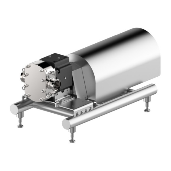
Description Pump overview Description Pump overview Fig.1: Schematic representation of NOVALOBE 60 Pump overview of NOVALOBE 10-50 Item Description Item Description Suction/discharge port Base frame Gear Oil inlet / oil outlet Coupling guard Display gear oil level Gear motor Suction/discharge port Description Pumps of the NOVALOBE series are rotary piston positive displacement pumps. -
Page 17: Pump Name
Nominal width BW: Bi-wing performance poles Operating point ML: Multilobe [kW] Nameplate GEA Hilge Niederlassung der GEA Tuchenhagen GmbH Hilgestrasse - D - 55294 Bodenheim Pump-Type: Ser.-No.: TAG No.: YOM: Made in Germany Fig.2: Nameplate Pump type: Pump name TAG No.:customer name... -
Page 18: Transport And Storage
Transport and Storage Special personnel qualification for transport and storage Transport and Storage Special personnel qualification for transport and storage Transports may only be carried out by qualified staff, who must observe the safety instructions. Safety precautions for transport and storage Warning! Danger from packaging material with sharp edges! ►... -
Page 19: Dimensions / Weights
Transport and Storage Dimensions / weights Storage of the pump Caution! Frost Risk due to external conditions. ► In case of frost risk, drain the pump completely. If the pump is not used immediately, proper storage conditions are as important for later operation as careful installation and proper maintenance. -
Page 20: Disposal Of Packaging Material
Transport and Storage Disposal of packaging material • After a longer storage period (more than 6 months), all elastomers (O-rings, shaft seals) must be checked for their elasticity. Brittle elastomers must be replaced. • Protect the pump from cold, moisture and dust, as well as from mechanical influences. -
Page 21: Technical Data
Technical data Serial number Technical data The operating safety of the delivered machine is only guaranteed if the machine is used as intended according to the sections of the operating instructions and the purchase order. Warning! Overload of the pump! ►... -
Page 22: Rotation Speed For O-Ring Seals
Technical data Rotation speed for O-ring seals – Application (speed, viscosity, etc.) The maximum differential pressure is specified on the nameplate. Rotation speed for O-ring seals The rotation speed of the O-ring seals is limited to ensure trouble-free operation. Please note the specified values. Hint! The maximum permissible speed depends on the nature of the pumped medium. -
Page 23: Assembly And Installation
Assembly and installation Safety precautions for setup, installation, and connection Assembly and installation Safety precautions for setup, installation, and connection Warning! Mechanical overload! ► Do not use the pump and its connection port as support for the pipeline. (EN 809 5.2.1.2.3 and EN ISO 14847). ►... - Page 24 Assembly and installation Safety precautions for setup, installation, and connection Caution! Vibration! ► Ensure stable construction for mounting of the pump and piping. Insufficiently stiffened substructures may cause an overall structure capable of oscillating, which is excited to oscillate by hydraulic and/or motor forces during changing operating conditions in the system.
-
Page 25: Special Personnel Qualification
The shaft must be rotatable without the rotors rubbing. If a rotor rubs against something, it has some damage that may have happened during transport of the pump. If the rotors rub: Contact the GEA Hilge service. If the rotors rotate freely: Reattach the coupling guard. -
Page 26: Installation In The Piping System
Assembly and installation Setup, installation, and connection Align the unit horizontally over the machined flat surfaces of the connecting pieces with a machine spirit level parallel to the motor axis. After aligning the unit, tighten the fastening screws evenly in a crosswise sequence (where applicable). -
Page 27: Space Requirements
Assembly and installation Setup, installation, and connection 6.3.3.2 Space requirements Maintain the following minimum distances. Pay attention to motor performance. 0.55 - 4 kW 300 mm 5.5 - 30 kW 300 mm Fig.6: Minimum distances (schematic representation) 6.3.3.3 Noise and vibration damping In NOVALOBE rotary piston pumps with base frame, the machine feet are equipped with dampening rubber. -
Page 28: Flushing Systems
Assembly and installation Setup, installation, and connection The flushing fluid has the task to lubricate and cool the product-side mechanical seal and the radial packing ring on the atmospheric side. The flushing fluid must meet the following criteria: • good flowability •... -
Page 29: Electrical Connection
Assembly and installation Setup, installation, and connection Single flushed seal: maximum 0.5 bar. Double seal: Pressure above the pump pressure as sealing liquid. Pressure under the pump pressure as sealing liquid. Close the return pipe (B). Check the strength of the connections. →... -
Page 30: Checking The Direction Of Rotation After Connecting
Assembly and installation Setup, installation, and connection Operation with frequency converter Operating Conditions Measures Install a dU/dt filter between the motor and frequency Noise-sensitive applications converter (reduces voltage spikes and thus noise). Particularly noise-sensitive applications Install sinusoidal filter. Use a cable which satisfies the conditions prescribed Cable length by the manufacturer of the frequency converter. -
Page 31: Operation Principle
Assembly and installation Earth the unit Equipotential bonding for the motor and pump is performed via the protective conductor connection in the terminal box. 6.3.6 Operation Principle Two precisely synchronised rotary pistons rotate in opposite directions. One in the clockwise direction the other in the counterclockwise direction. Due to the symmetrical shape of the rotors, the pump is suitable for operation in both directions. -
Page 32: Commissioning
Commissioning Special personnel qualification Commissioning Special personnel qualification The commissioning personnel must be suitably qualified for this work. See also Section 2.6, Page 15. Safety instructions for commissioning Warning! Danger by conveying against a closed shut-off valve. Rapid heating and sudden pressure increase. ►... -
Page 33: Functional Testing Of The Mechanical Seal
Commissioning If there is no increase of delivery head after commissioning: Switch off the pump. Again vent the pump (system). Repeat steps 7 to 10 and note section on Disruptions and Assistance for Disposal . 7.3.3 Functional testing of the mechanical seal Perform the following steps: Inspect the pump and check whether liquid exits at the mechanical seal. -
Page 34: Cleaning
Cleaning Special personnel qualification Cleaning To ensure the quality of sensitive fluids, pumps must be cleaned immediately after each use. Only in this way will adhesions and deposits be removed completely and contamination of the products be prevented. To achieve the best possible results, Hilge pumps are optimised with regard to gap and dead spaces, designed according to DIN EN 13951, and resistant to the cleaning agents referred to in the following chapter. -
Page 35: Cip
Cleaning Warning! Pressure shock by evaporating liquid! ► Completely empty the system before steam sterilisation. Notice Disposal of cleaning agents ► Dispose of cleaning agents properly and in an environmentally friendly way. CIP stands for Cleaning in Place, the pump is completely rinsed with cleaning agents. -
Page 36: Sip
Cleaning SIP stands for sterilisation in place, in which the pump is sterilised with superheated steam. For steam sterilization or sanitization, minimum temperatures of 121 ° C (250 ° F) must be applied to all wetted surfaces. The maximum permissible temperatures can be obtained from the section technical data. -
Page 37: Maintenance / Servicing
Maintenance / servicing Safety instructions for maintenance and servicing Maintenance / servicing Safety instructions for maintenance and servicing Warning! Improper execution of work! ► Maintenance and inspection should be carried out by authorised and qualified personnel. Warning! Danger from tilting / toppling over of the pump! ►... -
Page 38: Replacement Of O-Rings
Maintenance / servicing Pump maintenance 9.3.1.1 Replacement of O-rings Notice Hygiene risk, food safety Worn out and not fully functional components may lead to the contamination of the pump. ► Pay close attention to the condition of the O-rings during regular inspections. -
Page 39: Information On The Gear Unit Nameplate
Maintenance / servicing Maintenance of the motor – Shell Omala – Castrol Alphasyn – Mobil SHC 600 – Mobil 600 Hint! The type of oil used can be found in the order papers. 9.3.2.4 Information on the gear unit nameplate Fig.14: Nameplate (example) Gear motor nameplate... - Page 40 Maintenance / servicing Fig.15: Motor nameplate Nameplate designations 1 - QR code 13 - Permissible voltage range 3 - Number of phases 15 - Power factor 4 - Type designation 16 - Speed 5 - Order number/motor number 17 - Explosion protection code 6 - Year of manufacture 18 - Locked rotor current/rated current 7 - Thermal class insulation system...
-
Page 41: Malfunctions / Repairs
Malfunctions / repairs Special personnel qualification Malfunctions / repairs 10.1 Special personnel qualification The troubleshooting / repair personnel must be suitably qualified for this work. See also Section 2.6, Page 15. 10.2 Safety instructions Warning! Improper execution of work! ► Repair work should be carried out by authorised and qualified personnel. Danger Electric shock by touching live parts! ►... -
Page 42: Malfunctions And Remedies
Malfunctions / repairs Malfunctions and remedies Caution! Unsuitable tools! ► Make sure that all the parts can be mounted without damage. ► Use GEA Hilge assembly tools. 10.3 Malfunctions and remedies Actions for troubleshooting Malfunction Cause Remedy Pump does not Incorrect electrical connection (2 phases). -
Page 43: Repair
Malfunctions / repairs Repair Actions for troubleshooting Malfunction Cause Remedy Leakage in the Pump is strained (causing leaks at the pump body Install pump without strain, support piping by fixed pump body, the or at the connections). points. connections, the mechanical seal. - Page 44 Malfunctions / repairs Repair 430BAL013312EN_1 20.09.2019...
- Page 45 Malfunctions / repairs Repair Parts list NOVALOBE 60 Quantity Part no. Designation Quantity Part no. Designation 0101.01 Rotor housing 0580.08 0161.01 Cover 0580.09 0412.0B/0C O-ring 0818.01/02 Rotor 0412.54 O-ring 0870.01 Gearbox 0412.58/59 O-ring 0902.21 Stud screw 0412.99/0A O-ring 0904.18/19 Grub screw 0433.02/03 Mechanical seal 0906.01/02...
- Page 46 Malfunctions / repairs Repair 430BAL013312EN_1 20.09.2019...
- Page 47 Malfunctions / repairs Repair Parts list assembly NOVALOBE 60 Quantity Part no. Designation Quantity Part no. Designation 0840.00 Coupling 0901.86 Hex screw 0840.01 Coupling 0554.87 Washer 0867.02 Coupling insert 0901.85 Hex screw 0681.00 Coupling guard 0901.88 Hex screw 0592.17 Base 0554.88 Washer 0891.00...
-
Page 48: Parts Overview Motor Installation
Malfunctions / repairs Repair 430BAL013312EN_1 20.09.2019... - Page 49 Malfunctions / repairs Repair Parts list NOVALOBE 60 Pcs. Part no. Description Pcs. Part no. Description 0182.02 Foot 0560.12 0210.00 Output shaft 0560.20 0213.00 Drive shaft 0560.21 0328.00 Roller bearings 0560.22 0328.01 Roller bearings 0560.23 0328.02 Roller bearings 0560.24 0328.03 Roller bearings 0719.01 Hose...
-
Page 50: Installation Instructions
► Always replace mechanical seals completely. ► To tighten the rotor bolts 0906.01 / 02, use the original GEA-Hilge wrench and lock screw ► Check removed parts for damage and wear, and replace if necessary. -
Page 51: Seal Variants
Malfunctions / repairs Repair 10.4.6 Seal variants A: Single mechanical seal, B: Single mechanical seal, flushed, C: Single O-ring seal, D: Double mechanical seal 20 21 3 4 5 17 4 1 10 1112 14 15 Fig.19 17 - seal carrier 1 - slide ring (rotating) 9 -- O-ring (rinsed mechanical seal) -
Page 52: Disassemble Rotors And Mechanical Seals
Malfunctions / repairs Repair 10.4.7 Disassemble rotors and mechanical seals Tools and equipment: • Klüber paste UH1 96-402 • Klüber paste NH1 87-703 HYG • Pin extractor (slide hammer) M10, 0.9 kg • Puller for mechanical seals, 99027688 (service kit) •... - Page 53 Malfunctions / repairs Repair Remove the impeller screws (0906.01/02) with the O- rings (0412.0B/0C). Fig.25: Rotor bolt Remove the cover plate (0906.01/0554.86) and the O-rings (0412.58/59). Fig.26: Cover plate 0904.18/19 0560.26/27 Undo the two grub screws (0904.18/19) for about 2-3 turns - do not remove! Fig.27: Position of the dowel...
- Page 54 Malfunctions / repairs Repair Remove the grub screws. Fig.30: Set screws Remove the rotary rings (item 1) of the mechanical seals (0433.02/03) and remove the O-ring (pos 8). See Section 10.4.6, Page 51 Fig.31: Rotary ring of the mechanical seal Remove the o-ring (0412.99/0A).
-
Page 55: Install Mechanical Seals And Rotors
Unless stated otherwise, the parts listed in these instructions are shown in and Section 10.4.2, Page 44. The scope of delivery of the GEA Hilge spare mechanical seal includes a description with assembly instructions. Push the shaft sleeves (item 5) of the mechanical seals 0433.01/02 onto the shaft. - Page 56 Malfunctions / repairs Repair Press the package with a plastic mounting aid until the stop into the right position in the rotor housing. Fig.37: Seal carrier package Insert the O-ring (item 7) in the seal carrier (item 3). Fig.38: O-ring Install the set ring (item 10) with the mounting sleeve in the correct position.
- Page 57 Malfunctions / repairs Repair Grease the O-ring (item 8) with Klüber paste NH1 87- 703 HYG and insert in the rotor (0818.00/01). Fig.42: O-ring in rotor Press the rotary ring (item 1) into the correct position in the rotor. Pin and groove of the anti-rotation must fit over each other.
- Page 58 Malfunctions / repairs Repair Fix the rotor (0818.00/01) with the grub screws (0904.18). Use the lock screw for this. Torque: 70 Nm Fig.47: Grub screws and lock screw Insert the O-ring (0412.58/59) into the cover plate (0554.86). Fig.48: O-ring and cover plate Press the cover plate together with the O-ring into the rotor (0818.00/01).
-
Page 59: Torques For Assembly
Malfunctions / repairs Insert the O-ring (0412.54) into the groove of the black plate (0161.01). Fig.52: Housing cover with O-ring Mount the housing cover (0161.01) at the pump casing (0101.01). For this, use the lock washers (0930.23) and the cap nuts (0927.06). Fig.53: Back plate Tighten the cap nuts (0927.06). -
Page 60: Parts Overview Novalobe
→ The pump has been temporarily decommissioned. 11.4 Disposal Discard the pump or parts thereof in an environment-friendly manner: Use the service of public or private disposal companies. If this is not possible, contact the next GEA Hilge company or service centre. 430BAL013312EN_1 20.09.2019... -
Page 61: Appendix
Appendix Clearance certificate Appendix 12.1 Clearance certificate Von uns, der Unterzeichnerin, wird hiermit, gemeinsam mit dieser Unbedenklichkeitsbescheinigung, folgende Pumpe und deren Zubehör in Inspektions- / Reparaturauftrag gegeben: Angaben zur Pumpe • Typ: • Nr.: • Lieferdatum: Grund des Inspektions- / Reparaturauftrages: Die Pumpe (bitte ankreuzen) ___ wurde nicht in gesundheitsgefährdenden Medien eingesetzt. - Page 62 • GEA is a global technology company with multi-billion euro sales operations in more than 50 countries. Founded in 1881 the company is one of the largest providers of innovative equipment and process technology. GEA is listed in the STOXX ®...
Need help?
Do you have a question about the Hilge NOVALOBE 60 and is the answer not in the manual?
Questions and answers