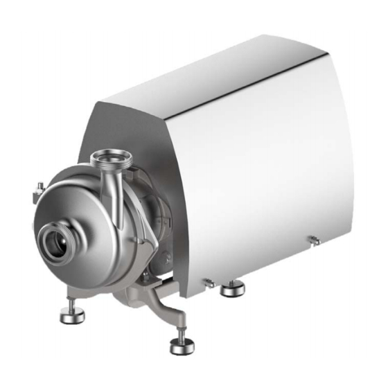
GEA Hilge HYGIA K Operating Instructions Manual
Hygienic pumps
Hide thumbs
Also See for Hilge HYGIA K:
- Operating manual (36 pages) ,
- Operating instruction (78 pages)

Related Manuals for GEA Hilge HYGIA K


Summary of Contents for GEA Hilge HYGIA K
- Page 1 Original instructions GEA Hilge HYGIA K Hygienic pumps GEA Hilge Niederlassung der GEA Tuchenhagen GmbH BA.H2A.KYY.001.GB_4 09.2023 / Revision: 1 / Language: English GEA.com...
- Page 2 Copyright © GEA Hilge, subsidiary of GEA Tuchenhagen GmbH 2023. All rights reserved. No liability will be accepted for damage resulting from non-observance of this document. If you have any questions or require clarification concerning the use of this document, Customer service .
-
Page 3: Table Of Contents
Table of Contents - 3 / 94 Table of Contents 1 General Information about the document 1.1.1 Purpose and structure of the document 1.1.2 Design elements 1.1.3 Reading obligation and storage 1.1.4 Respective documents Manufacturer address Customer service Declarations of conformity 2 Safety Intended use 2.1.1... - Page 4 4 / 94 - Table of Contents 3 Description Set-up and function 3.1.1 Component overview 3.1.2 Structure and quality Areas of application Hygienic design applications Pump denomination Signs Protective devices Technical data 3.4.1 Type plate 3.4.2 Weights 3.4.3 Torques 3.4.4 Serial number 3.4.5 Performance specifications...
- Page 5 Table of Contents - 5 / 94 6 Commissioning Preparing commissioning Operating conditions Initial start-up Restarting Monitoring operation Shutdown 7 Cleaning General points CIP cleaning Cleaning at standstill 8 Maintenance Maintenance and inspection 8.1.1 Maintenance jobs Disassembly 8.2.1 Removing the shaft sleeve Assembly 8.3.1 Installation instructions...
-
Page 6: Table Of Contents
6 / 94 - Table of Contents 0000000074 - 001 - EN-GB... -
Page 7: General
This chapter contains basic instructions on the use of this document and explanations of typographical conventions. In addition, this chapter contains details on the version and structure. In this document, the term pump refers to GEA Hilge HYGIA K. 1.1 Information about the document 1.1.1 Purpose and structure of the document The purpose of this Operating Manual is to convey information on operation of the pump. -
Page 8: Reading Obligation And Storage
External documents ● Operating manual for motor The documents named are not part of this Operating Manual. Documents which are not available can be requested from GEA Hilge. 1.2 Manufacturer address GEA Hilge, subsidiary of GEA Tuchenhagen GmbH Hilgestrasse 37-47... -
Page 9: Declarations Of Conformity
1.4 Declarations of conformity - 9 / 94 1.4 Declarations of conformity... - Page 10 Designation: Centrifugal pump Model / type: GEA Hilge HYGIA I ADAPTA, ADAPTA-SUPER GEA Hilge HYGIA II ADAPTA, ADAPTA-SUPER GEA Hilge HYGIA I K, K-SUPER GEA Hilge HYGIA II K, K-SUPER conforms with all the relevant provisions of this directive and the following directives: Relevant EC directives: 2006/42/EC –...
- Page 11 1.4 Declarations of conformity - 11 / 94...
- Page 12 12 / 94 - 1.4 Declarations of conformity 0000000074 - 001 - EN-GB...
-
Page 13: Safety
GEA Hilge. Modifications can endanger the operating safety and lead to personal inju- ries and property damage. Exclusive use of original spare parts and accessories author- ised by GEA Hilge ensures safety. The manufacturer will bear no liability for consequen- ces arising from the use of unauthorised parts. -
Page 14: Structure Of Warning Notices
14 / 94 - 2.3 Structure of warning notices 2.3 Structure of warning notices Warning notices warn of hazards which can occur when certain actions are carried out. The warning notices described below are used in this document. The extent of hazards is classified in risk levels and can be recognised by the respective signal words. -
Page 15: Personnel Qualification
The groups of people named below must also have the personnel qualifications or skills listed below and be authorised for actions at the pump by the operator. operating staff ● Instructed by the operator, a trained customer specialist or a GEA service specialist customer specialist ● Technical training trained customer specialist ●... -
Page 16: Mechanical Hazard
16 / 94 - 2.5 General safety instructions 2.5.2 Mechanical hazard Source Consequences Measures Moving or rotating components Being drawn in or caught Remove jewellery. ● ● ● Entrapment ● Tie hair back or wear a hair Crushing net. ● Impact Wear tight-fitting clothing. -
Page 17: Thermal Hazard
2.5 General safety instructions - 17 / 94 2.5.4 Thermal hazard Source Consequences Measures Objects or materials at high or Freezing Wear personal protective ● ● low temperature Burns gear. ● Scalding Wait for adjustment to room ● ● temperature. Radiation from heat sources Burns Wear personal protective... -
Page 18: Hazard Due To Operating Environment
● ing cycle. 2.6 Personal protective equipment To prevent possible personal injuries, the personal protection equipment must be worn. In addition, GEA recommends keeping the requirements listed below. ● Locally applicable accident prevention regulations ● Instruction manual from the operator or employer... -
Page 19: Safety Devices
2.7 Safety devices - 19 / 94 2.7 Safety devices Safety devices monitor operating parameters. To protect the pump, measures are initi- ated automatically if the specified tolerance values are exceeded. If one of the safety devices triggers stopping of the pump, the pump may only be re- started after the cause has been determined and eliminated. -
Page 20: Emergency Measures
20 / 94 - 2.10 Emergency measures 2.10 Emergency measures If an emergency occurs at the pump, the company regulations must be followed and the measures listed below must be taken. Fire ● Call local experts ● Use extinguishing equipment according to company regulations ●... -
Page 21: Description
3.1 Set-up and function - 21 / 94 3 Description This chapter contains descriptions of the set-up and function of the pump. 3.1 Set-up and function 3.1.1 Component overview HYGIA K 0340 0156 0801 0103 0153 0180 Figure 3-1 - Overview diagram of the components Position Designation Position... -
Page 22: Areas Of Application
Pumps used for hygienic applications must have certain equipment features and are configured accordingly when ordered. Execute connections in accordance wit the “EHEDG White Paper on GFSI Hygienic Design Scope”. 3.1.2.3 Pump denomination GEA Hilge HYGIA 40/40 Pump name Size Design type... -
Page 23: Signs
3.2 Signs - 23 / 94 3.2 Signs Overview and layout All safety signs and labels must meet the following criteria during the entire life span of the pump: ● Complete ● Attached as illustrated ● Clean and legible Figure 3-2 - Overview diagram of the signs on the pump Position Description Position Description Nameplate... -
Page 24: Protective Devices
24 / 94 - 3.3 Protective devices 3.3 Protective devices The motor stool is equipped with two safety plates to guard the shaft connection. 3.4 Technical data 3.4.1 Type plate Each pump carries a nameplate. For information about exact positioning, see chapter 3.2 Signs . - Page 25 3.4 Technical data - 25 / 94 112M 62.3 69.3 65.8 64.5 77.9 74.4 69.6 74.4 70.9 132S 84.7 91.7 88.2 86.9 98.5 103.3 99.8 81.8 78.3 Weight [kg] HYGIA II K (1) 100L 60.5 59.2 70.7 75.85 100L 68.5 67.2 78.7 83.85...
-
Page 26: Torques
26 / 94 - 3.4 Technical data 160M 134.8 18.5 160L 154.8 160L Weight [kg] HYGIA II K (2) 100L 63.8 68.6 65.1 100L 67.3 72.1 68.6 100L 60.8 65.6 62.1 112M 83.5 79.8 84.6 81.1 112M 80.5 72.8 77.6 74.1 132S 92.8... -
Page 27: Serial Number
3.4 Technical data - 27 / 94 Element Part num- Assembly location Thread / torque Hexagon nut 0920.04 Back plate M10 / 35 Nm Hexagon nut 0920.09 Motor stool M10 / 35 Nm M12 / 65 Nm M16 / 100 Nm M10 / 20 Nm Impeller nut 0922.00... -
Page 28: Operating Temperatures
28 / 94 - 3.4 Technical data 3.4.7 Operating temperatures 3.4.7.1 Maximum media temperatures Design Temp. [°C] Normal version Sterilisation (SIP) Further temperatures on request. 3.4.7.2 Ambient temperatures Permissible ambient temperatures Minimum temperature Maximum temperature 0 °C 40 °C 3.4.8 Maximum operating pressure The pump’s maximum operating pressure pump depends on various factors: ●... -
Page 29: Resistance Of Sealing Materials
These can only be determined by the user. If necessary, GEA Hilge can support you with further information for special applications. -
Page 30: Minimum Flow Rate
30 / 94 - 3.4 Technical data Medium Temperature Gasket material (general operating temperature) Product with a fat con- tent of max. 35% Product with a fat con- – tent of more than 35% Oils – 3.4.10 Minimum flow rate Minimum flow rate depending on pump type and speed Pump type Speed [rpm]... -
Page 31: Storage And Transport
If stored for longer than three months: check the general condition of all parts and package regularly. INFO After a storage period of more than three years: contact GEA Hilge to have the pump repaired again. 4.2 Transport aids If the weight of the pump exceeds 40 kg, transport may only be by crane or forklift truck. - Page 32 32 / 94 - 4.3 Transport Unpacking the pump Prerequisites The pump is in a box on a wooden pallet. ● The packaging is undamaged. ● Tools Scissors or knife ● Gloves ● Strap, load lifting equipment with sufficient load-bearing capacity. ●...
-
Page 33: Assembly And Installation
5.1 Requirements on the place of use - 33 / 94 5 Assembly and installation This chapter contains information and instructions for the assembly and installation of the pump. The target group for this chapter are all those who carry out actions at the pump in this context. - Page 34 34 / 94 - 5.1 Requirements on the place of use Operator-side measures electrical connection ● Have the electrical connections be made by a licensed electrician. ● Follow the VDE as well as local regulations, in particular the safety regulations. ●...
-
Page 35: Reducing Noises And Vibration
5.1 Requirements on the place of use - 35 / 94 5.1.1 Reducing noises and vibration Foundation and vibration absorbers To achieve optimum performance and to minimize noise and vibration, it is recommen- ded to provide the pump with vibration absorbers. In general, this should always be considered for pumps with motor sizes starting from 11 kW (15 hp). - Page 36 36 / 94 - 5.1 Requirements on the place of use Compensators If the pump is mounted on a foundation along with vibration absorbers, be sure to in- stall compensators at the pipe connections. This prevents the pump from “hanging” in the connections.
-
Page 37: Assembly Preparations
Carefully rotate the shaft of the impeller. The shaft should be easy to rotate. If the impeller rubs against something, it has some damage that may have happened during transport of the pump. If the impeller rubs, contact GEA Hilge Customer Service. -
Page 38: Set-Up, Assembly, Connection
38 / 94 - 5.3 Set-up, assembly, connection 5.3 Set-up, assembly, connection Setting up and aligning Responsibility ● Customer specialist Prerequisites 5.1 Requirements on the place of use are fulfilled. ● Tools Machine spirit level ● Spanner ● Fastening material (if appropriate) ●... -
Page 39: Installation In The Piping System
5.3 Set-up, assembly, connection - 39 / 94 5.3.1 Installation in the piping system Installation in the piping system Responsibility ● Customer specialist Prerequisites The pump is free of packaging material. ● Transport covers have been removed from suction port and discharge port. ●... -
Page 40: Quench Version (Optional)
40 / 94 - 5.3 Set-up, assembly, connection 5.3.2.1 Quench version (optional) Pre-requisites for quench operation HILGE pumps with quench seal are equipped with a lip seal. The pressureless flushing fluid is located between the mechanical seal and the lip seal. The following conditions must be fulfilled for quench operation: ●... - Page 41 5.3 Set-up, assembly, connection - 41 / 94 Connecting quench flushing (optional) Responsibility ● Customer specialist Prerequisites Connections for connecting the flushing are fulfilled. ● Tools Spanner ● Connect the discharge line (A). Figure 5-6 - Connections for flushing Position Description Discharge line Feed line Connect the feed line (B).
-
Page 42: Connecting The Pump To The Power Supply
42 / 94 - 5.3 Set-up, assembly, connection Requirements on the flushing fluid The flushing fluid has the task to lubricate and cool the product-side mechanical seal and the shaft seal on the atmospheric side. The flushing fluid must meet the following criteria: ●... - Page 43 5.3 Set-up, assembly, connection - 43 / 94 Earthing the machine pad support Prerequisites The pump is ready for connection. ● Tools Toothed lock washer ● Earth cable ● Spanner ● Screw the earth cable to position (B). Use a toothed lock washer. Figure 5-7 - Connection for the earth cable Connect the earth cable to the earth conductor.
- Page 44 44 / 94 - 5.3 Set-up, assembly, connection Earthing the motor shroud Prerequisites The pump is ready for connection. ● Tools Toothed lock washer ● Earth cable ● Spanner ● Use the bore hole (A) provided to con- nect the earth cable on the side of the motor shroud.
- Page 45 5.3 Set-up, assembly, connection - 45 / 94 Connecting the pump to the power supply Responsibility ● Trained customer specialist Prerequisites Conditions for connecting the pump to the power supply are fulfilled. ● The pump has been earthed in accordance with the specifications in this oper- ●...
-
Page 46: Connecting Frequency Inverter
46 / 94 - 5.3 Set-up, assembly, connection Checking the direction of rotation after connecting Responsibility ● Trained customer specialist Prerequisites The pump has been connected to the power supply. ● All safety devices have been installed. ● All hydraulic connections have been checked for a firm fit. ●... - Page 47 5.3 Set-up, assembly, connection - 47 / 94 Operating conditions Measures Supply voltage up to 500 V Check that the motor is suitable for frequency converter operation. Supply voltage between 500 V and 690 V Install a dU/dt filter between the motor and the frequency converter (reduces voltage peaks and thus noise), or check whether the motor has a re- inforced insulation.
- Page 48 48 / 94 - 5.3 Set-up, assembly, connection 0000000074 - 001 - EN-GB...
-
Page 49: Commissioning
6.1 Preparing commissioning - 49 / 94 6 Commissioning This chapter contains information for initial start-up and every recurring start-up of the pump. In addition, this chapter describes the checks and tests to be performed during this. The target group for this chapter are all those who carry out actions at the pump in this context. -
Page 50: Initial Start-Up
50 / 94 - 6.3 Initial start-up 6.3 Initial start-up Initial start-up of the pump Responsibility ● Operating staff Prerequisites All connections have been checked for a firm fit. ● All safety devices have been installed. ● The electrical connections are correct. ●... -
Page 51: Restarting
6.4 Restarting - 51 / 94 Function test of the shaft seal (quench) INFO An intact shaft seal effectively separates the pumped liquid from the flush- ing liquid. If there is pumped medium in the flushing liquid, switch the pump off and replace the shaft seal (have the shaft seal replaced). Responsibility ●... -
Page 52: Shutdown
52 / 94 - 6.6 Shutdown 6.6 Shutdown Shutdown Responsibility ● Operating staff Prerequisites The pump and valves are freely accessible. ● CAUTION Pressure surge A pressure surge can cause damage to the pump and system. Always close shut-off valves slowly. ●... -
Page 53: Cleaning
7.1 General points - 53 / 94 7 Cleaning This chapter contains information about cleaning the pump. In addition, this chapter provides information about cleaning intervals and the use of cleaning agents. The tar- get group for this chapter are all those who carry out actions related to cleaning at the pump. -
Page 54: Cleaning At Standstill
54 / 94 - 7.3 Cleaning at standstill Cleaner Chemical Max. con- Max. tem- Permissible Max. per- Max. per- type designa- centration perature missible Cl missible tion [°C] (°F) content in contact the prepa- time ration wa- [mg/l] Acid C2H4O3 0.01% 90 (194) Acid... -
Page 55: Maintenance
8.1 Maintenance and inspection - 55 / 94 8 Maintenance This chapter contains information about the maintenance, inspection and repairs of the pump. The target group for this chapter are all those who carry out actions at the sys- tem in this context. 2 Safety of this document. - Page 56 56 / 94 - 8.1 Maintenance and inspection To prevent any faults and guarantee maximum operational safety of the pump, GEA recommends the following inspection and maintenance work. Hygiene risk, food safety Worn out and not fully functional components may lead to the contami- nation of the pump.
-
Page 57: Maintenance Jobs
8.1 Maintenance and inspection - 57 / 94 8.1.1 Maintenance jobs Replace O-rings INFO The O-rings should be replaced every time the pump is disassembled. Prerequisites Access to the pump ● The pump is at a standstill and secured against restart. ●... -
Page 58: Disassembly
The pump has been secured against being switched on unintentionally. ● If hazardous media have been pumped, the pump has been decontaminated. Tools from the GEA Hilge assembly tool kit make disassembly easier and avoid damage 59 . to the pump, see page 8.2.1 Removing the shaft sleeve... -
Page 59: Assembly
8.3 Assembly - 59 / 94 8.3 Assembly Assembly tool kit Tools from the GEA Hilge assembly tool kit prevent damage to the mechanical seal dur- ing assembly. Figure 8-1 - Tools in the GEA Hilge assembly tool kit Contents and use... - Page 60 60 / 94 - 8.3 Assembly Image Designation GEA Hilge HYGIA I GEA Hilge HYGIA II position Plastic adapter Ø 28 ● Mechanical seal mounting sleeve Ø 19 and ● Ø 22 Plastic adapter Ø 19 ● T-handle with 1/2” square ●...
- Page 61 8.3 Assembly - 61 / 94 Parts overview pump part 0161.00 0902.02 0901.07 0412.00 0412.04 0927.00 0230.00 0934.03 0930.00 0433.00 0922.00 0557.00 (*2) 0412.05 (*2) 0103.00 0920.00 0421.06 (*1) 0554.00 0932.09 (*1) 0501.00 0412.00 0902.02 0161.00 0412.04 0230.00 0901.32 (*1) 0491.00 (*1) 0412.02 (*1) 0433.00...
- Page 62 62 / 94 - 8.3 Assembly Pcs. Part num- Designation Pcs. Part num- Designation 0491.00 Seal cartridge 0930.00 Toothed lock washer 0501.00 Clamp ring 0932.09 Retaining ring 0501.01 Clamp ring 0934.03 Spring washer 0000000074 - 001 - EN-GB...
- Page 63 8.3 Assembly - 63 / 94 Parts overview for K motor stool 0736.04 (*1) 0731.30 (*1) 0346.00 0970.00 0930.18 1000.11 0686.02 0914.05 0554.74 0901.50 0686.01 0920.04 0554.73 0340.00 0731.31 (*1) 0736.05 (*1) Figure 8-3 - Parts overview for K motor stool Pcs.
- Page 64 64 / 94 - 8.3 Assembly Parts overview of drive 0970.01 0970.03 0801.00 (*4) 0940.03 0515.06 0211.00 0940.00 0920.09 0554.75 0515.06 0930.02 0901.49 Figure 8-4 - Overview of the drive parts Pcs. Part num- Designation Pcs. Part num- Designation 0211.00 Shaft 0901.49 Hex head screws...
- Page 65 8.3 Assembly - 65 / 94 Pcs. Part num- Designation Pcs. Part num- Designation 0680.00 Motor shroud 0970.01 Rotation arrow 0801.00 Motor 0970.02 Rotation arrow 0901.02 Hex screw 0970.03 Warning label / informa- tion label Parts overview motor shroud Figure 8-5 - Parts overview motor shroud Pcs.
-
Page 66: Installation Instructions
66 / 94 - 8.3 Assembly Pcs. Part no. Designation Pcs. Part no. Designation 0592.13 Base 0920.81 Hexagon nut 0595.00 0927.08 Cap nut 0680.00 Motor shroud 8.3.1 Installation instructions INFO Contaminated components will contaminate the pump and system. Use suitable chemical cleaning agents to remove impurities in the area of the impeller area, the O-rings or the mechanical seal. -
Page 67: Installing Shaft Sleeve
8.3 Assembly - 67 / 94 8.3.2 Installing shaft sleeve Responsibility ● Customer specialist Prerequisites Applies to the flushed mechanical seal, quench. ● The shaft sleeve is used to repair a worn pump shaft, using the original seal ● size. The pump has been disassembled. - Page 68 68 / 94 - 8.3 Assembly Lightly grease the surface with Klüber paste and fit the seal (see manufactur- er’s operating manual in the assembly set). Figure 8-7 - Drive the sleeve with light blows from the mallet onto the shaft Position Description Hammer Mounting sleeve...
-
Page 69: Installing The Motor, Motor Stool And Pump Shaft
8.3 Assembly - 69 / 94 8.3.3 Installing the motor, motor stool and pump shaft Installing the motor, motor stool and pump shaft Responsibility ● Trained customer specialist Prerequisites The pump has been disassembled. ● Tools Klüber paste UH1 96-402 ●... - Page 70 70 / 94 - 8.3 Assembly 4. INFO The work steps 4 to 12 show the as- sembly of the flushed mechanical seal. For versions with a single me- chanical seal (without seal cartridge), continue from work step 13. Wet lip seal (0421.06) with water and push into seal...
- Page 71 8.3 Assembly - 71 / 94 Grease hex head screws (0901.32) with Klüber paste and connect the seal cartridge (0491.00) with the back plate (0161.00). Note the torques on 26 . page Wet set screws (0902.02) with Loctite 243 and screw them into the back plate (0161.00) up to the stop.
- Page 72 72 / 94 - 8.3 Assembly Wet the other threads of the pipes (0736.04) and (0736.05) with Loctite 243 (medium strength) and connect it with the seal cartridge (0491.00). Grease the centring for holding the motor stool at the motor flange and grease the screw connection with Klüber paste.
- Page 73 8.3 Assembly - 73 / 94 Screw on the impeller nut (0922.00) without the O-ring seal and tighten. This sets the correct length of the shaft. Tighten head screws (0901.49) of the clamp connection in a crosswise sequence. Note the tor- 26 .
-
Page 74: Determining The Gap Size
74 / 94 - 8.3 Assembly 8.3.4 Determining the gap size Gap size 0412.00 0161.00 0230.00 0103.00 0211.00 0922.00 0557.00 0412.05 Figure 8-9 - Cutaway view HYGIA with HPM casing The gap size needs to be determined only if modifying/replacing the impeller or the ring housing. - Page 75 8.3 Assembly - 75 / 94 is not necessary to determine the gap size. Such pumps have a larger gap by design, which does not have to be adjusted exactly. Determining the gap size - pump with conical spring mechanical seal Responsibility ●...
- Page 76 76 / 94 - 8.3 Assembly Determining the gap - pump with conical spring mechanical seal Responsibility ● Trained customer specialist INFO Determination of the air gap (a or a‘) for pumps with encapsulated me- chanical seal. Prerequisites The key (0940.00) has been removed. ●...
-
Page 77: Installing Single Mechanical Seal
Installing single conical spring mechanical seal Responsibility ● Trained customer specialist Prerequisites The pump has been disassembled. ● Tools Equipment and tools from the GEA Hilge assembly tool kit ● Spray bottle ● Plastic mounting sleeve ● Mounting sleeve ●... - Page 78 78 / 94 - 8.3 Assembly Push the mounting sleeve onto the shaft shoulder. Moisten the mounting sleeve with clean water. Push the rotating unit of the mechani- cal seal (0433.00) in the assembled state onto the shaft (0211.00) as far as it will go.
-
Page 79: Installing The Single Encapsulated Mechanical Seal
Responsibility ● Trained customer specialist Prerequisites The pump has been disassembled. ● Tools Equipment and tools from the GEA Hilge assembly tool kit ● Spray bottle ● Plastic mounting sleeve ● INFO HILGE assembly tools prevent damage to the mechanical seal during as- sembly. -
Page 80: Install Impeller
8.3.7 Install impeller Install impeller Responsibility ● Trained customer specialist Prerequisites The mechanical seal has been installed. ● Tools Equipment and tools from the GEA Hilge assembly tool kit ● Klüber paste UH1 96-402 ● Extractor ● Spray bottle ● Socket wrench ●... - Page 81 Grease the thread of the impeller nut (0922.00) with Klüber paste. 6. INFO Only use original lock washers from GEA Hilge to fasten the impeller and replace them after they have been reused five times. Grease lock washer (0930.00) with Klüber paste.
- Page 82 82 / 94 - 8.3 Assembly Grease lock washers as shown. 0922.00 0412.04 0230.00 Position Description (0230.00) impeller | (0412.04) O-ring (0922.00) Impeller nut (A) Fine gearing - greased (B) Coarse gearing against each other - greased Insert the lock washers (0930.00) into the impeller nut (0922.00).
- Page 83 8.3 Assembly - 83 / 94 Wet the O-ring (0412.04) with water and use the impeller nut (0922.00) to push it into the gap between the im- peller nut (0922.00) and the impeller (0230.00). ATTENTION Danger through surface damage Damaged and scratched surfaces can cause contamination and endan- ger food safety.
-
Page 84: Installing Pump Casing
Installing KLM pump casing Responsibility ● Trained customer specialist Prerequisites The impeller has been installed. ● Tools Equipment and tools from the GEA Hilge assembly tool kit ● Klüber paste UH1 96-402 ● Plastic hammer ● Spray bottle ● Machine spirit level ●... - Page 85 8.3 Assembly - 85 / 94 Note the direction specification on the clamp ring and install the upper and lower clamp ring (0501.00 / 0501.01). Tighten the tie bolt (0905.00), the washer (0554.00) and the hexagon nut (0920.00) only handtight. Align the annular casing (0103.00) via the pressure piece using a mechanic’s spirit level.
- Page 86 Responsibility ● Trained customer specialist Prerequisites The impeller has been installed. ● Tools Equipment and tools from the GEA Hilge assembly tool kit ● Spray bottle ● Spanner ● INFO HILGE assembly tools prevent damage to the mechanical seal during as- sembly.
-
Page 87: Faults
9.1 Faults and remedies - 87 / 94 9 Faults This chapter contains information about handling faults at the pump. In addition, it de- scribes the personnel qualifications required for the individual actions. It addresses all those who carry out actions at the pump in this context. INFO For all troubleshooting, observe chapter 2 Safety in this operating manual. - Page 88 88 / 94 - 9.1 Faults and remedies Malfunction Possible cause Measure Motor protection switch is not Check the setting, replace the set properly motor protection switch if neces- sary. Motor runs on 2 phases. Check electrical connection, re- place defective fuse. Pump causes too much noise.
- Page 89 9.1 Faults and remedies - 89 / 94 Malfunction Possible cause Measure Impermissible temperature in- Air in suction line or pump. Suc- Vent and prime suction pipe or creases at pump, bearing hous- tion head too high, NPSH system pump. Raise suction side liquid ing or motor.
- Page 90 90 / 94 - 9.1 Faults and remedies 0000000074 - 001 - EN-GB...
-
Page 91: Decommissioning, Dismantling And Disposal
10.1 Decommissioning - 91 / 94 10 Decommissioning, dismantling and disposal This chapter contains information about decommissioning the pump and describes dis- mantling and disposal. The target group for this chapter are all those who carry out ac- tions at the machine in this context. This chapter contains information about decommissioning and disposing of the pump. -
Page 92: Disposal
92 / 94 - 10.3 Disposal 10.3 Disposal Dispose of the pump in an environmentally friendly way. Observe the statutory waste disposal regulations applicable at the place of installation. The pump consists of the following materials: ● Metals ● Synthetic materials ●... -
Page 93: Annex
11.1 Clearance certificate - 93 / 94 11 Annex 11.1 Clearance certificate Clearance certificate Certificate Your specifications We, the undersigned, together Pump specifications Reason for inspection/repair or- with this clearance certificate der: hereby order the following Type: pump and its accessories to be inspected/repaired: Pump number: Delivery date:... - Page 94 GEA Hilge Niederlassung der GEA Tuchenhagen GmbH Hilgestraße 37 – 47 55294 Bodenheim, Germany Tel +49 6135 7016-0 © GEA Hilge. All rights reserved. Subject to modifications. Printed in Germany.
Need help?
Do you have a question about the Hilge HYGIA K and is the answer not in the manual?
Questions and answers