
Subscribe to Our Youtube Channel
Related Manuals for GEA Hilge HYGIA ADAPTA


Summary of Contents for GEA Hilge HYGIA ADAPTA
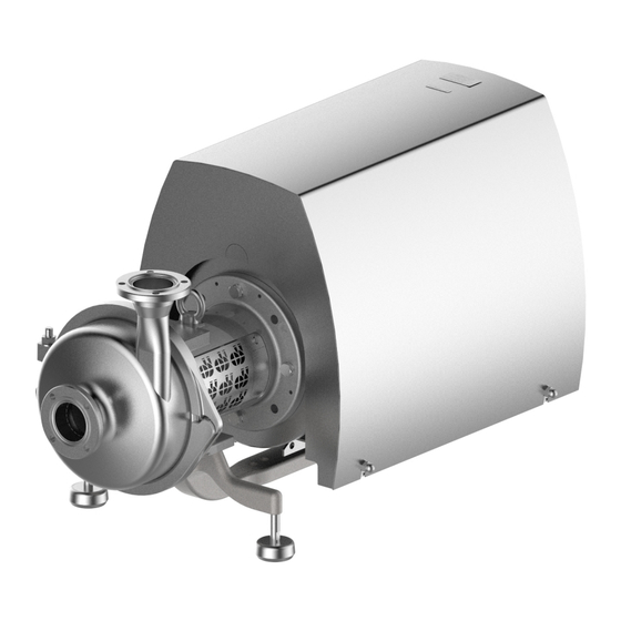
- Page 1 OperatIng InstructIOns Translation of the original instructions GEA Hilge HYGIA ADAPTA Hygienic pumps GEA Hilge Dokumentnummer: BA.H2A.ADY.001 Version: 001 / Sprache: EN-GB / Datum: 15.03.2024 GEA.com PUBLIC...
- Page 2 Copyright © GEA Hilge, subsidiary of GEA Tuchenhagen GmbH 2024. All rights re- served. No liability will be accepted for damage resulting from non-observance of this document. If you have any questions or require clarification concerning the use of this...
-
Page 3: Table Of Contents
Hazard due to operating environment 2.5.9 Ergonomic hazard 2.5.10 Hazard through hazardous substances Personal protective equipment Safety devices Residual Hazards Safety signs 2.10 Emergency measures Copyright @ GEA Hilge PUBLIC BA.H2A.ADY.001 - EN-GB 2024 - All rights reserved 0000014899 - Rev001 - 15.03.2024... - Page 4 5.3.2.1 Double mechanical seal (optional) 5.3.3 Connecting the pump to the power supply 5.3.3.1 Operator-side pre-requisites equipotential bonding 5.3.3.2 Connecting frequency inverter BA.H2A.ADY.001 - EN-GB PUBLIC Copyright @ GEA Hilge 0000014899 - Rev001 - 15.03.2024 2024 - All rights reserved...
- Page 5 Installing the single encapsulated mechanical seal 8.3.8 Installing double mechanical seal 8.3.9 Install impeller 8.3.10 Installing pump casing 8.3.11 Installing the safety guards Malfunctions Faults and remedies Copyright @ GEA Hilge PUBLIC BA.H2A.ADY.001 - EN-GB 2024 - All rights reserved 0000014899 - Rev001 - 15.03.2024...
- Page 6 Table of Contents 6/120 Decommissioning, dismantling and disposal 10.1 Decommissioning 10.2 Dismantling 10.3 Disposal Annex 11.1 Clearance certificate 11.2 Abbreviations and terms BA.H2A.ADY.001 - EN-GB PUBLIC Copyright @ GEA Hilge 0000014899 - Rev001 - 15.03.2024 2024 - All rights reserved...
-
Page 7: General
This chapter contains basic instructions on the use of this document and explanations of typographical conventions. In addition, this chapter contains details on the version and structure. In this document, the term pump refers to GEA Hilge HYGIA ADAPTA. 1.1 Information about the document 1.1.1 Purpose and structure of the document The purpose of this Operating Manual is to convey information on operation of the pump. -
Page 8: Reading Obligation And Storage
Operating manual for mounted components, such as motor, coupling, discharge valve, flushing container The documents named are not part of this Operating Manual. Documents which are not available can be requested from GEA Hilge. 1.2 Manufacturer address GEA Hilge, subsidiary of GEA Tuchenhagen GmbH... - Page 9 Annex VII, Part A, and agree to submit the documentation on justified request of national authorities on a data carrier. Person authorised for compilation and handover of GEA HILGE technical documentation: Subsidiary of GEA Tuchenhagen GmbH Hilgestrasse 37-47 55294 Bodenheim Germany Bodenheim, ....Signature Signature...
-
Page 10: Ukca Declaration Of Conformity
1.4.2 UKCA Declaration of Conformity Declaration of Conformity The following declaration does not contain serial numbers or signatures. The original declaration is delivered with the pump. GEA HILGE Subsidiary of GEA Tuchenhagen GmbH Hilgestrasse 37-47 55294 Bodenheim Germany hereby declare that the machine Type:... -
Page 11: Safety
2.2 Modification Modification or alteration of the pump is only permitted with the written permission of GEA Hilge. Modifications can endanger the operating safety and lead to personal injuries and property damage. Exclusive use of original spare parts and accessories authorised by GEA Hilge ensures safety. -
Page 12: Structure Of Warning Notices
The signal word DANGER indicates a hazard with a high risk level which will result in death or serious injury if not avoided. BA.H2A.ADY.001 - EN-GB PUBLIC Copyright @ GEA Hilge 0000014899 - Rev001 - 15.03.2024 2024 - All rights reserved... -
Page 13: Personnel Qualification
The groups of people named below must also have the personnel qualifications or skills listed below and be authorised for actions at the pump by the operator. operating staff ● Instructed by the operator, a trained customer specialist or a GEA service specialist customer specialist ● Technical training trained customer specialist ●... -
Page 14: Mechanical Hazard
Fire nents. ● ● Chemical reaction Check the voltage of compo- nents. ● Wear personal protective gear. ● Eliminate leaked flammable substances. BA.H2A.ADY.001 - EN-GB PUBLIC Copyright @ GEA Hilge 0000014899 - Rev001 - 15.03.2024 2024 - All rights reserved... -
Page 15: Thermal Hazard
Optical radiation Eye damage Wear personal protective ● ● Laser beams Skin damage gear. ● Avoid looking at the source of radiation. Copyright @ GEA Hilge PUBLIC BA.H2A.ADY.001 - EN-GB 2024 - All rights reserved 0000014899 - Rev001 - 15.03.2024... -
Page 16: Hazard Due To Operating Environment
Carry out CIP and SIP clean- ing cycle. 2.6 Personal protective equipment To prevent possible personal injuries, the personal protection equipment must be worn. In addition, GEA recommends keeping the requirements listed below. ● Locally applicable accident prevention regulations ●... -
Page 17: Safety Devices
Beware of electric voltage Hazard due to contact with electric voltage. Beware of hot surface Hazard due to contact with hot surface. Copyright @ GEA Hilge PUBLIC BA.H2A.ADY.001 - EN-GB 2024 - All rights reserved 0000014899 - Rev001 - 15.03.2024... -
Page 18: Emergency Measures
Use extinguishing equipment according to company regulations ● Leave the danger area ● Warn endangered persons Personal injuries ● Do first aid ● Call local emergency services BA.H2A.ADY.001 - EN-GB PUBLIC Copyright @ GEA Hilge 0000014899 - Rev001 - 15.03.2024 2024 - All rights reserved... -
Page 19: Description
All parts in contact with media are based on the “hygienic design” guidelines. The material grade 1.4404 or 1.4435 Fe ≤ 1% and the respective execution standard are carried out according to the order and, if required, certified in writing. Copyright @ GEA Hilge PUBLIC BA.H2A.ADY.001 - EN-GB 2024 - All rights reserved 0000014899 - Rev001 - 15.03.2024... -
Page 20: Areas Of Application
Implementation with an ADAPTA bearing housing enables a quick and easy motor replacement, with the pump able to remain in the pipeline. Revalidation is not required for pharmaceutical applications. BA.H2A.ADY.001 - EN-GB PUBLIC Copyright @ GEA Hilge 0000014899 - Rev001 - 15.03.2024 2024 - All rights reserved... - Page 21 B - sizes 1 and 2 Size Model number Model number Cast steel Cast stainless steel 1377 W.099.0330.0003 1376 W.099.0330.0004 W.099.0330.0001 W.099.0330.0002 Copyright @ GEA Hilge PUBLIC BA.H2A.ADY.001 - EN-GB 2024 - All rights reserved 0000014899 - Rev001 - 15.03.2024...
-
Page 22: Signs
2.9 Safety signs 3.3 Protective devices The motor stool is equipped with two safety plates to guard the shaft connection. BA.H2A.ADY.001 - EN-GB PUBLIC Copyright @ GEA Hilge 0000014899 - Rev001 - 15.03.2024 2024 - All rights reserved... -
Page 23: Technical Data
Please contact the manufacturer for accurate information and quote the pump / order number. Weight [kg] - HYGIA I ADAPTA 0.55 0.75 100L Copyright @ GEA Hilge PUBLIC BA.H2A.ADY.001 - EN-GB 2024 - All rights reserved 0000014899 - Rev001 - 15.03.2024... - Page 24 Technical data 24/120 100L 112M 132S BA.H2A.ADY.001 - EN-GB PUBLIC Copyright @ GEA Hilge 0000014899 - Rev001 - 15.03.2024 2024 - All rights reserved...
- Page 25 / order number. Weight [kg] - HYGIA II ADAPTA 100L 100L 112M 132S 132M 100L 112M 132S 132S 160M 160M 18.5 160L Copyright @ GEA Hilge PUBLIC BA.H2A.ADY.001 - EN-GB 2024 - All rights reserved 0000014899 - Rev001 - 15.03.2024...
- Page 26 Technical data 26/120 180M 200L 200L 225M Weight [kg] - HYGIA II ADAPTA with a shroud 100L 100L 112M 132S BA.H2A.ADY.001 - EN-GB PUBLIC Copyright @ GEA Hilge 0000014899 - Rev001 - 15.03.2024 2024 - All rights reserved...
-
Page 27: Torques
Hexagon head screw (sterile 0918.00 Seal cover/back plate M6 / 8 Nm screws) Hexagon nut 0920.00 Housing, clamp ring M 10 / 35 Nm Copyright @ GEA Hilge PUBLIC BA.H2A.ADY.001 - EN-GB 2024 - All rights reserved 0000014899 - Rev001 - 15.03.2024... -
Page 28: Serial Number
73 / 76 67 / 70 75 / 78 70 / 73 11.0 75 / 78 15.0 76 / 79 18.5 76 / 79 BA.H2A.ADY.001 - EN-GB PUBLIC Copyright @ GEA Hilge 0000014899 - Rev001 - 15.03.2024 2024 - All rights reserved... -
Page 29: Operating Temperatures
The pump’s maximum operating pressure pump depends on various factors: ● Pump type ● Type of connections ● Type of mechanical seal Operate the pump according to the ordering data. Copyright @ GEA Hilge PUBLIC BA.H2A.ADY.001 - EN-GB 2024 - All rights reserved 0000014899 - Rev001 - 15.03.2024... -
Page 30: Resistance Of Sealing Materials
These can only be determined by the user. If necessary, GEA Hilge can support you with further information for special applications. -
Page 31: Minimum Flow Rate
KP= K with EP/AW (additives) oil type) KF= K with solid lubricants, e.g. F= solid lubricants, e.g. MoS2 MoS2 (additives) (additives) NLGI class Copyright @ GEA Hilge PUBLIC BA.H2A.ADY.001 - EN-GB 2024 - All rights reserved 0000014899 - Rev001 - 15.03.2024... - Page 32 Grease quantities roller bearings during assembly Size Part no. 0326.00 0326.00 Number of bearings Volume [cm ] per bearing Quantity [g] per bearing 23.7 BA.H2A.ADY.001 - EN-GB PUBLIC Copyright @ GEA Hilge 0000014899 - Rev001 - 15.03.2024 2024 - All rights reserved...
- Page 33 Grease quantities for regreasing, normal operating conditions Bearing point Lubricating interval in operat- Quantity [g] ing hours 0326.00 approx. 1,000 0327.00 approx. 3,000 Copyright @ GEA Hilge PUBLIC BA.H2A.ADY.001 - EN-GB 2024 - All rights reserved 0000014899 - Rev001 - 15.03.2024...
- Page 34 Technical data 34/120 BA.H2A.ADY.001 - EN-GB PUBLIC Copyright @ GEA Hilge 0000014899 - Rev001 - 15.03.2024 2024 - All rights reserved...
-
Page 35: Storage And Transport
If stored for longer than three months: check the general condition of all parts and package regularly. INFO After a storage period of more than three years: contact GEA Hilge to have the pump repaired again. 4.2 Transport aids If the weight of the pump exceeds 40 kg, transport may only be by crane or forklift truck. - Page 36 Lift the pump by crane or forklift truck and transport it to the place of use. Þ The pump is ready for installation in the system. BA.H2A.ADY.001 - EN-GB PUBLIC Copyright @ GEA Hilge 0000014899 - Rev001 - 15.03.2024 2024 - All rights reserved...
-
Page 37: Assembly And Installation
● Ensure adequate ventilation. Avoid sucking in the heated exhaust air also of adja- cent units. Maintain minimum distances. Copyright @ GEA Hilge PUBLIC BA.H2A.ADY.001 - EN-GB 2024 - All rights reserved 0000014899 - Rev001 - 15.03.2024... - Page 38 Pay attention to motor performance. 0,55 - 4 kW > 5,5 kW 300 mm 300 mm Figure 5-1 - Minimum clearances with different motor sizes BA.H2A.ADY.001 - EN-GB PUBLIC Copyright @ GEA Hilge 0000014899 - Rev001 - 15.03.2024 2024 - All rights reserved...
-
Page 39: Reducing Noises And Vibration
The correct damper depends on the respective installation. An incorrectly designed damper may even increase the vibration. Vibration absorbers should therefore be de- signed by the vendor of the vibration absorber. Copyright @ GEA Hilge PUBLIC BA.H2A.ADY.001 - EN-GB 2024 - All rights reserved... - Page 40 Cable breaks in the motor connection ● Contacting of pump impellers Figure 5-3 - Installation of vibration absorbers Position Description Position Description Compensators Solid base Vibration absorber BA.H2A.ADY.001 - EN-GB PUBLIC Copyright @ GEA Hilge 0000014899 - Rev001 - 15.03.2024 2024 - All rights reserved...
-
Page 41: Assembly Preparations
Carefully rotate the shaft of the impeller. The shaft should be easy to rotate. If the impeller rubs against something, it has some damage that may have happened during transport of the pump. If the impeller rubs, contact GEA Hilge Customer Service. -
Page 42: Set-Up, Assembly, Connection
Level the unit via the machined planar surfaces of the ports using a machine spirit level. Tighten the fastening screws evenly crosswise (where applicable). Þ The pump has been set up and aligned. BA.H2A.ADY.001 - EN-GB PUBLIC Copyright @ GEA Hilge 0000014899 - Rev001 - 15.03.2024 2024 - All rights reserved... -
Page 43: Installation In The Piping System
Depending on the material pairing, this can take place within a few seconds. Figure 5-6 - Single-acting mechanical seal Copyright @ GEA Hilge PUBLIC BA.H2A.ADY.001 - EN-GB 2024 - All rights reserved 0000014899 - Rev001 - 15.03.2024... - Page 44 2) Max. internal pressure = system pressure + pumping pressure at Q = zero. Refer to the test bench report for the delivery head at Q=0. BA.H2A.ADY.001 - EN-GB PUBLIC Copyright @ GEA Hilge 0000014899 - Rev001 - 15.03.2024 2024 - All rights reserved...
-
Page 45: Double Mechanical Seal (Optional)
No contaminating of the pumped fluid ● Viscosity < 5 mPas ● Water hardness < 5° dH Demineralised water meets these requirements to a large extent. Copyright @ GEA Hilge PUBLIC BA.H2A.ADY.001 - EN-GB 2024 - All rights reserved 0000014899 - Rev001 - 15.03.2024... - Page 46 Open the inlet of flushing fluid. Vent the seal cartridge. Ensure circulation. Ensure that the flushing liquid can flow freely. Þ Flushing is ensured. BA.H2A.ADY.001 - EN-GB PUBLIC Copyright @ GEA Hilge 0000014899 - Rev001 - 15.03.2024 2024 - All rights reserved...
-
Page 47: Connecting The Pump To The Power Supply
● Implement measures for motor monitoring in accordance with the motor operat- ing manual. The motors selected by GEA Hilge are equipped with PTC thermis- tors to monitor the winding temperature. These must be connected to suitable motor isolators. The documents supplied with the motor contain detailed informa- tion on this. - Page 48 Figure 5-8 - Connection for the earth cable Connect the earth cable to the earth conductor. Þ The equipotential bonding of the machine pad support is established. BA.H2A.ADY.001 - EN-GB PUBLIC Copyright @ GEA Hilge 0000014899 - Rev001 - 15.03.2024 2024 - All rights reserved...
- Page 49 Figure 5-9 - Connection for the earth cable Connect the earth cable to the earth conductor. Þ The equipotential bonding of the motor shroud is established. Copyright @ GEA Hilge PUBLIC BA.H2A.ADY.001 - EN-GB 2024 - All rights reserved 0000014899 - Rev001 - 15.03.2024...
- Page 50 Connect the pump in delta circuit. Figure 5-11 - Connection diagram for delta circuit Þ The pump is connected to the power supply. BA.H2A.ADY.001 - EN-GB PUBLIC Copyright @ GEA Hilge 0000014899 - Rev001 - 15.03.2024 2024 - All rights reserved...
-
Page 51: Connecting Frequency Inverter
Particularly noise-sensitive applications Install sinusoidal filter. Cable length Use a cable which satisfies the conditions prescri- bed by the manufacturer of the frequency convert- Copyright @ GEA Hilge PUBLIC BA.H2A.ADY.001 - EN-GB 2024 - All rights reserved 0000014899 - Rev001 - 15.03.2024... - Page 52 Supply voltage 690 V and above Install a dU/dt filter between the motor and the frequency converter and check whether the motor has a reinforced insulation. BA.H2A.ADY.001 - EN-GB PUBLIC Copyright @ GEA Hilge 0000014899 - Rev001 - 15.03.2024 2024 - All rights reserved...
-
Page 53: Commissioning
● Carry out a cleaning cycle before the first start-up or after conversion of the pump. ● Make sure there are no foreign objects in the pump. Copyright @ GEA Hilge PUBLIC BA.H2A.ADY.001 - EN-GB 2024 - All rights reserved... -
Page 54: Initial Start-Up
Inspect the pump and check whether liquid is escaping at the mechanical seal. Þ The function of the mechanical seal has been checked. BA.H2A.ADY.001 - EN-GB PUBLIC Copyright @ GEA Hilge 0000014899 - Rev001 - 15.03.2024 2024 - All rights reserved... -
Page 55: Restarting
Close the suction side shut-off valve. Switch off the flushing. Make sure that the pump is depressurised. Þ The pump has been shut down. Copyright @ GEA Hilge PUBLIC BA.H2A.ADY.001 - EN-GB 2024 - All rights reserved 0000014899 - Rev001 - 15.03.2024... - Page 56 Shutdown 56/120 BA.H2A.ADY.001 - EN-GB PUBLIC Copyright @ GEA Hilge 0000014899 - Rev001 - 15.03.2024 2024 - All rights reserved...
-
Page 57: Cleaning
During CIP cleaning, run the pump at a flow speed of at least 1.5 m per second. Execute total drainage for horizontally installed pumps utilizing the drain valve (e.g., GEA VTP valve), drain port, or by downward rotation of the discharge port. If the pumps are installed vertically, drainage is carried out via the suction port. -
Page 58: Sip Cleaning
● Do not touch the pump during steam sterilisation and the cooling phase. Surface temperatures may rise above 100 °C (212 °F). BA.H2A.ADY.001 - EN-GB PUBLIC Copyright @ GEA Hilge 0000014899 - Rev001 - 15.03.2024 2024 - All rights reserved... -
Page 59: Cleaning At Standstill
Vent the pump along with the system. Remove dust and debris that may clog the fan and cooling fins of the engine. Þ Manual exterior cleaning is completed. Copyright @ GEA Hilge PUBLIC BA.H2A.ADY.001 - EN-GB 2024 - All rights reserved... - Page 60 Cleaning at standstill 60/120 BA.H2A.ADY.001 - EN-GB PUBLIC Copyright @ GEA Hilge 0000014899 - Rev001 - 15.03.2024 2024 - All rights reserved...
-
Page 61: Maintenance
Disconnect circuit breakers, switch cabinet or fuse box and keep the key to the lock in a safe place. ● Attach suitable signs prohibiting switch-on or warning signs. Copyright @ GEA Hilge PUBLIC BA.H2A.ADY.001 - EN-GB 2024 - All rights reserved... -
Page 62: Maintenance Schedule
Maintenance and inspection 62/120 8.1.1 Maintenance schedule To prevent any faults and guarantee maximum operational safety of the pump, GEA recommends the following inspection and maintenance work. The actual maintenance intervals can only be determined by the user since they de- pend on the operating conditions, for instance: ●... -
Page 63: Maintenance Jobs
Assemble the pump. See 8.3.6 Installing single mechanical seal or 8.3.7 Installing the single encapsulated mechanical seal. Þ The mechanical seal has been replaced. Copyright @ GEA Hilge PUBLIC BA.H2A.ADY.001 - EN-GB 2024 - All rights reserved 0000014899 - Rev001 - 15.03.2024... -
Page 64: Dismantling
The pump has been secured against being switched on unintentionally. ● If hazardous media have been pumped, the pump has been decontaminated. Tools from the GEA Hilge assembly tool kit make disassembly easier and avoid dam- age to the pump, see page 66. BA.H2A.ADY.001 - EN-GB... -
Page 65: Assembly
Assembly 65/120 8.3 Assembly Assembly tool kit Tools from the GEA Hilge assembly tool kit prevent damage to the mechanical seal during assembly. Figure 8-1 - GEA Hilge assembly tool kit Copyright @ GEA Hilge PUBLIC BA.H2A.ADY.001 - EN-GB 2024 - All rights reserved... - Page 66 Assembly 66/120 Figure 8-2 - Tools in the GEA Hilge assembly tool kit Contents and use Image Designation GEA Hilge HYGIA I GEA Hilge HYGIA II position Mounting sleeve Ø 19 ● Mounting sleeve Ø 28 ● Spray bottle 200 ml ●...
- Page 67 Assembly 67/120 Image Designation GEA Hilge HYGIA I GEA Hilge HYGIA II position Mechanical seal mounting sleeve Ø 19 and ● Ø 22 Mechanical seal mounting sleeve Ø 28 and ● Ø 30 Plastic adapter Ø 19 ● Plastic adapter Ø 28 Extractor for mechanical seal counter ring, ●...
- Page 68 Mechanical seal 0922.00 Impeller nut 0501.00 Clamp ring 0927.00 Cap nut 0501.01 Clamp ring 0930.00 Toothed lock washer 0554.00 Washer 0940.00 0554.73 Washer BA.H2A.ADY.001 - EN-GB PUBLIC Copyright @ GEA Hilge 0000014899 - Rev001 - 15.03.2024 2024 - All rights reserved...
- Page 69 Lock washer 0507.00 Deflector 0940.00 0507.02 Deflector (V-ring) 0940.01 0507.05 Deflector (V-ring) 0970.00 Nameplate 0554.98 Washer 1002.02 Slotted screw 0686.00 Safety guard Copyright @ GEA Hilge PUBLIC BA.H2A.ADY.001 - EN-GB 2024 - All rights reserved 0000014899 - Rev001 - 15.03.2024...
- Page 70 0507.00 Deflector 0932.00 Retaining ring 0507.02 Deflector (V-ring) 0932.01 Retaining ring 0507.05 Deflector (V-ring) 0940.00 0554.00 Washer 0940.01 0554.26 Washer 0970.00 Nameplate BA.H2A.ADY.001 - EN-GB PUBLIC Copyright @ GEA Hilge 0000014899 - Rev001 - 15.03.2024 2024 - All rights reserved...
- Page 71 Hexagon nut 0840.01 Coupling 0920.12 Hexagon nut 0867.02 Coupling insert 0934.01 Spring washer 0902.00 Stud screw 0934.06 Spring washer 0902.06 Stud screw Copyright @ GEA Hilge PUBLIC BA.H2A.ADY.001 - EN-GB 2024 - All rights reserved 0000014899 - Rev001 - 15.03.2024...
- Page 72 0554.50 Washer 0904.20 Grub screw 0592.12 Base 0920.12 Hexagon nut 0592.13 Base 0920.81 Hexagon nut 0595.00 0927.08 Cap nut 0680.00 Motor shroud BA.H2A.ADY.001 - EN-GB PUBLIC Copyright @ GEA Hilge 0000014899 - Rev001 - 15.03.2024 2024 - All rights reserved...
-
Page 73: Installation Instructions
● Use a brush and / or other tools without damaging the surface. ● Plan contact-free cleaning in an ultrasonic bath to clean the mechanical seal. Copyright @ GEA Hilge PUBLIC BA.H2A.ADY.001 - EN-GB 2024 - All rights reserved 0000014899 - Rev001 - 15.03.2024... -
Page 74: Installing Adapta Bearing Housing Size 1 And
SKF LGAF 3E) Fill gaps roller bearings (0326.00) 100% with grease. Observe Grease quantities ADAPTA bearing housing sizes 1 and 2. BA.H2A.ADY.001 - EN-GB PUBLIC Copyright @ GEA Hilge 0000014899 - Rev001 - 15.03.2024 2024 - All rights reserved... - Page 75 Push V-ring (0507.05) with greased sealing lip onto the shaft (0211.00) so that the sealing lip con- tacts the bearing cover (0360.01). Copyright @ GEA Hilge PUBLIC BA.H2A.ADY.001 - EN-GB 2024 - All rights reserved 0000014899 - Rev001 - 15.03.2024...
- Page 76 (0211.00) until it is flush. Fix the clutch half (0840.00) with the threaded pin (0904.00). Refer to the torque on page 27. BA.H2A.ADY.001 - EN-GB PUBLIC Copyright @ GEA Hilge 0000014899 - Rev001 - 15.03.2024 2024 - All rights reserved...
- Page 77 Push the coupling half (0840.01) onto the motor shaft until it is flush and fix it with the grub screw (0904.01). Loosely tighten the threaded pin (0904.01). Copyright @ GEA Hilge PUBLIC BA.H2A.ADY.001 - EN-GB 2024 - All rights reserved...
- Page 78 Þ The ADAPTA bearing housing, size 1 or 2, is installed. Further assembly with 8.3.6 Installing single mechanical seal . BA.H2A.ADY.001 - EN-GB PUBLIC Copyright @ GEA Hilge 0000014899 - Rev001 - 15.03.2024 2024 - All rights reserved...
-
Page 79: Installing Adapta Bearing Housing Size
(0330.00). Grease the outer race of the cylindri- cal roller bearing (0327.00). Observe 3.4.11 Roller bearing greases and grease quantities. Copyright @ GEA Hilge PUBLIC BA.H2A.ADY.001 - EN-GB 2024 - All rights reserved 0000014899 - Rev001 - 15.03.2024... - Page 80 Apply a thin layer of grease tot he bearing outer rings, recommendation: SKF LGAF 3E. Push the shaft (0211.00) along with the angular contact ball bearings (0326.00) into the bearing housing (0330.00). BA.H2A.ADY.001 - EN-GB PUBLIC Copyright @ GEA Hilge 0000014899 - Rev001 - 15.03.2024 2024 - All rights reserved...
- Page 81 Attach the bearing cover (0360.00) with the washers (0554.26) and hexa- gon head screws (0901.03) onto the bearing housing (0330.00). Observe 3.4.3 Torques on page 27. Copyright @ GEA Hilge PUBLIC BA.H2A.ADY.001 - EN-GB 2024 - All rights reserved 0000014899 - Rev001 - 15.03.2024...
- Page 82 Grease the coupling seat on the shaft (0211.00) with Klüber paste UH1 96-402. Push the coupling half (0840.00) onto the shaft (0211.00) until it is flush. BA.H2A.ADY.001 - EN-GB PUBLIC Copyright @ GEA Hilge 0000014899 - Rev001 - 15.03.2024 2024 - All rights reserved...
- Page 83 (0802.00), as well as the stud bolts (0902.06) with Klüber paste UH1 96-402. Insert the key (0940.02) into the motor shaft. Copyright @ GEA Hilge PUBLIC BA.H2A.ADY.001 - EN-GB 2024 - All rights reserved 0000014899 - Rev001 - 15.03.2024...
- Page 84 (0554.06) and hexa- gon nuts (0920.09). Align the coupling half (0840.01). Per- missible axial offset of the coupling halves: 4 mm BA.H2A.ADY.001 - EN-GB PUBLIC Copyright @ GEA Hilge 0000014899 - Rev001 - 15.03.2024 2024 - All rights reserved...
- Page 85 3.4.3 Torques on page 27. Þ The ADAPTA bearing housing size 3 is installed. Further assembly with 8.3.6 Installing single mechanical seal. Copyright @ GEA Hilge PUBLIC BA.H2A.ADY.001 - EN-GB 2024 - All rights reserved 0000014899 - Rev001 - 15.03.2024...
-
Page 86: Mounting Housing Cover
(0920.04). Re- fer to the torque on page 3.4.3 Tor- ques. Þ The back plate is connected to the bearing housing. BA.H2A.ADY.001 - EN-GB PUBLIC Copyright @ GEA Hilge 0000014899 - Rev001 - 15.03.2024 2024 - All rights reserved... -
Page 87: Determining The Gap Size
The gap size needs to be determined only if transforming/replacing the impeller or the annular casing. The gap between the impeller and the annular casing contributes crucially to complying with the intended use. In the case of pumps with a free-flow Copyright @ GEA Hilge PUBLIC BA.H2A.ADY.001 - EN-GB 2024 - All rights reserved 0000014899 - Rev001 - 15.03.2024... - Page 88 (9.84 thou). If the permissible gap size cannot be achieved with the seal spacer used, this must be replaced by another one. BA.H2A.ADY.001 - EN-GB PUBLIC Copyright @ GEA Hilge 0000014899 - Rev001 - 15.03.2024 2024 - All rights reserved...
- Page 89 If the measured distance a‘ is less than 4.7 mm (0.185"), the back of the impeller hub (b) unscrewed by this difference. Copyright @ GEA Hilge PUBLIC BA.H2A.ADY.001 - EN-GB 2024 - All rights reserved...
-
Page 90: Installing Single Mechanical Seal
Responsibility ● Trained customer specialist Prerequisites ● The pump has been disassembled. Tools ● Equipment and tools from the GEA Hilge assembly tool kit ● Spray bottle ● Plastic mounting sleeve ● Mounting sleeve INFO HILGE assembly tools prevent damage to the mechanical seal during as- sembly. - Page 91 Push the seal spacer (0557.00) onto the shaft. Þ The single conical spring mechanical seal has been installed. Further assembly with 8.3.9 Install impeller Copyright @ GEA Hilge PUBLIC BA.H2A.ADY.001 - EN-GB 2024 - All rights reserved 0000014899 - Rev001 - 15.03.2024...
-
Page 92: Installing The Single Encapsulated Mechanical Seal
Trained customer specialist Prerequisites ● The pump has been disassembled. Tools ● Equipment and tools from the GEA Hilge assembly tool kit ● Spray bottle ● Plastic mounting sleeve INFO HILGE assembly tools prevent damage to the mechanical seal during as- sembly. -
Page 93: Installing Double Mechanical Seal
(HYGIA II) rangement (HYGIA I) INFO The designations of the individual components can be found in the assem- bly descriptions of the versions. Copyright @ GEA Hilge PUBLIC BA.H2A.ADY.001 - EN-GB 2024 - All rights reserved 0000014899 - Rev001 - 15.03.2024... - Page 94 Installing the seal cartridge and atmospheric-side mechanical seal Responsibility ● Trained customer specialist Prerequisites ● The pump has been disassembled. Tools ● Equipment and tools from the GEA Hilge assembly tool kit ● Spray bottle ● Plastic mounting sleeve ● Mounting sleeve ● Loctite Type 243 ●...
- Page 95 HYGIA I HYGIA II Grease the seat of the component that borders on the back plate (0161.00) with Klüber paste UH1 96-402. Copyright @ GEA Hilge PUBLIC BA.H2A.ADY.001 - EN-GB 2024 - All rights reserved 0000014899 - Rev001 - 15.03.2024...
- Page 96 (0491.00). Wet the mounting sleeve with clean water and push it onto the shaft shoul- der. BA.H2A.ADY.001 - EN-GB PUBLIC Copyright @ GEA Hilge 0000014899 - Rev001 - 15.03.2024 2024 - All rights reserved...
- Page 97 The mechanical seal on the atmosphere side has been installed. Continue with Installing mechanical seal in a tandem arrangement or Installing mechanical seal in a back-to-back arrangement. Copyright @ GEA Hilge PUBLIC BA.H2A.ADY.001 - EN-GB 2024 - All rights reserved...
- Page 98 Responsibility ● Trained customer specialist Prerequisites ● The seal cartridge and atmospheric-side mechanical seal are mounted. Tools ● Equipment and tools from the GEA Hilge assembly tool kit ● Spray bottle ● Plastic mounting sleeve ● Mounting sleeve ● Loctite Type 243 ●...
- Page 99 Wet the O-ring (0412.03) with water and insert it into the sterile screws (0918.00). Insert the O-ring (0412.01) into the seal cover (0471.00). Copyright @ GEA Hilge PUBLIC BA.H2A.ADY.001 - EN-GB 2024 - All rights reserved 0000014899 - Rev001 - 15.03.2024...
- Page 100 Installing single conical spring mechanical seal. For an encapsulated hygienic mechanical seal, follow the steps in Installing the single mechanical seal - spring encapsulated (hygiene). BA.H2A.ADY.001 - EN-GB PUBLIC Copyright @ GEA Hilge 0000014899 - Rev001 - 15.03.2024 2024 - All rights reserved...
- Page 101 Responsibility ● Trained customer specialist Prerequisites ● The seal cartridge and atmospheric-side mechanical seal are mounted. Tools ● Equipment and tools from the GEA Hilge assembly tool kit ● Spray bottle ● Plastic mounting sleeve ● Mounting sleeve ● Loctite Type 243 ●...
- Page 102 Installing single conical spring mechanical seal. For an encapsulated hygienic mechanical seal, follow the steps in Installing the single mechanical seal - spring encapsulated (hygiene). BA.H2A.ADY.001 - EN-GB PUBLIC Copyright @ GEA Hilge 0000014899 - Rev001 - 15.03.2024 2024 - All rights reserved...
-
Page 103: Install Impeller
8.3.9 Install impeller Responsibility ● Trained customer specialist Prerequisites ● The mechanical seal has been installed. Tools ● Equipment and tools from the GEA Hilge assembly tool kit ● Klüber paste UH1 96-402 ● Extractor ● Spray bottle ● Socket wrench ●... - Page 104 Grease the thread of the impeller nut (0922.00) with Klüber paste. 6. INFO Only use original lock washers from GEA Hilge to fasten the impeller and replace them after they have been reused five times. Grease lock washer (0930.00) with Klüber paste.
- Page 105 Insert the lock washers (0930.00) into the impeller nut (0922.00). Unscrew impeller nut (0922.00) by hand. Leave a gap of about 3 mm for the O-ring (0412.04). Copyright @ GEA Hilge PUBLIC BA.H2A.ADY.001 - EN-GB 2024 - All rights reserved 0000014899 - Rev001 - 15.03.2024...
- Page 106 (0557.00) using the extractor. Þ The impeller has been installed. Further assembly with Installing KLM pump casing or Installing HPM pump casing. BA.H2A.ADY.001 - EN-GB PUBLIC Copyright @ GEA Hilge 0000014899 - Rev001 - 15.03.2024 2024 - All rights reserved...
-
Page 107: Installing Pump Casing
Installing KLM pump casing Responsibility ● Trained customer specialist Prerequisites ● The impeller has been installed. Tools ● Equipment and tools from the GEA Hilge assembly tool kit ● Klüber paste UH1 96-402 ● Plastic hammer ● Spray bottle ● Machine spirit level ●... - Page 108 Use a plastic hammer to bring the clamp ring to the correct position and tighten the hexagon nut (0920.00). Note the torques on page 27. Þ The KLM pump casing has been installed. BA.H2A.ADY.001 - EN-GB PUBLIC Copyright @ GEA Hilge 0000014899 - Rev001 - 15.03.2024 2024 - All rights reserved...
- Page 109 ● Trained customer specialist Prerequisites ● The impeller has been installed. Tools ● Equipment and tools from the GEA Hilge assembly tool kit ● Spray bottle ● Spanner INFO HILGE assembly tools prevent damage to the mechanical seal during as- sembly.
-
Page 110: Installing The Safety Guards
HILGE assembly tools prevent damage to the mechanical seal during as- sembly. Install the safety guards (0686.01) and (0686.02) with the screws (1000.11). Þ The safety guards are installed. BA.H2A.ADY.001 - EN-GB PUBLIC Copyright @ GEA Hilge 0000014899 - Rev001 - 15.03.2024 2024 - All rights reserved... -
Page 111: Malfunctions
Motor protection switch is not set Check the setting, replace the properly motor protection switch if neces- sary. Copyright @ GEA Hilge PUBLIC BA.H2A.ADY.001 - EN-GB 2024 - All rights reserved 0000014899 - Rev001 - 15.03.2024... - Page 112 Bearings have too little, too Add, reduce or replace lubri- much or inappropriate lubricant. cants. BA.H2A.ADY.001 - EN-GB PUBLIC Copyright @ GEA Hilge 0000014899 - Rev001 - 15.03.2024 2024 - All rights reserved...
- Page 113 Check the setting, replace the tive or not set properly. motor protection switch if neces- sary. Pressure valve closed. Open pressure valve. Copyright @ GEA Hilge PUBLIC BA.H2A.ADY.001 - EN-GB 2024 - All rights reserved 0000014899 - Rev001 - 15.03.2024...
- Page 114 Faults and remedies 114/120 BA.H2A.ADY.001 - EN-GB PUBLIC Copyright @ GEA Hilge 0000014899 - Rev001 - 15.03.2024 2024 - All rights reserved...
-
Page 115: Decommissioning, Dismantling And Disposal
Disconnect the power supply. Take the pump out of the pipe section, with all housings and housing connections if possible. ® Pump is dismantled. Copyright @ GEA Hilge PUBLIC BA.H2A.ADY.001 - EN-GB 2024 - All rights reserved 0000014899 - Rev001 - 15.03.2024... -
Page 116: Disposal
Separate the different materials and dispose of them correctly sorted. Also observe the instructions regarding disposal in the operating manuals for the individual components. BA.H2A.ADY.001 - EN-GB PUBLIC Copyright @ GEA Hilge 0000014899 - Rev001 - 15.03.2024 2024 - All rights reserved... -
Page 117: Annex
Street, number: Date out in accordance with the legal requirements. Postcode, town Company stamp / signature Country Phone: Fax: E-mail: Copyright @ GEA Hilge PUBLIC BA.H2A.ADY.001 - EN-GB 2024 - All rights reserved 0000014899 - Rev001 - 15.03.2024... -
Page 118: Abbreviations And Terms
Horse power Performance unit International Electrotechnical Commission International Electrotechnical Commission (valid worldwide) Protection class International standard of the International Organi- zation for Standardization BA.H2A.ADY.001 - EN-GB PUBLIC Copyright @ GEA Hilge 0000014899 - Rev001 - 15.03.2024 2024 - All rights reserved... - Page 119 Thou Abbreviation for thousandth of an inch, length di- mension in the Anglo-American dimensions sys- Unit of measurement for performance Copyright @ GEA Hilge PUBLIC BA.H2A.ADY.001 - EN-GB 2024 - All rights reserved 0000014899 - Rev001 - 15.03.2024...
- Page 120 GEA Hilge, subsidiary of GEA Tuchenhagen GmbH Hilgestrasse 37-47 55294 Bodenheim , Germany Phone +49 (0) 6135 7016-0 BA.H2A.ADY.001 Copyright © GEA Hilge - All rights reserved - Subject to modifications.
Need help?
Do you have a question about the Hilge HYGIA ADAPTA and is the answer not in the manual?
Questions and answers