
Related Manuals for GEA Hilge HYGIA CN


Summary of Contents for GEA Hilge HYGIA CN
- Page 1 Hygienic Pumps GEA Hilge HYGIA CN Operating instruction (Translation from the original language) 430BAL013363GB_1...
- Page 2 (print, photocopy, microfilm or another method) without the prior written permission of GEA Hilge Office of GEA Tuchenhagen GmbH hereinafter referred to as Manufacturer in any form (print, photocopy, microfilm or other process) reproduced or distributed. This restriction also applies to the drawings and diagrams included in the documentation.
- Page 3 These instructions were written to the best of our conscience. However, the manufacturer is not liable for any errors that may be contained in this document or for any resulting consequences. The manufacturer reserves the right to make technical changes by further development of the pump described in these instructions.
- Page 4 LAYOUT INFORMATION Bullet points and numbered list characters Bullet points are used to separate logical contents within a section: • Bullet point 1 Types of bullet point 1. • Bullet point 2 Types of bullet point 2. Numbered list characters are used to separate enumerations within a descriptive text: Descriptive text with consecutive numbering: –...
-
Page 5: Table Of Contents
TABLE OF CONTENTS General Information about this document Manufacturer address Customer service EU Declaration of Conformity for Machines Safety Intended use 2.1.1 Pumped fluids 2.1.2 Minimum flow rate Minimum flow rates in explosive atmospheres 2.1.3 Connections and piping 2.1.4 Switching frequency 2.1.5 Types Safety precautions in these operating instructions... - Page 6 10.2 Safety instructions 10.3 Malfunctions and remedies 10.4 Repair 10.4.1 Repair order 10.4.2 GEA Hilge assembly tool kit Contents and use 10.4.3 Parts overview 10.4.4 Parts overview CN bearing support 10.4.5 Parts overview of coupling and motor 10.4.6 Installation instructions 10.4.7...
- Page 7 Appendix 12.1 Certificate of non-objection 430BAL013363GB_1 27.02.2019...
- Page 8 430BAL013363GB_1 27.02.2019...
-
Page 9: General
Versions, technical data and spare part numbers are subject to technical change. We reserve the right to implement changes due to technical progress. Manufacturer address GEA Hilge Niederlassung der GEA Tuchenhagen GmbH Hilgestraße 37-47 55294 Bodenheim Germany Phone +49 6135 7016-0 Fax +49 6135 1737 hilge@gea.com... -
Page 10: Eu Declaration Of Conformity For Machines
EU Declaration of Conformity for Machines in accordance with the EC Machinery Directive 2006/42/EC, Annex II 1. A Manufacturer: GEA HILGE Niederlassung der GEA Tuchenhagen GmbH Hilgestrasse 37-47 D 55294 Bodenheim Germany We declare under our sole responsibility that the machine... -
Page 11: Safety
Safety Intended use Safety Intended use Warning! Non-intended use! ► Pump only media that are specified in the order. The pump has been specially designed for them. ► Operate the pump only on the electrical grid that was specified in the purchase order. - Page 12 Safety Safety precautions in these operating instructions These operating instructions contain basic precautions that must be observed during installation, operation and maintenance. They must therefore be read by the installer and relevant personnel or operator prior to installation and commissioning. The operating instructions must always be available at machine/ system site.
-
Page 13: Explanation Of The Safety Symbols Used
Safety Explanation of the safety symbols used Explanation of the safety symbols used Danger Stands for an immediate danger which leads to heavy physical injuries or to the death. ► Description to avert the danger Warning! Stands for a possibly dangerous situation which leads to heavy physical injuries or to the death. -
Page 14: Dangers Of Non-Compliance With Safety Information
Safety Unauthorised modification and ordering of spare parts Warning! Hazardous materials Contact with dangerous substances, e.g. by inhalation. ► Discharge the leakage of dangerous goods such that no danger to persons and the environment arises! ► Comply with legal provisions! ►... -
Page 15: Staff Qualifications And Training
Safety Staff qualifications and training Staff qualifications and training The staff for working on and with the pump must have the appropriate qualifications. Responsibilities, competencies and supervision of staff must be clearly defined by the operating company. If personnel do not have the necessary knowledge, they are to be trained and instructed. - Page 16 Safety – failure of the control circuit or control loop – incorrect assembly – fracture during operation – operating media or objects getting thrown out – loss of stability – personnel slipping, tripping or falling 430BAL013363GB_1 27.02.2019...
-
Page 17: Description
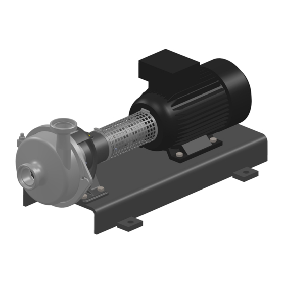
Description Pump overview Description Pump overview Fig.1: HYGIA CN 0103 - Annular casing 0800 - Motor 0153 - Suction port 0840 - Coupling 0156 - Discharge port 0890 - Base plate 0331 - Bearing housing Description The pump is a end suction, single-stage centrifugal pump in system block design. All wetted parts are based on the “hygienic design”... -
Page 18: Hygienic Design Applications
Number of Pump name Size Design type width poles [kW] Type plate GEA Hilge Niederlassung der GEA Tuchenhagen GmbH Hilgestrasse - D - 55294 Bodenheim Pump-Type: Ser.-No.: TAG No.: YOM: Made in Germany Fig.2: Type plate GEA Hilge Pump type: Pump name P: Motor rating Serial No.: Serial number... -
Page 19: Transport And Storage
Transport and Storage Special personnel qualification for transport and storage Transport and Storage Special personnel qualification for transport and storage Transports may only be carried out by qualified staff, who must observe the safety instructions. Safety precautions for transport and storage Warning! Falling loads Danger from falling loads. -
Page 20: Dimensions / Weights
Transport and Storage Dimensions / weights Dimensions / weights Design: Pump on steel base plate with DKM coupling Weights [kg] GEA Hilge HYGIA I CN IEC size Weight [kW] [min-1] [kg] 0.55 1450 55.5 0.75 1450 56.5 2900 1450 60.5 2900 62.5... -
Page 21: Disposal Of Packaging Material
Transport and Storage Disposal of packaging material Should you nevertheless find any damage after cautious unpacking and exact inspection of the shipment, immediately notify the carrier (railway, post, freight forwarder, shipping company). Make claims for damages. The transport risk passes to the customer once the shipment has left our warehouse. Disposal of packaging material The generation of waste should be avoided or minimized wherever possible. -
Page 22: Technical Data
Technical data Serial number Technical data The operating safety of the delivered machine is only guaranteed if the machine is used as intended according to the sections of the operating instructions and the purchase order. Warning! Overload of the pump! ►... -
Page 23: Maximum Operating Temperatures
Technical data Maximum operating temperatures Maximum operating temperatures Warning! Exceeding the maximum temperatures! ► Never exceed the specified operating temperatures. Operating temperatures Version Temp. [°C] Normal version Sterilisation (SIP) Variations are possible at the above temperatures. Maximum operating pressure Warning! Pressure overload of the pump! ►... - Page 24 Technical data Sealing resistance table Gasket material Medium Temperature (general operating temperature) EPDM -40...+135°C -10...+200 °C (-40...275°F) (+14...+392°F) Inorganic acids up to 5% up to 80 °C (176°F) Inorganic acids up to 5% up to 100 °C (212°F) – Water up to 80 °C (176°F) Steam up to 135 °C (275°F)
-
Page 25: Assembly And Installation
Assembly and installation Safety precautions for setup, installation, and connection Assembly and installation Safety precautions for setup, installation, and connection Warning! Tipping (tilting) of the pump! ► The surface for setting up the pump should be clean, level and have sufficient load-bearing capacity. - Page 26 Assembly and installation Safety precautions for setup, installation, and connection Warning! Overheating! ► Ensure adequate ventilation. ► Avoid sucking in the heated exhaust air also of adjacent units. ► Maintain minimum distances. Caution! Vibration! ► Ensure stable construction for mounting of the pump and piping. Insufficiently stiffened substructures may cause an overall structure capable of oscillating, which is excited to oscillate by hydraulic and/or motor forces during changing operating conditions in the system.
-
Page 27: Mechanical Seals In Tandem Arrangement
Assembly and installation Special personnel qualification 6.1.1 Mechanical seals in tandem arrangement Caution! Missing supply of flushing fluid! Dry running of the mechanical seal. ► Always connect the flushing lines such that supply for flushing is always ensured. ► Ensure that flushing fluid is supplied even when checking the motor’s direction of rotation. -
Page 28: Checking Smooth Running Of The Impeller
Assembly and installation Setup, installation, and connection 6.3.1 Checking smooth running of the impeller Before installation, check that the impeller is running smoothly. Perform the following steps: Remove the motor shroud (only for SUPER version). Remove the motor fan cover. Note the pump’s direction of rotation (arrow). - Page 29 Assembly and installation Setup, installation, and connection Fig.4: Relocation types (principle) A - axial offset B | angle offset C | radial offset To align the coupling carry out the following steps: Disassemble the coupling protection. Place a straightedge at four opposite points (in steps of 90° degrees) across both clutch halves.
-
Page 30: Permissible Displacement Values For Flender Couplings
Assembly and installation Setup, installation, and connection 6.3.3.1 Permissible displacement values for Flender couplings Permissible displacement values for Flender B / BDS coupling Axial offset type B Outer diameter of the coupling (da) Size of type B max. axial displacement [mm] (clearance) Axial offset type BDS Outer diameter of the coupling... - Page 31 Assembly and installation Setup, installation, and connection Permissible shaft offset values for radial offset ∆ Kr and difference of clearance (angle displacement) ∆ S2 [mm] Size of type H Size of type HDS 0.35 0.35 0.55 0.55 0.25 0.25 0.35 0.45 1 000 0.25...
-
Page 32: Permissible Displacement Values For Ktr Rotex, Dkm
Assembly and installation Setup, installation, and connection Torques and clearances for type H / HDS Size of type H Threaded pin DIN EN ISO 4029 (serrated cup point) Torque [Nm] Tighten the threaded pins (0904.00 / 0904.01) with the torques stated in the table. -
Page 33: Installation In The Piping System
Assembly and installation Setup, installation, and connection Permitted displacement values for Rotex DKM coupling Outer diameter of the coupling (da) max. angle displacement ∆ Kw [degree] at n=1500 1.00 1.00 1.00 1.00 1.00 1.00 1.00 1.00 1.00 1.00 max. angle displacement ∆... -
Page 34: Space Requirements
Assembly and installation Setup, installation, and connection 6.3.4.1 Space requirements Maintain the following minimum distances. Pay attention to motor performance. Horizontal assembly 0.5 5 - 4 k W 300 mm >5,5 kW 300 mm Fig.8: Space requirements 6.3.4.2 Noise and vibration damping To achieve optimum performance and to minimize noise and vibration, it is recommended to provide the pump with vibration dampers. - Page 35 Assembly and installation Setup, installation, and connection The correct damper depends on the respective installation. An incorrectly designed damper may even increase the vibration. Vibration dampers should therefore be designed by the vendor of the vibration damper. Compensators If the pump is mounted on a foundation along with vibration dampers, be sure to install compensators at the pipe connections.
-
Page 36: Using The Mechanical Seal
Assembly and installation Setup, installation, and connection Acoustic decoupling Fig.9: Example for the foundation of a pump A - compensators | B - solid base | C - Vibration damper 6.3.5 Using the mechanical seal For perfect operation, mechanical seals require a lubrication film in the sealing gap, which prevents contact between the two sliding surfaces. -
Page 37: Flushing Fluid (Optional)
Assembly and installation Setup, installation, and connection 6.3.6.1 Flushing fluid (optional) Requirements of the flushing fluid The flushing fluid has the task to lubricate and cool the product-side mechanical seal and the radial packing ring on the atmospheric side. The flushing fluid must meet the following criteria: •... - Page 38 Assembly and installation Setup, installation, and connection Connect the inlet line (A). Note position of the lines depending on the direction of rotation. Connect the outlet line (B). Check correct fit of the connections. → The flushing has been connected. Double mechanical seal - back-to-back arrangement (optional) Sealing fluid To maintain their function, mechanical seals need a sealing fluid, which has the...
-
Page 39: Defective Shaft Seal
Assembly and installation Setup, installation, and connection • Lubrication and cooling of the mechanical seals A clean liquid, compatible with the pumped fluid, is used as the flushing medium. Ensuring the flushing operation Open the inlet of flushing fluid. Vent the seal cartridge. Ensure pressureless circulation. -
Page 40: Delta Connection
Assembly and installation Setup, installation, and connection 6.3.7.2 Delta connection Delta connection for low voltage. Connect the pump according to the ordering information. The following figure shows the wiring diagram of the delta connection. Fig.13: Delta connection 6.3.7.3 Frequency converter operation All three-phase motors can be connected to a frequency converter. -
Page 41: Earthing
Assembly and installation Re-install all safety devices. With double mechanical seal in back-to-back arrangement, connect the sealing fluid (see Section 6.3.6, Page 36). Check that hydraulic connections are firmly secured. Open stop valves. With double mechanical seal in tandem arrangement, connect the flushing fluid (see Section 6.3.6, Page 36) Fill the pump (system). -
Page 42: Commissioning
Commissioning Special personnel qualification Commissioning Special personnel qualification The commissioning personnel must be suitably qualified for this work. See also Section 2.6, Page 15. Safety instructions for commissioning Caution! Hazard due to overheating and pressure overload! ► Never pump for longer than 30 seconds against a closed shut-off device. Pumping against a closed shut-off device leads to rapid warming of the pumped fluid and pressure increase. -
Page 43: Functional Testing Of The Mechanical Seal
Commissioning Fully open the suction-side stop valve. Close the pressure side stop valve. Switch on the pump. Slowly open the pressure side stop valve. → This completes the commissioning. If there is no increase of delivery head after commissioning: Switch off the pump. Again vent the pump (system). -
Page 44: Cleaning
Cleaning Special personnel qualification Cleaning To ensure the quality of sensitive fluids, pumps must be cleaned immediately after each use. Only in this way will adhesions and deposits be removed completely and contamination of the products be prevented. To achieve the best possible results, Hilge pumps are optimised with regard to gap and dead spaces, designed according to DIN EN 13951, and resistant to the cleaning agents referred to in the following chapter. -
Page 45: Cip
Cleaning Warning! Pressure shock by evaporating liquid! ► Completely empty the system before steam sterilisation. Notice Disposal of cleaning agents ► Dispose of cleaning agents properly and in an environmentally friendly way. CIP stands for Cleaning in Place, the pump is completely rinsed with cleaning agents. -
Page 46: Sip
Cleaning Cleaning agents that contain hydrochloric acid (HCl) or hydrofluoric acid (HF) must not be used. Consult the supplier for the use of special cleaning agents and procedures with respect to the materials. Thoroughly rinse the pump with water to remove any cleaning agents leaving no residues. -
Page 47: Maintenance / Servicing
Pump maintenance 9.3.1 Inspektionen Die Pumpe ist weitgehend wartungsfrei. Um eventuellen Störungen vorzubeugen, empfiehlt GEA, regelmäßig Sichtprüfungen (Inspektionen) durchzuführen. Dabei sollte besonderes Augenmerk auf die Dichtheit und die korrekte Funktion der Pumpe gelegt werden. Um höchste Betriebssicherheit der Pumpe zu gewährleisten, sollten spätestens nach 2000 Betriebsstunden Verschleißteile, wie Gleitringdichtung und O-Ringe,... -
Page 48: Replacement Of O-Rings
Maintenance / servicing Maintenance of the CN bearing 9.3.1.1 Replacement of O-rings Notice Hygiene risk, food safety Worn out and not fully functional components may lead to the contamination of the pump. ► Pay close attention to the condition of the O-rings during regular inspections. -
Page 49: Bearing Replacement
Maintenance / servicing Maintenance of the CN bearing are installed as fixed bearings in an X-arrangement to accommodate axial and radial forces from all directions. On the pump-side there is only a single-row cylindrical roller bearing that absorbs only radial bearing forces. It allows for axial displacements in both directions. 9.4.2 Bearing replacement Replace the bearings after approx. -
Page 50: Roller Bearing Greases
Maintenance / servicing Roller bearing greases Roller bearing greases For the lubrication of roller bearings, use the listed roller bearing greases or established equivalents. Roller bearing greases Storage temperature <70 °C Storage temperature > 70 °C / < 100 °C Delivery fluid -10…95 °C Delivery fluid 96 °C...190 °C Factory-filled grease... -
Page 51: Maintenance Of The Motor
Maintenance / servicing Maintenance of the motor Maintenance of the motor Motors without grease nipple Motors without grease nipple are equipped with lifetime lubrication. The grease life then depends on the bearing life. Prerequisite is that the motor must be used according to the specifications in the catalogue. -
Page 52: Malfunctions / Repairs
Malfunctions / repairs Special personnel qualification Malfunctions / repairs 10.1 Special personnel qualification The troubleshooting / repair personnel must be suitably qualified for this work. See also Section 2.6, Page 15. 10.2 Safety instructions Warning! Improper execution of work! ► Repair work should be carried out by authorised and qualified personnel. Danger Electric shock by touching live parts! ►... -
Page 53: Malfunctions And Remedies
Malfunctions / repairs Malfunctions and remedies Caution! Unsuitable tools! ► Make sure that all the parts can be mounted without damage. ► Use GEA Hilge assembly tools. 10.3 Malfunctions and remedies Actions for troubleshooting Malfunction Cause Remedy Pump does not Incorrect electrical connection (2 phases). -
Page 54: Repair
Malfunctions / repairs Repair Actions for troubleshooting Malfunction Cause Remedy Leakage at the Pump is strained (causing leaks at the pump body Install pump without strain, support piping by fixed pump body, or at the connections). points. connections, mechanical seal, Housing seals and connection seals defective. - Page 55 Malfunctions / repairs Repair If, despite careful emptying and cleaning of the pump, safety precautions are required, the necessary information must be given. 430BAL013363GB_1 27.02.2019...
-
Page 56: Gea Hilge Assembly Tool Kit
Malfunctions / repairs Repair 10.4.2 GEA Hilge assembly tool kit Tools from the GEA Hilge assembly tool kit prevent damage to the mechanical seal during assembly. Fig.15: GEA Hilge assembly tool kit 10.4.2.1 Contents and use Tools in the GEA Hilge assembly tool kit... -
Page 57: Parts Overview
Malfunctions / repairs Repair 10.4.3 Parts overview 0161.00 0901.07 0412.00 0412.04 0927.00 0230.00 0934.03 0930.00 0902.02 0433.00 0922.00 0557.00 0934.00 0920.00 0412.05 0920.04 0554.00 0940.00 0501.00 0211.00 0103.00 0412.04 0230.00 0930.00 0922.00 0433.00 0557.00 0412.05 0103.00 0161.00 0412.00 0501.01 0905.00 Fig.16: Parts overview –... -
Page 58: Parts Overview Cn Bearing Support
Malfunctions / repairs Repair 10.4.4 Parts overview CN bearing support Fig.17: Parts overview * Safety guard required only for single mechanical seal. Parts list CN bearing support Pcs. Item no. Designation Pcs. Item no. Designation 0211.00 Shaft 0636.01 Grease nipple Angular contact ball 0326.00 0686.00... -
Page 59: Parts Overview Of Coupling And Motor
Malfunctions / repairs Repair Parts list CN bearing support 0507.04 Deflector 0970.01 Rotation arrow 0636.00 Grease nipple 10.4.5 Parts overview of coupling and motor 0940.02 0940.01 0800.00 0211.00 0904.01 0867.01 0840.01 0869.00 0904.00 0867.00 0840.00 Fig.18: Parts overview Parts list for the coupling and motor Pcs. -
Page 60: Installing Cn Bearing Support Size 1 And 2
Malfunctions / repairs Repair 10.4.7 Installing CN bearing support size 1 and 2 Install the CN bearing support as follows: 0733.02 Fig.19: CN bearing support Push the angular contact ball bearing (0326.00) onto the shaft (0211.00). Push the supporting disk (0504.00) onto the shaft (0211.00) until it lightly touches the angular contact ball bearing (0326.00). -
Page 61: Install Coupling
Malfunctions / repairs Repair Optional: Push the cover hood (0517.01) onto the bearing block (0331.00). 10.4.8 Install coupling Install coupling Push the coupling half (0840.00) onto the shaft (0211.00). Insert the threaded pin (0904.00) one to two rotations into the clutch half (0840.00). Fig.20: Clutch half, pump shaft Push the clutch half (0840.01) onto the motor... - Page 62 Malfunctions / repairs Repair Install coupling Align the coupling with a straightedge. Observe the permissible displacement values in chapter Align the coupling. Fig.24: Coupling, straightedge Tighten the screws for motor (0800.00), coupling (0840.00/01) and bearing support (0330.00). Check again the correct alignment of the coupling and correct if if necessary.
-
Page 63: Installing Single Mechanical Seal
Malfunctions / repairs Repair 10.4.9 Installing single mechanical seal Equipment and tools from the GEA Hilge assembly tool kit • Loctite Type 243 • Klüber paste UH1 96-402 Connecting the back plate with the bearing housing Wet the threads of the stud bolts (0902.00) with Loctite Type 243 and screw them by hand (!) into the back plate (0161.00). -
Page 64: Determining Gap Size On Hygia
Malfunctions / repairs Repair 10.4.10 Determining gap size on HYGIA Fig.30: Gap size on HYGIA General The gap size needs to be determined only if modifying/replacing the impeller or the ring housing. The gap between the impeller and the annular casing contributes crucially to complying with the intended use. - Page 65 Malfunctions / repairs Repair Carefully place the annular casing (0103.00) against the back plate (0161.00). Thus, the impeller (0230.00) is pushed by the annular casing (0103.00) into the zero gap position. The air gap then forms behind the impeller. Remove annular casing (0103.00) so that the impeller (0230.00) does not move, retaining its position.
-
Page 66: Installing Single Conical Spring Mechanical Seal
Malfunctions / repairs Repair 10.4.11 Installing single conical spring mechanical seal Equipment and tools from the GEA Hilge assembly tool kit • Spray bottle • Plastic mounting sleeve • Mounting sleeve Installing single conical spring mechanical seal Wet the fixed ring (counter ring) of the mechanical seal (0433.00) and the shaft (0211.00) with clean... - Page 67 Malfunctions / repairs Repair Installing single conical spring mechanical seal Push the rotating unit of the mechanical seal (0433.00) in the assembled state onto the shaft (0211.00) as far as it will go. Fig.34: Mechanical seal Push the seal spacer (0557.00) onto the shaft. Fig.35: Seal spacer →...
-
Page 68: Installing The Single Mechanical Seal - Spring Encapsulated (Hygiene)
– Easy to clean – For adhesive media – Optimal arrangement in the pump chamber Equipment and tools from the GEA Hilge assembly tool kit: • Spray bottle • Plastic mounting sleeve Prior to installation Check the shaft and counter ring holder for impurities and damage (sharp edges). - Page 69 Malfunctions / repairs Repair Check all O-rings of the mechanical seal for correct seating, and adjust if necessary. Moisten all sliding O-rings with water. → Done. Assembly Slide the fixed ring (counter ring) of the mechanical seal (0433.00) along with the O-ring over the shaft into the seat.
-
Page 70: Installing Double Mechanical Seal
Repair 10.4.13 Installing double mechanical seal Hint! This section applies to the installation of the double mechanical seal in back-to-back and tandem arrangements Equipment and tools from the GEA Hilge assembly tool kit • Spray bottle • Plastic mounting sleeve •... - Page 71 Connect the seal cartridge (0491.00) with the back plate (0161.00) GEA Hilge HYGIA I: Fastening from the front with Phillips screws (1000.03) Torque: M4: 1.5 - 2 Nm GEA Hilge HYGIA II: Fastening from the rear with hex socket screws (0914.02), washer (0554.03).
- Page 72 Connecting the seal cartridge GEA Hilge HYGIA I / II The seal cartridge is required for the double mechanical seal. Its mounting is very similar for the GEA Hilge HYGIA I and GEA Hilge HYGIA II. Fig.44: Connection of seal cartridge...
- Page 73 Malfunctions / repairs Repair Installing double mechanical seal Wet the fixed ring (stationary ring) of the mechanical seal (0433.01) and the shaft (0211.00) with clean water. Fig.47: Stationary ring of the mechanical seal Push the fixed ring (stationary ring) of the mechanical seal (0433.01) with the mounting sleeve into the seat of the seal cartridge (0491.00).
- Page 74 Malfunctions / repairs Repair Installing double mechanical seal Push the rotating unit (rotary ring) of the mechanical seal (0433.01) into the shaft (0211.00) as far as it will go in the assembled state with the mounting sleeve. Fig.50: Rotary ring of the mechanical seal Remove the mounting sleeve.
-
Page 75: Installing Tandem Double Mechanical Seal
Malfunctions / repairs Repair 10.4.14 Installing tandem double mechanical seal Equipment and tools from the GEA Hilge assembly tool kit • Spray bottle • Plastic mounting sleeve • Mounting sleeve • Loctite Type 243 • Klüber paste UH1 96-402 •... - Page 76 Malfunctions / repairs Repair Installing tandem double mechanical seal Wet the O-ring (0412.03) with water and insert it into the sterile screws (0918.00). Fig.55: Sterile screw Insert the O-ring (0412.01) into the seal cover (0471.00). Fig.56: Seal cover Use the sterile screws (0918.00) to fasten the seal cover (0471.00) to the back plate (0161.00).
-
Page 77: Installing Double Mechanical Seal In Back-To-Back Position
Malfunctions / repairs Repair 10.4.15 Installing double mechanical seal in back-to-back position Installing double mechanical seal in back-to-back position Hint! Start by following the steps in Section 10.4.14, Page 75. Push the adjusting ring (0516.00) onto the shaft (0211.00). Wet the mounting sleeve with clean water and push it onto the shaft shoulder. - Page 78 Malfunctions / repairs Repair Installing double mechanical seal in back-to-back position Wet the O-ring (0412.03) with water and insert it into the sterile screws (0918.00). Fig.61: Sterile screw Use the sterile screws (0918.00) to fasten the seal cover (0471.00) to the back plate (0161.00). torque: M6: 8 Nm Use the socket wrench with plastic insert to tighten the sterile screws.
-
Page 79: Installing Impeller And Housing
Malfunctions / repairs Repair 10.4.16 Installing impeller and housing Equipment and tools from the GEA Hilge assembly tool kit: • Klüber paste UH1 96-402 • Extractor • Spray bottle • Socket wrench • Socket wrench bit Install impeller Insert the feather key (0940.00). - Page 80 Klüber paste. Fig.67: Impeller nut Grease lock washer (0930.00) with Klüber paste. Hint! Only use original part lock washers from GEA Hilge for securing the impeller mounting. Fig.68: Lock washers Grease lock washers as shown. • (0230.00) Impeller | (0412.04) O-ring 0922.00...
- Page 81 Malfunctions / repairs Repair Install impeller Replace lock washers (0930.00) after 5-time use. Fig.70: Lock washer Insert the lock washers (0930.00) into the impeller nut (0922.00). Fig.71: Lock washers in impeller Unscrew impeller nut (0922.00) by hand. Leave a gap of about 3 mm for the O-ring (0412.04). Fig.72: Impeller nut Wet the O-ring (0412.04) with water and use the...
- Page 82 Malfunctions / repairs Repair Install impeller To prevent damage, use socket wrench with bit to tighten the impeller nut (0922.00). Notice Hygiene risk, food safety Damaged and scratched surfaces can cause contamination. ► Always tighten impeller nut with socket Fig.74: Socket wrench with insert wrench and insert.
- Page 83 Malfunctions / repairs Repair Installing the KLM housing Wet the O-ring (0412.00) with water and insert it into the back plate (0161.00). Fig.77: Back plate, O-ring Install the annular casing (0103.00). Fig.78: Annular casing Grease the thread of the connecting screw (0905.00) with Klüber paste.
- Page 84 Malfunctions / repairs Installing the KLM housing Align the annular casing (0103.00) via the pressure piece using a mechanic’s spirit level. Fig.80: Annular casing Tighten the hex nut (0920.00). Torque M10: 35 Nm Use a plastic mallet to bring the clamp ring into the correct position.
-
Page 85: Decommissioning
→ The pump has been temporarily decommissioned. 11.4 Disposal Discard the pump or parts thereof in an environment-friendly manner: Use the service of public or private disposal companies. If this is not possible, contact the next GEA Hilge company or service centre. 430BAL013363GB_1 27.02.2019... - Page 86 Appendix Appendix 430BAL013363GB_1 27.02.2019...
- Page 87 Appendix Certificate of non-objection 12.1 Certificate of non-objection 430BAL013363GB_1 27.02.2019...
- Page 88 Appendix Certificate of non-objection This section contains a certificate of non-objection. In the event of inspection or repair send the pump including this certificate to HILGE. Certificate of non-objection The following pump and its accessories, together with this certificate of non-objection, are herewith contracted out by the undersigned for inspection/repair: Pump data •...
- Page 89 Appendix 430BAL013363GB_1 27.02.2019...
- Page 90 • GEA is a global technology company with multi-billion euro sales operations in more than 50 countries. Founded in 1881 the company is one of the largest providers of innovative equipment and process technology. GEA is listed in the STOXX ®...
Need help?
Do you have a question about the Hilge HYGIA CN and is the answer not in the manual?
Questions and answers