GEA Hilge HYGIA K Operating Manual
Hide thumbs
Also See for Hilge HYGIA K:
- Operating instruction (78 pages) ,
- Operating instructions manual (94 pages)

Related Manuals for GEA Hilge HYGIA K


Summary of Contents for GEA Hilge HYGIA K
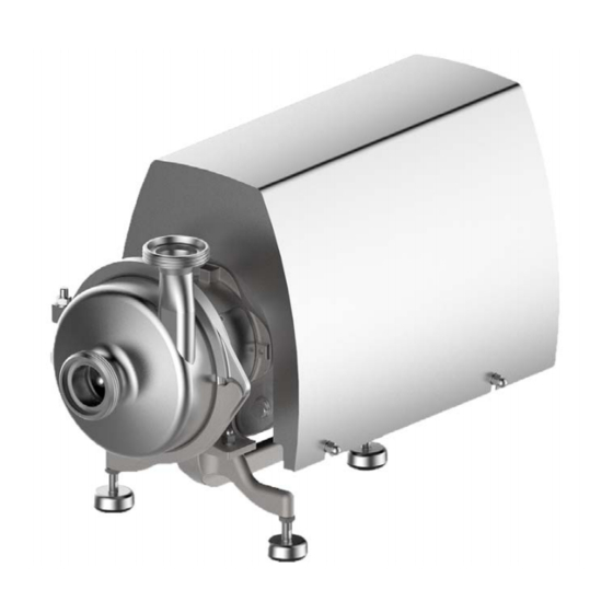
- Page 1 GEA Hilge HYGIA K Operating manual (Translation of the original operating manual) BA.H2A.KYY.001.01.17.GB gea.com...
- Page 2 Annex VII, Part B and we obligate to provide these upon reasoned request from the individual national authorities by data transfer. HILGE GmbH & Co.KG Authorized person for compiling and handing over Hilgestraße 37-47 technical documentation: 55294 Bodenheim, Germany Bodenheim, Tatiana Gillitzer Managing Director GEA Hilge...
-
Page 3: Table Of Contents
Operating manual GEA Hilge HYGIA K 1 Introduction _________________________________________________________________________________________ 5 1.1 Target group ________________________________________________________________________________ 5 1.2 Symbols and formatting ________________________________________________________________________ 5 1.3 References to the document ____________________________________________________________________ 5 2 Safety _____________________________________________________________________________________________ 5 2.1 Operator notes ______________________________________________________________________________ 5 2.1.1 Unpacking the pump __________________________________________________________________ 5 2.1.2 Storing the pump _____________________________________________________________________ 5... - Page 4 Operating manual GEA Hilge HYGIA K 6.4.2 Overview of parts of the K Lantern ______________________________________________________ 21 6.4.3 Overview of the drive parts ____________________________________________________________ 22 6.4.4 Instructions for disassembly ___________________________________________________________ 22 6.4.5 Instructions for assembly ______________________________________________________________ 23 6.4.6 Mounting of the shaft sleeve ___________________________________________________________ 23 6.4.7 Assembly of the motor, lantern and pump shaft ____________________________________________ 24...
-
Page 5: Introduction
Operating manual Introduction GEA Hilge HYGIA K Introduction Safety Overview Overview This section describes the requirements that are important for This section describes what you have to consider for your own reading and understanding this operating manual. The symbols safety. Read this important section attentively and follow the and formats that make the reading easier are also described. -
Page 6: Identification Of Instructions In The Operating Manual
Safety Operating manual GEA Hilge HYGIA K Identification of instructions in the operating Qualification and training of personnel manual The employees operating, maintaining, inspecting, and installing the pump must have the appropriate qualifications for this work. The operator must define in detail the tasks for which the 2.3.1... -
Page 7: Unauthorised Modifications And Spare Parts
Operating manual Safety GEA Hilge HYGIA K WARNING! Tripping hazard from electric power cable! ▲ Death, serious bodily injury. ► Route the electric power cable in such a way that no one can trip over it (in case of porta- ble pumps). -
Page 8: Cip
Safety Operating manual GEA Hilge HYGIA K 2.11.1 WARNING! Hot surfaces! CIP means Cleaning In Place. The pump is completely flushed ▲ Death, serious bodily injury, damage to prop- through with a detergent. The detergent used must be suitable for erty the cleaning task in question. -
Page 9: Repair Contract
Operating manual Product description GEA Hilge HYGIA K Product description 2.12 Repair contract The duty to follow the legal regulations on work safety and the regulations on environmental protection means that all Overview commercial enterprises must protect their employees, the public... -
Page 10: Proper Usage
Product description Operating manual GEA Hilge HYGIA K Hygienic design 3.3.4 Motor operation Because of the consistent hygienic design and the use of Do not start and stop the motor more than 15 times per hour. materials that are free of both pores and inclusions, the pump is highly suitable for use in: –... -
Page 11: Nameplate
Operating manual Product description GEA Hilge HYGIA K 3.4.3 Nameplate HILGE GmbH & Co. KG Hilgestraße - D - 55294 Bodenheim Pump Type: Ser.-No.: TAG No.: YOM: Made in Germany Fig. 3: HILGE nameplate 1 - pump type 2 - pump serial number... -
Page 12: Weights
Product description Operating manual GEA Hilge HYGIA K 3.4.6 Weights Please note that, depending on design and accessories, the weights may differ from those indicated. If presented with the pump/order number, the manufacturer can give you precise information. GEA Hilge HYGIA I K... -
Page 13: Maximum Operating Temperature
Operating manual Mounting, installation and connection GEA Hilge HYGIA K Mounting, installation and connection 3.4.7 Maximum operating temperature WARNING! Exceeding the max. permissible operating tem- Overview perature! This section describes how to mount, install and connect the ▲ Death, serious bodily injury, damage to prop- pump. -
Page 14: Permissible Mountings
4.2.1 Permissible mountings CAUTION! Dry running! The GEA Hilge HYGIA K is designed for horizontal operation and ▲ Damage to property. may only be used in this orientation. ► The suction line must be absolutely leakproof and laid in such a way that no air pockets can form. -
Page 15: Space Requirements
Operating manual Mounting, installation and connection GEA Hilge HYGIA K Dry running To achieve a proper sealing, mechanical seals require a lubricating film between the sliding surfaces. Dry running occurs if the lubricant film between the sliding surfaces is missing or wears away. The frictional heat generated by direct contact of the sliding surfaces will damage the mechanical seal. -
Page 16: Connections For Flushing System
Mounting, installation and connection Operating manual GEA Hilge HYGIA K 4.4.2 Quench design CAUTION! Vibration! HILGE pumps with a quench are equipped with a lip seal. ▲ Damage to property. The unpressurised flushing liquid flows between the mechanical ► Make sure that pipes and pumps are fixed seal and this lip seal. -
Page 17: Star Connection
Operating manual Mounting, installation and connection GEA Hilge HYGIA K mends the use of insulated motor bearings to avoid increased DANGER! wear of motor bearings by bearing currents. Motors with frequency converters (Tronic) - risk Please consider the following operating conditions if the pump is... -
Page 18: Start-Up / Shut-Down
Start-up / shut-down Operating manual GEA Hilge HYGIA K Start-up / shut-down 2. Replace the mechanical seal. Observe safety instructions in chapter 6.1 on page 18. Overview This section describes how to start up and shut down the pump. Shutting down the pump You get to know which inspections contribute to failure-free operation and increased life of the pump. -
Page 19: Maintenance Of The Pump
Operating manual Maintenance/servicing GEA Hilge HYGIA K Maintenance of the pump DANGER! For motors with frequency converters (Tronic) - The pump is a low-maintenance pump. In addition to cleaning, risk of electric shock from live parts! the only point to be kept in mind is the wear to the rotating ▲... -
Page 20: Assembly
Maintenance/servicing Operating manual GEA Hilge HYGIA K Assembly 6.4.1 Overview of parts 0161.00 0902.02 0901.07 0412.00 0412.04 0927.00 0230.00 0934.03 0930.00 0433.00 0922.00 0557.00 (*2) 0412.05 (*2) 0103.00 0920.00 0421.06 (*1) 0554.00 0932.09 (*1) 0501.00 0412.00 0902.02 0161.00 0412.04 0230.00 0901.32 (*1) -
Page 21: Overview Of Parts Of The K Lantern
Operating manual Maintenance/servicing GEA Hilge HYGIA K 6.4.2 Overview of parts of the K Lantern 0736.04 (*1) 0731.30 (*1) 0346.00 0970.00 0930.18 1000.11 0686.02 0914.05 0554.74 0901.50 0686.01 0920.04 0554.73 0340.00 0731.31 (*1) 0736.05 (*1) (*1) - for Quench version only Fig. -
Page 22: Overview Of The Drive Parts
Maintenance/servicing Operating manual GEA Hilge HYGIA K 6.4.3 Overview of the drive parts 0970.03 0970.01 0940. 0940.00 0901.49 0930.02 0515.05 0801. 0515.06 0920.09 0554.75 0211.00 (*) - optional Fig. 15: Overview of parts (**) - applies to motor shroud Part No. -
Page 23: Instructions For Assembly
Operating manual Maintenance/servicing GEA Hilge HYGIA K 6.4.5 Instructions for assembly – hammer, wire cutter, and, when necessary, filler and sand- paper. How to mount the shaft sleeve DANGER 1. Clean the surface of the pump shaft and remove any burrs. -
Page 24: Assembly Of The Motor, Lantern And Pump Shaft
Maintenance/servicing Operating manual GEA Hilge HYGIA K 6.4.7 Assembly of the motor, lantern and pump shaft ATTENTION Damage to motor shaft and bearings! ▲ Damage to property ► Do not place the pump vertically on the lid of the motor fan or assemble the pump in this position. - Page 25 Operating manual Maintenance/servicing GEA Hilge HYGIA K 8. Grease hexagon screws 0901.32 with Klüberpaste and con- 9. Moisten grub screws 0902.02 with Loctite 243 and screw nect seal cartridge 0491.00 to housing lid 0161.00. these up to the stop in Torque M6: 8 Nm housing lid 0161.00.
- Page 26 Maintenance/servicing Operating manual GEA Hilge HYGIA K 15.Push the assembly sleeve onto shaft 0211.00 to enable the 16.Screw on impeller nut 0922.00 without the O-ring and clamp connection to be positioned. tighten. The correct length of the shaft is now set.
-
Page 27: Assembly Of The Single Mechanical Seal, Spiral Spring
Operating manual Maintenance/servicing GEA Hilge HYGIA K 6.4.8 Assembly of the single mechanical seal, spiral spring 1. Spray the stationary ring of the mechanical seal 0433.00 2. Push the stationary ring of the mechanical seal 0433.00 into and the shaft 0211.00 with clean water. -
Page 28: Installing The Mechanical Seals
Maintenance/servicing Operating manual GEA Hilge HYGIA K 6.4.9 Installing the mechanical seals The following descriptions are brief guidelines on how to install different types of mechanical seals. The pump data sheet (order documentation) indicates the design of the mechanical seal integrated into your pump. -
Page 29: Assembly Of Impeller And Pump Housing
Operating manual Maintenance/servicing GEA Hilge HYGIA K 6.4.10 Assembly of impeller and pump housing 1. Insert key 0940.00. 2. Insert O-ring 0412.05 into seal spacer 0557.00 or mechani- cal seal 433.00. MF-928 MF-929 Fig. 40: Key Fig. 41: O-ring 3. Grease impeller seat and threaded shaft. - Page 30 Maintenance/servicing Operating manual GEA Hilge HYGIA K 7. Insert Nord-Lock washer 0930.00 into impeller nut 0922.00. 8. Tighten impeller nut 0922.00 by hand. Leave about a 3 mm space for the O-ring 0412.04. MF-934 Fig. 48: Nord-Lock washer in impeller nut MF-618 Fig.
- Page 31 Operating manual Maintenance/servicing GEA Hilge HYGIA K 15. Grease clamp screw 0905.00. Use Klüberpaste UH1 96- 17. Adjust pump housing 0103.00 via discharge branch using a 402 from the HILGE assembly tool kit. spirit level. 16.Assemble upper and lower clamping ring 0501.00 / 01 by hand-screwing clamp screw 0905.00, washer 0554.00 and...
-
Page 32: Assembly Of Super Shroud
Maintenance/servicing Operating manual GEA Hilge HYGIA K 6.4.11 Assembly of SUPER shroud Fig. 59: SUPER Shroud Piece Part No. Designation Piece Part No. Designation 0554.02 Washer 0901.02 Hexagon screw 0554.50 Washer 0904.20 Grub screw 0592.12 Support 0920.12 Hexagon nut 0592.13 Support 0920.81... -
Page 33: Troubleshooting
Operating manual Maintenance/servicing GEA Hilge HYGIA K Troubleshooting Problem Cause Remedy 1. Incorrect electrical connection (two phases). 1. Check the electrical connections and correct them if neces- sary. 2. Wrong direction of rotation. 2. Reverse the phases of the power supply (reverse the polar- 3. -
Page 34: Disposal
Fig. 60: HILGE assembly tool kit 6.7.1 Contents and use The list below specifies the tools of the kit: Item Definition of Items GEA Hilge HYGIA K I GEA Hilge HYGIA K II Assembly sleeve ∅ 19 ● Assembly sleeve ∅ 28 ●... -
Page 35: Certificate Of Non-Objection
Operating manual Certificate of non-objection GEA Hilge HYGIA K Certificate of non-objection • Delivery date: Reason for inspection / repair contract Overview This section contains a certificate of non-objection. In the event of inspection or repair send the pump including this certificate to HILGE. - Page 36 • • GEA Group is a global engineering company with multi-billion euro sales and operations in more than 50 countries. Founded in 1881, the company is one of the largest providers of innovative equipment and process technology. GEA Group is listed in the STOXX ®...
Need help?
Do you have a question about the Hilge HYGIA K and is the answer not in the manual?
Questions and answers