
Related Manuals for GEA Hilge HYGIA H ADAPTA


Summary of Contents for GEA Hilge HYGIA H ADAPTA
- Page 1 Hygienic Pumps GEA Hilge HYGIA H ADAPTA Operating instruction (Translation from the original language) BA.P2A.ADY.003.GB_1...
- Page 2 (print, photocopy, microfilm or another method) without the prior written permission of GEA Hilge Office of GEA Tuchenhagen GmbH hereinafter referred to as Manufacturer in any form (print, photocopy, microfilm or other process) reproduced or distributed. This restriction also applies to the drawings and diagrams included in the documentation.
- Page 3 These instructions were written to the best of our conscience. However, the manufacturer is not liable for any errors that may be contained in this document or for any resulting consequences. The manufacturer reserves the right to make technical changes by further development of the pump described in these instructions.
- Page 4 LAYOUT INFORMATION Bullet points and numbered list characters Bullet points are used to separate logical contents within a section: • Bullet point 1 Types of bullet point 1. • Bullet point 2 Types of bullet point 2. Numbered list characters are used to separate enumerations within a descriptive text: Descriptive text with consecutive numbering: –...
-
Page 5: Table Of Contents
TABLE OF CONTENTS General Information about this document Manufacturer address Customer Service EU Declaration of Conformity for Machines Safety Intended use 2.1.1 Pumped fluids 2.1.2 Minimum flow rate Minimum flow rates in explosive atmospheres 2.1.3 Connections and piping 2.1.4 Switching frequency 2.1.5 Types 2.1.6... - Page 6 10.3 Malfunctions and remedies 10.4 Repair 10.4.1 Repair order 10.4.2 GEA Hilge assembly tool kit Contents and use 10.4.3 Parts overview 10.4.4 Parts overview of ADAPTA bearing housing sizes 1 and 2 10.4.5 Parts overview ADAPTA bearing housing size 3 10.4.6...
-
Page 7: General
Versions, technical data and spare part numbers are subject to technical change. We reserve the right to implement changes due to technical progress. Manufacturer address GEA Hilge Niederlassung der GEA Tuchenhagen GmbH Hilgestraße 37-47 55294 Bodenheim Germany Phone +49 6135 7016-0 Fax +49 6135 1737 hilge@gea.com... -
Page 8: Eu Declaration Of Conformity For Machines
EU Declaration of Conformity for Machines in accordance with the EC Machinery Directive 2006/42/EC, Annex II 1. A Manufacturer: GEA HILGE Office of GEA Tuchenhagen GmbH Hilgestrasse 37-47 D 55294 Bodenheim Germany We declare under our sole responsibility that the machine... -
Page 9: Safety
Safety Intended use Safety Intended use Warning! Non-intended use! ► Pump only media that are specified in the order. The pump has been specially designed for them. ► Operate the pump only on the electrical grid that was specified in the purchase order. -
Page 10: Safety Precautions In These Operating Instructions
Safety Safety precautions in these operating instructions Safety precautions in these operating instructions Read the safety precautions! These operating instructions contain basic precautions that must be observed during installation, operation and maintenance. They must therefore be read by the installer and relevant personnel or operator prior to installation and commissioning. -
Page 11: Explanation Of The Safety Symbols Used
Safety Explanation of the safety symbols used Explanation of the safety symbols used Danger Stands for an immediate danger which leads to heavy physical injuries or to the death. ► Description to avert the danger Warning! Stands for a possibly dangerous situation which leads to heavy physical injuries or to the death. -
Page 12: Dangers Of Non-Compliance With Safety Information
Safety Unauthorised modification and ordering of spare parts Warning! Hazardous materials Contact with dangerous substances, e.g. by inhalation. ► Discharge the leakage of dangerous goods such that no danger to persons and the environment arises! ► Comply with legal provisions! ►... -
Page 13: Staff Qualifications And Training
Safety Staff qualifications and training Staff qualifications and training The staff for working on and with the pump must have the appropriate qualifications. Responsibilities, competencies and supervision of staff must be clearly defined by the operating company. If personnel do not have the necessary knowledge, they are to be trained and instructed. - Page 14 Safety – failure of the control circuit or control loop – incorrect assembly – fracture during operation – operating media or objects getting thrown out – loss of stability – personnel slipping, tripping or falling BA.P2A.ADY.003.GB_1 28.11.2018...
-
Page 15: Description
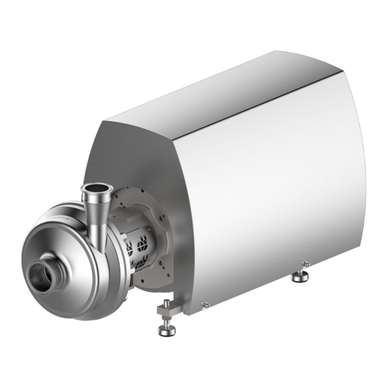
Description Pump overview Description Pump overview Fig.1: GEA Hilge HYGIA H ADAPTA 0130.00 - Annular casing 0330.00 - Bearing housing 0153.00 - Suction port 0680.00 - SUPER-cladding 0156.00 - Discharge port 0801.00 - Motor 0180.00 - Dome carrier Description The pump is a end suction, single-stage centrifugal pump in system block design. -
Page 16: Hygienic Design Applications
Number of Pump name Size Design type Nominal width [kW] poles Type plate GEA Hilge Niederlassung der GEA Tuchenhagen GmbH Hilgestrasse - D - 55294 Bodenheim Pump-Type: Ser.-No.: TAG No.: YOM: Made in Germany Fig.2: Type plate GEA Hilge Pump type: Pump name P: Motor rating Serial No.: Serial number... -
Page 17: Transport And Storage
Transport and Storage Special personnel qualification for transport and storage Transport and Storage Special personnel qualification for transport and storage Transports may only be carried out by qualified staff, who must observe the safety instructions. Safety precautions for transport and storage Warning! Falling loads Danger from falling loads. -
Page 18: Dimensions / Weights
Transport and Storage Dimensions / weights Dimensions / weights Weights [kg] HYGIA HI ADAPTA P2 [kW] Pole 100L 112M 132S Weights [kg] HYGIA HI ADAPTA P2 [kW] Pole 132S 132S 160M 160M 18.5 160L 180M 200L 200L 225M Unpacking the pump All of our pumps leave our warehouse properly packaged to avoid damage in transit. -
Page 19: Technical Data
Technical data Serial number Technical data The operating safety of the delivered machine is only guaranteed if the machine is used as intended according to the sections of the operating instructions and the purchase order. Warning! Overload of the pump! ►... -
Page 20: Maximum Operating Temperatures
Technical data Maximum operating temperatures Maximum operating temperatures Warning! Exceeding the maximum temperatures! ► Never exceed the specified operating temperatures. Operating temperatures Design Temp. [°C] Normal version Sterilisation (SIP) Maximum operating pressure Warning! Pressure overload of the pump! ► Operate the pump according to the ordering data. ►... -
Page 21: Assembly And Installation
Assembly and installation Safety precautions for setup, installation, and connection Assembly and installation Safety precautions for setup, installation, and connection Warning! Tipping (tilting) of the pump! ► The surface for setting up the pump should be clean, level and have sufficient load-bearing capacity. - Page 22 Assembly and installation Safety precautions for setup, installation, and connection Warning! Overheating! ► Ensure adequate ventilation. ► Avoid sucking in the heated exhaust air also of adjacent units. ► Maintain minimum distances. Caution! Vibration! ► Ensure stable construction for mounting of the pump and piping. Insufficiently stiffened substructures may cause an overall structure capable of oscillating, which is excited to oscillate by hydraulic and/or motor forces during changing operating conditions in the system.
-
Page 23: Special Personnel Qualification
Assembly and installation Special personnel qualification Caution! Voltage spikes in frequency converter operation! ► Use a motor suitable for frequency converter operation. ► Use a dU/dt filter to avoid voltage spikes or a motor with reinforced windings. Caution! Dry running of the mechanical seal when checking the direction of rotation. ►... -
Page 24: Installation In The Piping System
Assembly and installation Setup, installation, and connection Fig.4: Permissible setups of the pump Aligning the pump: Level the unit via the machined planar surfaces of the ports using a machine spirit level. After aligning the unit, tighten the fastening screws evenly in a crosswise sequence (where applicable). -
Page 25: Noise And Vibration Damping
Assembly and installation Setup, installation, and connection Horizontal installation 0.5 5 - 4 k W 300 mm < 5. 5 k W 300 mm Fig.6: Minimum distances in horizontal installation 6.3.3.2 Noise and vibration damping To achieve optimum performance and to minimize noise and vibration, it is recommended to provide the pump with vibration dampers. - Page 26 Assembly and installation Setup, installation, and connection To avoid the transmission of vibrations to the building, it is recommended to disconnect the pump foundation from parts of the building using vibration dampers. Selecting the correct vibration damper requires the following data: •...
-
Page 27: Using The Mechanical Seal
Assembly and installation Setup, installation, and connection 6.3.4 Using the mechanical seal For perfect operation, mechanical seals require a lubrication film in the sealing gap, which prevents contact between the two sliding surfaces. Usually this lubrication film is formed by the pumped product or by an externally supplied flushing/sealing fluid. -
Page 28: Double Mechanical Seals (Optional)
Assembly and installation Setup, installation, and connection • no chemical or mechanical attacking of the pump materials, sealing materials, and elastomers. • No contaminating of the pumped fluid • Viscosity < 5 mPas • Water hardness < 5° dH Demineralised water meets these requirements to a large extent. 6.3.5.2 Double mechanical seals (optional) Pumps with double-acting mechanical seals are equipped with a seal cartridge. -
Page 29: Electrical Connection
Assembly and installation Setup, installation, and connection • Protection against dry running • Lubrication and cooling of the mechanical seals A clean liquid, compatible with the pumped fluid, is used as the flushing medium. Ensuring the flushing operation Open the inlet of flushing fluid. Vent the seal cartridge. -
Page 30: Frequency Converter Operation
Assembly and installation Setup, installation, and connection Fig.11: Delta connection 6.3.6.3 Frequency converter operation All three-phase motors can be connected to a frequency converter. Frequency converter operation may subject the insulation of the motor to a higher load so that louder motor noise than in the normal case may occur due to eddy currents caused by voltage spikes. - Page 31 Assembly and installation Setup, installation, and connection With double mechanical seal in tandem arrangement, connect the flushing fluid (see Section 6.3.5, Page 27) Fill the pump (system). Note the direction-of-rotation arrow on the pump. Switch on the motor briefly (1-2 seconds). Compare the direction of rotation with the specified direction (arrow).
- Page 32 Assembly and installation Earthing the machine pad support Fig.13: Earthing connection dome carrier BA.P2A.ADY.003.GB_1 28.11.2018...
-
Page 33: Commissioning
Commissioning Special personnel qualification Commissioning Special personnel qualification The commissioning personnel must be suitably qualified for this work. See also Section 2.6, Page 13. Safety instructions for commissioning Caution! Hazard due to overheating and pressure overload! ► Never pump for longer than 30 seconds against a closed shut-off device. Pumping against a closed shut-off device leads to rapid warming of the pumped fluid and pressure increase. -
Page 34: Functional Testing Of The Mechanical Seal
Commissioning Slowly open the pressure side stop valve. → This completes the commissioning. If there is no increase of delivery head after commissioning: Switch off the pump. Again vent the pump (system). Repeat steps 6 to 9, and follow Section 10.3, Page 44. 7.3.3 Functional testing of the mechanical seal Perform the following steps:... -
Page 35: Cleaning
Cleaning Special personnel qualification Cleaning To ensure the quality of sensitive fluids, pumps must be cleaned immediately after each use. Only in this way will adhesions and deposits be removed completely and contamination of the products be prevented. To achieve the best possible results, Hilge pumps are optimised with regard to gap and dead spaces, designed according to DIN EN 13951, and resistant to the cleaning agents referred to in the following chapter. -
Page 36: Cip
Cleaning Warning! Pressure shock by evaporating liquid! ► Completely empty the system before steam sterilisation. Notice Disposal of cleaning agents ► Dispose of cleaning agents properly and in an environmentally friendly way. CIP stands for Cleaning in Place, the pump is completely rinsed with cleaning agents. -
Page 37: Sip
Cleaning SIP stands for sterilisation in place, in which the pump is sterilised with superheated steam. For steam sterilization or sanitization, minimum temperatures of 121 ° C (250 ° F) must be applied to all wetted surfaces. The maximum permissible temperatures can be obtained from the section technical data. -
Page 38: Maintenance / Servicing
Inspections The pump is maintenance-free for the most part. In order to prevent possible malfunctions, GEA recommends that regular visual inspections be carried out. Special attention should be paid to the leak tightness and the correct functioning of the pump. -
Page 39: Maintenance Intervals
Maintenance / servicing Maintenance of the ADAPTA bearing The O-rings must be replaced if any one of these characteristics are visible: – The O-ring is deformed at one or more locations. – The O-ring has cracks. – The surface of the O-ring is porous and brittle. –... -
Page 40: Bearing Housing Design Size 3
Maintenance / servicing Maintenance of the ADAPTA bearing Grease quantities for installation Volume [cm ] per bearing Quantity [g] per bearing 23.7 9.4.2 Bearing housing design size 3 The bearing consists of two angular contact ball bearings 0326.00 and one cylindrical roller bearing 0327.00. -
Page 41: Grease Filling
Maintenance / servicing Maintenance of the ADAPTA bearing • bearing temperature above 70 °C with standard grease (UNIREX N3) • bearing temperature above 100 °C up to 120 °C with hot bearing grease (OKS 4200) we recommend replacing the bearings after approximately 5,000 operating hours. 9.4.5 Grease filling In the factory, the cavities between the rolling elements are completely filled with... -
Page 42: Maintenance Of The Motor
Maintenance / servicing Maintenance of the motor Maintenance of the motor Motors without grease nipple Motors without grease nipple are equipped with lifetime lubrication. The grease life then depends on the bearing life. Prerequisite is that the motor must be used according to the specifications in the catalogue. -
Page 43: Malfunctions / Repairs
Malfunctions / repairs Special personnel qualification Malfunctions / repairs 10.1 Special personnel qualification The troubleshooting / repair personnel must be suitably qualified for this work. See also Section 2.6, Page 13. 10.2 Safety instructions Warning! Improper execution of work! ► Repair work should be carried out by authorised and qualified personnel. Danger Electric shock by touching live parts! ►... -
Page 44: Malfunctions And Remedies
Malfunctions / repairs Malfunctions and remedies Caution! Unsuitable tools! ► Make sure that all the parts can be mounted without damage. ► Use GEA Hilge assembly tools. 10.3 Malfunctions and remedies Actions for troubleshooting Malfunction Cause Remedy Pump does not Incorrect electrical connection (2 phases). -
Page 45: Repair
Malfunctions / repairs Repair Actions for troubleshooting Malfunction Cause Remedy Leakage at the Pump is strained (causing leaks at the pump body Install pump without strain, support piping by fixed pump body, or at the connections). points. connections, mechanical seal, Housing seals and connection seals defective. -
Page 46: Gea Hilge Assembly Tool Kit
Malfunctions / repairs Repair 10.4.2 GEA Hilge assembly tool kit Tools from the GEA Hilge assembly tool kit prevent damage to the mechanical seal during assembly. Fig.15: GEA Hilge assembly tool kit 10.4.2.1 Contents and use Tools in the GEA Hilge assembly tool kit... -
Page 47: Parts Overview
Malfunctions / repairs Repair 10.4.3 Parts overview Fig.16: Parts overview HYGIA H I/II Parts overview Parts list HYGIA H I Parts list HYGIA H II Pcs. Part no. Designation Pcs. Part no. Designation 0103.00 Annular casing 0103.00 Annular casing 0161.00 Back plate 0161.00 Back plate... -
Page 48: Parts Overview Of Adapta Bearing Housing Sizes 1 And 2
Malfunctions / repairs Repair Parts overview Parts list HYGIA H I Parts list HYGIA H II 0930.01 Toothed lock washer 0922.00 Impeller nut 0930.01 Toothed lock washer 10.4.4 Parts overview of ADAPTA bearing housing sizes 1 and 2 Fig.17: Bearing housing up to motor frame size 160 Parts list of ADAPTA bearing housing sizes 1 and 2 Pcs. -
Page 49: Parts Overview Adapta Bearing Housing Size 3
Malfunctions / repairs Repair 10.4.5 Parts overview ADAPTA bearing housing size 3 Fig.18: Parts overview bearing housing of motor frame size180 and larger Parts list ADAPTA bearing housing size 3 Pcs. Part no. Designation Pcs. Part no. Designation 0211.00 Pump shaft 0686.00 Safety guard 0326.00... -
Page 50: Parts Overview Of Coupling And Motor
Malfunctions / repairs Repair 10.4.6 Parts overview of coupling and motor Fig.19: Parts overview Parts list for the coupling and motor Pcs. Part no. Designation Pcs. Part no. Designation 0211.00 Shaft 0867.02 Coupling insert 0346.00 Intermediate motor stool 0902.06 Stud screw 0554.06 Washer 0904.00... -
Page 51: Installation Instructions
Malfunctions / repairs Repair 10.4.8 Installation instructions Notice Hygiene risk, food safety Incorrect installation of the pump can cause subsequent contamination and thus impair food safety. ► Always observe the following instructions: – Use tools from the HILGE assembly tool kit for installation. –... -
Page 52: Installing Adapta Bearing Housing Size 1 And
Malfunctions / repairs Repair 10.4.10 Installing ADAPTA bearing housing size 1 and 2 Installing ADAPTA bearing housing size 1 and 2 Push the roller bearings (0326.00) onto the shaft (0211.00). Fix the roller bearings (0236.00) with the locknut (0926.00). Torque: 120-140 Nm. Replace the locknut when replacing the bearings. - Page 53 Malfunctions / repairs Repair Installing ADAPTA bearing housing size 1 and 2 Fasten the bearing cover (0360.01), using the spring washers (0934.05) and hex head screws (0901.04). Torque: 8 Nm Fig.24: Bearing cover Push the V-ring (0507.05) with greased sealing lip onto the shaft (0211.00) so that the sealing lip contacts the bearing cover (0360.01).
- Page 54 Malfunctions / repairs Repair Installing ADAPTA bearing housing size 1 and 2 Push the coupling half (0840.00) onto the shaft (0211.00). Make sure that the coupling half (0840.00) is flush with the shaft (0211.00). Fig.28: Coupling half, bearing housing Fix the clutch half (0840.00) with the threaded pin (0904.00).
- Page 55 Malfunctions / repairs Repair Installing ADAPTA bearing housing size 1 and 2 Check the coupling pad (0867.02) for wear, and replace if necessary. Fig.32: Coupling pad Push the clutch half (0840.01) onto the motor shaft and secure it with the threaded pin (0904.01). Make sure that the coupling half (0840.01) is flush with the motor shaft.
- Page 56 Malfunctions / repairs Repair Installing ADAPTA bearing housing size 1 and 2 Align the coupling half (0840.01). Permissible axial offset: 2-4 mm. Fasten the clutch half (0840.01) with the threaded pin (0904.00). Torque: 4 Nm. Fig.36: Feeler gauge Slide the splash ring (0507.00) onto the shaft (0211.00).
-
Page 57: Installing Adapta Bearing Housing Bg
Malfunctions / repairs Repair 10.4.11 Installing ADAPTA bearing housing BG 3 Equipment and tools from the GEA Hilge assembly tool kit • Klüber paste UH1 96-402 Installing ADAPTA bearing housing size 3 Slide the outer race of the cylindrical roller bearing (0327.00) from the pump side into the bearing... - Page 58 Malfunctions / repairs Repair Installing ADAPTA bearing housing size 3 Push the shaft (0211.00) along with the angular contact ball bearings (0326.00) into the bearing housing (0330.00). Fig.42: Shaft Install the pump side spacer (0504.01) and retaining ring (0932.00). Fig.43: Bearing cover Clean the bearing cover (0360.01) on the motor side.
- Page 59 Malfunctions / repairs Repair Installing ADAPTA bearing housing size 3 Push the V-rings (0507.02) and (0507.05) with greased sealing lips from both sides onto the shaft (0211.00) so that the sealing lips contact the bearing caps (0360.00/01). Fig.46: V-rings Insert the key (0940.01) into the shaft (0211.00). Do not use a mallet! The bearings could be damaged.
- Page 60 Malfunctions / repairs Repair Installing ADAPTA bearing housing size 3 Screw in the set screw (0904.01). torque: M8 - 8 Nm. Fig.50: Set screw Grease the stud bolts (0902.06) with Klüber paste UH1 96-402. Fig.51: Stud bolts Screw the stud bolts (0902.06) into the bearing housing (0330.00).
- Page 61 Malfunctions / repairs Repair Installing ADAPTA bearing housing size 3 Insert the key (0940.02) into the motor shaft. Fig.54: Check the coupling pad (0867.02) for wear and replace if necessary. Fig.55: Coupling pad Push the coupling half (0840.01) onto the motor shaft and secure it with the set screw (0904.01).
- Page 62 Malfunctions / repairs Repair Installing ADAPTA bearing housing size 3 Connect the bearing housing (0330.00) and motor (0801.00) with the spring washers (0934.06) and hex nuts (0920.09). Fig.58: Bearing housing Align the coupling half (0840.01). Permissible axial offset of the coupling halves: 4 mm Fig.59: Axial offset Fasten the coupling half (0840.01) with the set...
-
Page 63: Installing Single Mechanical Seal
Malfunctions / repairs Repair 10.4.12 Installing single mechanical seal Equipment and tools from the GEA Hilge assembly tool kit • Loctite Type 243 • Klüber paste UH1 96-402 Connecting the back plate with the bearing housing Wet the threads of the stud bolts (0902.00) with Loctite Type 243 and screw them by hand (!) into the back plate (0161.00). -
Page 64: Determining The Gap Size
Malfunctions / repairs Repair 10.4.13 Determining the gap size Fig.64: Gap size HYGIA H General The gap size needs to be determined only if modifying/replacing the impeller or the ring housing. The gap between the impeller and the annular casing contributes crucially to complying with the intended use. - Page 65 Malfunctions / repairs Repair Remove annular casing (0103.00) so that the impeller (0230.00) does not move, retaining its position. Screw the impeller nut (0922.00) onto the shaft so that it just touches the impeller without moving it. Determine gap a’ between the shaft shoulder and the impeller (0230.00) using a feeler gauge or the like.
-
Page 66: Installing Single Mechanical Seal
– Easy to clean – For adhesive media – Optimal arrangement in the pump chamber Equipment and tools from the GEA Hilge assembly tool kit: • Spray bottle • Plastic mounting sleeve Prior to installation Check the shaft and counter ring holder for impurities and damage (sharp edges). - Page 67 Malfunctions / repairs Repair Check all O-rings of the mechanical seal for correct seating, and adjust if necessary. Moisten all sliding O-rings with water. → Done. Assembly Slide the stationary ring (counter ring) of the mechanical seal (0433.00) along with the O-ring over the shaft into the seat. On a version with anti-twist protection, the slot and pin positions must match.
-
Page 68: Installing The Single-Flushed Mechanical Seal
Malfunctions / repairs Repair 10.4.15 Installing the single-flushed mechanical seal Hint! This section applies to the installation of the single-flushed mechanical seal. Equipment and tools from the GEA Hilge assembly tool kit • Spray bottle • Plastic mounting sleeve •... - Page 69 Malfunctions / repairs Repair Installing the single-flushed mechanical seal Wet the threads of the stud bolts (0902.00) with Loctite Type 243 and screw them by hand (!) into the back plate (0161.00). Fig.69: Back plate with stud bolts Press the radial packing ring (0421.06) into the seal cartridge (0491.00).
- Page 70 Malfunctions / repairs Repair Installing the single-flushed mechanical seal Press the seal cartridge (0491.00) into the seat of back plate (0161.00). Fig.73: Back plate with seal cartridge Connect the seal cartridge (0491.00) with the back plate (0161.00) Torque: M6: 8 Nm Fig.74: Back plate Screw the threaded pins (0904.22) with one to two...
- Page 71 Malfunctions / repairs Repair Installing the single-flushed mechanical seal Slide the pre-assembled shaft protection sleeve (0524.01) onto the pump shaft (0211.00) up to the shaft shoulder. Fig.77: Shaft protection sleeve, shaft Tighten the pre-assembled threaded pins (0904.22) in the shaft protection sleeve (0524.01). Fig.78: Shaft protection sleeve, threaded pins...
- Page 72 Malfunctions / repairs Repair Hint! Further installation steps • The next steps for installing the product-side mechanical seal are identical to installing the single mechanical seal. Therefore, observe the steps in the section "Installing single mechanical seal". BA.P2A.ADY.003.GB_1 28.11.2018...
-
Page 73: Installing The Double Mechanical Seal Tandem
Malfunctions / repairs Repair 10.4.16 Installing the double mechanical seal tandem Equipment and tools from the GEA Hilge assembly tool kit • Spray bottle • Plastic mounting sleeve • Mounting sleeve • Loctite Type 243 • Klüber paste UH1 96-402 •... - Page 74 Malfunctions / repairs Repair Installing the double mechanical seal tandem Wet the threads of the stud bolts (0902.00) with Loctite Type 243 and screw them by hand (!) into the back plate (0161.00). Fig.82: Back plate Insert the O-ring (0412.02) into the seal cartridge (0491.00).
- Page 75 Malfunctions / repairs Repair Installing the double mechanical seal tandem Grease the seat of the component that borders on the back plate (0161.00) with Klüber paste UH1 96-402. Fig.86: Contact surface of back plate / structural part Connect the back plate (0161.00) to the structural part, Use the stud bolt (0902.02), the washers (0554.81) and the nuts (0920.04).
- Page 76 Malfunctions / repairs Repair Installing the double mechanical seal tandem Wet the mounting sleeve with clean water and push it onto the shaft shoulder. Fig.90: Mounting sleeve Push the rotating unit (rotary ring) of the mechanical seal (0433.01) into the shaft (0211.00) as far as it will go in the assembled state with the mounting sleeve.
- Page 77 Malfunctions / repairs Repair Installing the double mechanical seal tandem Push the adjusting ring (0516.00) to the correct position on the shaft, using a suitable measuring tool. Lock the adjusting ring (0516.00) with the threaded pins (0904.02). Adjustment dimensions: HYGIA H I: L=48.5 HYGIA H II: L=58.9 Fig.94: Position of the adjusting...
- Page 78 Malfunctions / repairs Repair Installing the double mechanical seal tandem Insert the O-ring (0412.01) into the seal cover (0471.00). Fig.97: Seal cover Use the sterile screws (0918.00) to fasten the seal cover (0471.00) to the back plate (0161.00). Torque: M6: 8 Nm Use the socket wrench with plastic insert to tighten the sterile screws.
-
Page 79: Installing The Impeller And Housing
Malfunctions / repairs Repair 10.4.17 Installing the impeller and housing Equipment and tools from the GEA Hilge assembly tool kit: • Klüber paste UH1 96-402 • Extractor • Spray bottle • Socket wrench • Socket wrench bit Install impeller Insert the key (0940.00). - Page 80 Malfunctions / repairs Repair Install impeller Grease the thread of the impeller nut (0922.00) with Klüber paste. Fig.102: Impeller nut Grease lock washer (0930.00) with Klüber paste. Hint! Only use original spare part lock washers from Hilge for securing the impeller mounting.
- Page 81 Malfunctions / repairs Repair Install impeller Insert the lock washers (0930.00) into the impeller nut (0922.00). Fig.106: Lock washers in impeller Unscrew impeller nut (0922.00) by hand. Leave a gap of approx. 3 mm (0.12 ") for the O-ring (0412.04). Fig.107: Impeller nut Wet the O-ring (0412.04) with water and use the impeller nut (0922.00) to push it into the gap...
- Page 82 Malfunctions / repairs Repair Install impeller To prevent damage, use socket wrench with bit to tighten the impeller nut (0922.00). Notice Hygiene risk, food safety Damaged and scratched surfaces can cause contamination. ► Always tighten impeller nut with socket Fig.109 wrench and insert.
- Page 83 Malfunctions / repairs Installing the HP housing Wet the O-ring (0412.00) with water and insert it into the back plate (0161.00). Fig.113: O-ring for housing cover Install the annular casing (0103.00). Fig.114: HP housing Secure the housing (0103.00) with the washers (0554.80) and the hexagon nuts (0920.67).
-
Page 84: Decommissioning
→ The pump has been temporarily decommissioned. 11.4 Disposal Discard the pump or parts thereof in an environment-friendly manner: Use the service of public or private disposal companies. If this is not possible, contact the next GEA Hilge company or service centre. BA.P2A.ADY.003.GB_1 28.11.2018... -
Page 85: Appendix
Appendix Appendix BA.P2A.ADY.003.GB_1 28.11.2018... -
Page 86: Certificate Of Non-Objection
Appendix Certificate of non-objection 12.1 Certificate of non-objection BA.P2A.ADY.003.GB_1 28.11.2018... - Page 87 Appendix Certificate of non-objection This section contains a certificate of non-objection. In the event of inspection or repair send the pump including this certificate to HILGE. Certificate of non-objection The following pump and its accessories, together with this certificate of non-objection, are herewith contracted out by the undersigned for inspection/repair: Pump data •...
- Page 88 • GEA is a global technology company with multi-billion euro sales operations in more than 50 countries. Founded in 1881 the company is one of the largest providers of innovative equipment and process technology. GEA is listed in the STOXX ®...
Need help?
Do you have a question about the Hilge HYGIA H ADAPTA and is the answer not in the manual?
Questions and answers