Table of Contents
Advertisement
Quick Links
Advertisement
Table of Contents

Related Manuals for ASTRO ATS-309


Summary of Contents for ASTRO ATS-309
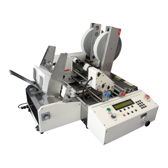
- Page 1 ASTRO ATS-309 MULTI-TABBER/ STAMP AFFIXER OPERATOR MANUAL...
- Page 2 To the best of our knowledge, that information is accurate in all respects. However, neither Astro Machine Corp. nor any of its agents or employees shall be responsible for any inaccuracies contained herein.
-
Page 3: Table Of Contents
TABLE OF CONTENTS TABLE OF CONTENTS SECTION 1 – Getting Acquainted Front View Exit End View Tabber Electrical Connections Feeder and Connections Tabber Control Panel SECTION 2 - Assembly and Installation Assembly Connecting SECTION 3 - Operating Tabber Mechanical Set-up Narrow Media Set-up Running Tri-Fold Long Edge Applying Stamps to #10 Envelopes... - Page 4 Tab Sensor (V-Tab) Adjustment Manual V-Tab Adjustment: Programming Jobs Programming: Tabs with Automatic Setup Programming: Stamps with Manual Setup Placing Multiple Stamps Programming: Tabs on Opposite Sides Programming: Tabs on Perpendicular Sides SECTION 5 – Maintenance Cleaning Rollers and Transport Belts Shafts with Movable Parts Cleaning Sensors Sensor locations:...
-
Page 5: Section 1 - Getting Acquainted
GETTING ACQUAINTED SECTION 1 – Getting Acquainted Front View Control Panel – Control and program Tabber from this panel. Head 1 Fine Tuning Adjustment – Permits fine positioning of tabs on Head 1. Head 2 Fine Tuning Adjustment – Permits fine positioning of tabs on Head 2. Head 1 –... -
Page 6: Exit End View
GETTING ACQUAINTED Exit End View Head 2 Fine Tuning Adjustment – Permits fine positioning of tabs on Head 2. Head 1 Securing Knob – Locks in position of Head 1. Right Media Guide Securing Knob – Locks Right Media Guide in position. Head 1 Transport Belt and Guide –... -
Page 7: Tabber Electrical Connections
GETTING ACQUAINTED Tabber Electrical Connections Emergency Stop Input – When wired into an existing safety circuit, this connector permits an emergency stop from existing circuit to stop Tabber. Jumper Plug is required when this feature is not used. Emergency Stop Output – Permits Tabber to control emergency stopping of another machine. -
Page 8: Feeder And Connections
GETTING ACQUAINTED Feeder and Connections Tabber/Feeder Control Cable – Permits Tabber to control Feeder when Mode Switch is in Automatic position. Power Inlet-Feeder – Power cord plugs in here. Fuse – Feeder fuse is located here. Main Power Switch-Feeder – Turns Feeder ON and OFF. Mode Switch –... -
Page 9: Tabber Control Panel
GETTING ACQUAINTED Tabber Control Panel Transport Power Switch – Turns Tabber transport power ON. NOTE: Transport Power will not activate unless all safety and emergency switches are closed. Speed Control – Adjusts speed of Tabber. NOTE: Maximum speed of Tabber is controlled by software. Tabber speeds for applying tabs: Single tabs to one side of a piece –... -
Page 10: Section 2 - Assembly And Installation
ASSEMBLY AND INSTALLATION SECTION 2 - Assembly and Installation Tabber is shipped in a single carton. Assembly Choose a Location Place Tabber with its Feeder on a sturdy worktable or cabinet at least 12" from any walls. Allow enough room to place Feeder on same work surface. Protect Tabber from excessive heat, dust, and moisture –... -
Page 11: Connecting
ASSEMBLY AND INSTALLATION Install Optional Feeder 1. Pin [A] on Feeder should mate with hole [B] on Tabber body. 2. When Feeder is properly aligned with Tabber body, it looks like picture shown at right. Connecting Plugging in Feeder and Tabber Make sure that Tabber Emergency Stop Switch is turned OFF and Main Power Switch above Power Cord Receptacle is turned OFF. - Page 12 ASSEMBLY AND INSTALLATION CAUTION DO NOT USE ADAPTER PLUGS OR EXTENSION CORDS TO CONNECT TABBER OR FEEDER TO WALL RECEPTACLE. DO NOT USE OUTLETS CONTROLLED BY WALL SWITCHES. DO NOT USE AN OUTLET THAT SHARES SAME CIRCUIT WITH LARGE ELECTRICAL MACHINES OR APPLIANCES. 4.
- Page 13 ASSEMBLY AND INSTALLATION NOTES _____________________________________________________________________________________________ _____________________________________________________________________________________________ _____________________________________________________________________________________________ _____________________________________________________________________________________________ _____________________________________________________________________________________________ _____________________________________________________________________________________________ _____________________________________________________________________________________________ _____________________________________________________________________________________________ _____________________________________________________________________________________________ _____________________________________________________________________________________________ _____________________________________________________________________________________________ _____________________________________________________________________________________________ _____________________________________________________________________________________________ _____________________________________________________________________________________________...
-
Page 14: Section 3 - Operating Tabber
OPERATING TABBER SECTION 3 - Operating Tabber Tabber is capable of applying up to three tabs or stamps on each of two sides of media in one pass. To set-up Tabber for applying tabs or stamps: Determine type of tabbing and number of tabs Determine orientation that media must feed to accommodate application Set-up Tabber and Feeder to feed media Load tabs or stamps in proper Head... - Page 15 OPERATING TABBER 2. Measure width of piece using scale on Tabber. If media width is less than 6.5", Center Support Plate must be removed from Tabber. This is done to allow Right Media Guide to be positioned closer to Left Media Guide.
- Page 16 OPERATING TABBER WARNING! DO NOT MOVE RIGHT-HAND MEDIA GUIDE IF TABBER IS NOT RUNNING. TO DO SO RESULTS IN DAMAGE OR BREAKAGE TO TRANSPORT BELT. 6. Press RUN key and center Speed Control Dial so transport is running at a medium speed. 7.
-
Page 17: Narrow Media Set-Up
OPERATING TABBER Narrow Media Set-up Narrow Media Guide is designed to help you feed media that is less than 5-1/2" and place two side tabs and one end tab on media 5-1/4" wide or more. Guide also permits tabbing long edge of a Tri-Fold and improve Stamp application. -
Page 18: Applying Stamps To #10 Envelopes
OPERATING TABBER Applying Stamps to #10 Envelopes 1. Remove Extra Side Guide from Narrow Media Guide. 2. Set Guide against Envelope. 3. Move Transport Belt Guide against Narrow Media Guide to hold it in place. 4. Set up Head 1 to apply stamps. 5. -
Page 19: Media Thickness Adjustment
OPERATING TABBER Media Thickness Adjustment IMPORTANT TO PERMIT PROPER FEEDING THROUGH TABBER, MEDIA USED TO TAB/STAMP MUST HAVE SQUARE, TIGHT FOLDS, AND BE NEARLY UNIFORMLY THICK. IF MEDIA DOES NOT FEED PROPERLY, IT WILL NOT BE TAB/STAMPED PROPERLY. 1. Close Exit Roller Assembly and lock two latches to secure it. 2. -
Page 20: Adjusting Feeder
OPERATING TABBER Adjusting Feeder Feeder is properly aligned with Tabber when it is installed. Non-operator Side Guide (Right Side) on Feeder is fixed in position for proper alignment of media. Adjust Feeder to feed media: 1. Open non-operator Side Guide to provide room for media. -
Page 21: Setting Media Length
Stamp from lead edge is what is used to determine piece length. In Automatic mode, piece length can be programmed. See Step 15 and 16 in “Programming Tabs with Automatic Setup” in “Programming ATS-309” Section. Loading Tabs (Head 1 or Head 2) -
Page 22: Head 1 Adjustment - General
OPERATING TABBER NOTE: INSTRUCTIONS ABOVE ARE FOR HEAD 2. HEAD 1 IS THREADED IN SAME MANNER. Head 1 Adjustment – General NOTE: Head 1 – apply Tabs to side of a piece, to end of a piece, or to apply Stamps. When loading Tabs or Stamps into Head 1, first determine if you will be tabbing on the side of a piece or tabbing or stamping on the end of a piece. -
Page 23: Head 1 Adjustment - Side Tabbing
OPERATING TABBER Head 1 Adjustment – Side Tabbing Tabber and Feeder should be set-up to feed media before this procedure is used. 1. Unlatch Exit Roller Assembly, swing it open, and then adjust Peel Plate for side tabbing. 2. Lift Tab Drive Pressure Roller Release Latch on Head 1 (to release pressure between tab stock and Tab Drive Roller). - Page 24 OPERATING TABBER 3. Loosen Head Stop and move it toward Head 2 to permit moving Head 1 into position. 4. Pull on backing until a tab starts to protrude from Applicator (peel point). 5. Lower Pressure Roller Release Latch. 6. Refer to picture in Step 4 above, loosen Head 1 Securing Knob and slide Head 1 over Right Media Guide Assembly (as shown).
-
Page 25: Head 1 Adjustment - End Tabbing
OPERATING TABBER IMPORTANT IF YOU HAVE NOT PROGRAMMED TABBER FOR TABBING JOB, REFER TO “PROGRAMMING A JOB” SECTION FOR INSTRUCTIONS. ONCE COMPLETE, RETURN TO THIS PROCEDURE. 8. Release Emergency Stop button. Turn Tabber's Main Power Switch ON. Press Green Transport Power button. Verify that Feeder is still turned OFF. Verify that Feeder Interface Cable is attached between Tabber and Feeder 9. - Page 26 OPERATING TABBER 2. Lift Tab Drive Pressure Roller Release Latch on Head 1, to release pressure between tab stock and Tab Drive Roller. 3. Loosen Head Stop and move it toward Head 2 to permit moving Head 1 into position. 4.
- Page 27 OPERATING TABBER 7. Close Exit Roller Assembly and lock two latches to secure it. IMPORTANT IF TABBER IS NOT PROGRAMMED FOR TABBING JOB, REFER TO “PROGRAMMING A JOB” SECTION FOR INSTRUCTIONS. ONCE COMPLETE, RETURN TO THIS PROCEDURE. 8. Release Emergency Stop button. Turn Tabber Main Power Switch ON. Press Green Transport Power button.
-
Page 28: Head 1 Adjustment - Applying Stamps
OPERATING TABBER Head 1 Adjustment – Applying Stamps NOTE: Head 2 cannot be used to apply stamps. Tabber and Feeder should be set-up to feed media before this procedure is used. IMPORTANT TO AVOID WASTING STAMPS, IT IS STRONGLY SUGGESTED USING TEST STAMPS OR TABS WHEN INITIALLY SETTING UP TABBER FOR APPLYING STAMPS. - Page 29 OPERATING TABBER 4. Loosen Head Stop and move it toward Head 2 to permit moving Head 1 into position. 5. Pull on backing until a stamp starts to protrude from Applicator (peel point). 6. Lower Pressure Roller Release Latch. 7. Refer to picture in Step 4 above, loosen Head 1 Securing Knob and slide Head 1 over Right Media Guide Assembly (as shown).
-
Page 30: Head 2 Adjusting For Side Tabbing
OPERATING TABBER 9. Release Emergency Stop button. Turn Tabber Main Power Switch ON. Press Green Transport Power button. Verify that Feeder is still turned OFF at this time. Verify that Feeder Interface Cable is attached between Tabber and Feeder. 10. Proceed by pressing Operate soft key to put Tabber in OPERATE mode. Screen changes to indicate “Operating Mode”. - Page 31 OPERATING TABBER 2. Lift Tab Drive Pressure Roller Release Latch on Head 2 to release pressure between tab stock and Tab Drive Roller. 3. Pull on backing until tab starts to protrude from Applicator (peel point). 4. Lower Pressure Roller Release Latch. NOTE: Image in Step 3 shows how center point of tab should align with exit end of Left Media Guide Assembly.
-
Page 32: Operating Tabber
OPERATING TABBER 6. Release Emergency Stop Button. Turn Tabber Main Power Switch ON. Press Green Transport Power Button. Verify that Feeder is still turned OFF at this time. Verify that Feeder Interface Cable is attached between Tabber and Feeder. IMPORTANT IF ONLY USING HEAD 2, MAKE SURE THAT HEAD 1 IS DISABLED IN SOFTWARE. -
Page 33: Understanding Start-Up Screen
OPERATING TABBER 5. Press STOP key [7] (located below soft keys) to stop Tabber. Pressing large Emergency Stop button [5] shuts down entire Tabber and locks out other keys. To restart from an Emergency Stop, release button by turning it clockwise. Then press RUN key [8] to restart Tabber. -
Page 34: Exceeding Tabbing Rate
OPERATING TABBER c. Rate or speed in pieces per hour. d. Number of Pieces that have been run. This can be reset by pressing CLEAR key on Control Panel before starting job. Operation of Tabber is the same whether you are tabbing or applying stamps. Refer to the parts of this section regarding setting up Tabber for the type of application you are performing for more information. - Page 35 OPERATING TABBER 2. Select Job you wish to run. (In this example, we are selecting Job #2 using soft key 2.) 3. When you press Job # soft key this screen appears. Press RUN key on Control Panel to start Tabber. NOTE: To check setup, press and hold INFO key on Tabber Control Panel.
-
Page 36: Fine Tuning Adjustments
OPERATING TABBER Fine Tuning Adjustments Once Tabber is programmed for a job it may be necessary to fine tune settings for optimum performance. Any job in memory can be modified or changed at any time before or during operation. Memory is non-volatile in that once a job is programmed, turning machine OFF or disconnecting it from its electrical source will not erase memory. -
Page 37: Head 1 Side Tab Adjustment
OPERATING TABBER Head 1 Side Tab Adjustment Due to differences in thickness of a piece it may be necessary to fine tune position of tab on piece. To do this, a mechanical adjustment is required for each head that requires adjustment. Adjusting knobs are located near Head 1 on operator’s side of Tabber. -
Page 38: Head 2 Side Tab Adjustment
OPERATING TABBER Adjusting tabs' position across length of lead edge is done with Knob 1. Turn knob counterclockwise to move tab to the right and clockwise to move tab to the left of lead edge. NOTE: When adjusting tab position, make sure tab does not move out of the window, as this will cause tab to jam. - Page 39 OPERATING TABBER NOTES _____________________________________________________________________________________________ _____________________________________________________________________________________________ _____________________________________________________________________________________________ _____________________________________________________________________________________________ _____________________________________________________________________________________________ _____________________________________________________________________________________________ _____________________________________________________________________________________________ _____________________________________________________________________________________________ _____________________________________________________________________________________________ _____________________________________________________________________________________________ _____________________________________________________________________________________________ _____________________________________________________________________________________________ _____________________________________________________________________________________________ _____________________________________________________________________________________________...
-
Page 40: Section 4- Programming Tabber
PROGRAMMING THE TABBER SECTION 4- Programming Tabber Notes before Programming Two methods for programming jobs on Tabber: 1. Automatic – Tabber is given tab information and it automatically sets up location of tab or tabs by automatically measuring piece. 2. Manual – Operator specifies tab positioning. In either case, some operator interaction to fine tune tab location and feed media through Tabber may be required. -
Page 41: Job
PROGRAMMING THE TABBER Version Version soft key displays this screen: LIFETIME PRODUCTS: Total number of pieces transported through system. Total number of tabs/stamps applied by each Head LIFETIME TABS: (Head1, Head2) BIOS Version: Software version that is currently loaded into Tabber. BACK: Returns you to Advanced features screen. -
Page 42: Manual Tab/Stamp Positioning Features
PROGRAMMING THE TABBER Manual Tab/Stamp Positioning Features Pressing Manual soft key from “Select Setup Option” screen puts Tabber into “manual positioning mode”. In this mode, the operator must manually set offset value (position) for each tab/stamp being applied. From “Select Tabber Head” screen, select Head you want to set up. -
Page 43: Head #2
PROGRAMMING THE TABBER If Tab/Stamp or Side Tab is selected, the following choices appear. # Tabs – Select to set number of tabs or stamps you would like to apply to media with selected Head. Position – Select to set position (offset values) for each tab/stamp to be applied to media with selected Head. -
Page 44: Head #1
PROGRAMMING THE TABBER Head #1: If you select 1 for # Tabs, “Select Option to edit” screen reappears. Separate – Allows individual adjustment of each tab/stamp position via Offset Value. Together – Tabs/Stamps placed next to each other, starting at Offset Value set for Tab 1. BACK –... -
Page 45: Pitch
PROGRAMMING THE TABBER IMPORTANT TAB/STAMP POSITION IS BASED ON PLACEMENT OF BEGINNING OFTAB/STAMP WITH RESPECT TO LEAD EDGE OF PIECE. WHEN PLACING TABS/STAMPS, LENGTH OF TAB IS NOT CALCULATED. Pitch Pitch is very important. Pitch setting is how software determines how far to advance tab. If Pitch soft key is pressed, display prompts you to “Enter Tab Pitch and press SAVE key”. -
Page 46: Automatic Tab Positioning Features
PROGRAMMING THE TABBER Automatic Tab Positioning Features When Automatic soft key is pressed, display prompts you to select which Head to set up. NOTE: This feature can be used to position tabs automatically when “side tabbing”. Positions are based on product length and number of tabs selected. - Page 47 PROGRAMMING THE TABBER Selecting Side Tab provides following choices: # Tabs – Select to choose number of tabs to apply to media with selected Head. Product-L – Select to set paper length of media you are using. Pitch – Select to set tab pitch (distance from top of one tab/stamp, to top of next tab/stamp) for tab/stamp stock used on selected Head.
-
Page 48: Manual Product Length Input
PROGRAMMING THE TABBER When Automatic soft key is pressed, display may prompt you to “Increase Transport Speed” or “Decrease Transport Speed”. Adjust transport speed until display shows “Feed 1 Product now”. When display reads “Feed 1 Product now”, feed one of your mail pieces through Tabber. NOTE: Feeding more than one piece causes an incorrect length to be measured and set. -
Page 49: Tab Sensor (V-Tab) Adjustment
PROGRAMMING THE TABBER Tab Sensor (V-Tab) Adjustment Every time a new tab/stamp stock is used or a new job is set up, you must also set up Tab Sensors for that tab/stamp stock. NOTE: To avoid wasting stamps, it is strongly suggested to manually program V-Tab voltages, instead of using Automatic feature. - Page 50 PROGRAMMING THE TABBER “Select Tab before calibration” screen appears. Select type of tab, either Opaque or Clear, based on table below. For this example, select Opaque. TAB TYPE SELECT Tabs in which space between tabs is Opaque lighter than tab even if tab is white. Tabs that have a black line between tabs.
-
Page 51: Manual V-Tab Adjustment
PROGRAMMING THE TABBER Manual V-Tab Adjustment: 1. Open Exit Roller Assembly. 2. Begin programming by selecting Job# with soft key under display. 3. Select Job # to use for job. (This example uses Job # 2.) 4. From Select Setup Option screen, Select V-Tab. -
Page 52: Programming Jobs
PROGRAMMING THE TABBER Tab Type Description Gap V Level Tab V Level Tabs in which space between tabs is lighter Opaque High than the tab even if tab is white. Clear Tabs that have a black line between tabs. High IMPORTANT WHEN SETTING GAP VOLTAGE AND TAB VOLTAGE MANUALLY, SOFTWARE DETERMINES IF TAB TYPE IS OPAQUE OR CLEAR, BASED ON... -
Page 53: Programming: Tabs With Automatic Setup
PROGRAMMING THE TABBER Programming: Tabs with Automatic Setup NOTE: If piece that is being tabbed is less than 5" wide, refer to section on Narrow Media for information on how to set up for narrow media. In example above, we use only one Tab Head, Tab Head 2. Begin by deciding if there will be one, two or three tabs on media. - Page 54 PROGRAMMING THE TABBER IMPORTANT FEEDER MODE SWITCH SHOULD BE SET TO MANUAL 4. Next screen allows you to select Head you are using to tab. (This example uses Head 2, so select V-Tab 2.) 5. Next select Automatic from “Tab Sensor 2 setup” screen. 6.
- Page 55 PROGRAMMING THE TABBER 8. On “Select Setup Option” screen select Automatic. 9. Next screen tells Tabber how many Heads will be used for job. Select Head #1 first so that we can turn it off as follows: 10. “Select option to edit” screen appears.
- Page 56 PROGRAMMING THE TABBER 13. From this screen select # Tabs. 14. In this example, we are going to apply two tabs to the piece. Select 2. 15. Program will automatically return to “Select option to edit, or” screen. Select Product-L. 16.
- Page 57 PROGRAMMING THE TABBER 17. Press BACK until you return to “Select Tabber Head #1 or 2 to setup” screen. Then press RUN on Control Panel to run job. NOTE: By running Tabber from this “Select Tabber Head” screen rather than start screen you can access either Head to make small adjustments in tab’s location on piece without going through start-up screens.
-
Page 58: Programming: Stamps With Manual Setup
PROGRAMMING THE TABBER Programming: Stamps with Manual Setup NOTE: If piece being stamped is less than 5" wide, refer to section on Narrow Media for information on how to set up for narrow media. IMPORTANT BEFORE ATTEMPTING TO PROGRAM ANY JOB, SET UP FEEDER AND TABBER TO FEED MEDIA. - Page 59 PROGRAMMING THE TABBER 3. Before setting up job, set up Tabber Sensors to read stamp. Select V-Tab and follow instructions. 4. Next screen allows you to select Head you are using to tab. (This example uses Head 1, so select V-Tab 1.) 5.
- Page 60 PROGRAMMING THE TABBER 7. Next screen tells Tabber how many Heads will be used for job. Select Head #2 first so we can turn it OFF as follows: 8. “Select option to edit” screen appears. Select None and “Select Setup Option” screen reappears. 9.
- Page 61 PROGRAMMING THE TABBER 12. In this example we are going to apply one stamp. Press 1. 13. Select Pitch when “Select option to edit” screen appears. NOTE: Whether programming manually or automatically, set Pitch manually to ensure good registration of stamp. 14.
-
Page 62: Placing Multiple Stamps
PROGRAMMING THE TABBER 17. Software returns to “Select option to edit” screen. From here you can press RUN on Control Panel, run a sample and check for proper placement of stamp. If adjustments are required, see “Fine Tuning Adjustments” at end of this Section. Placing Multiple Stamps 1. -
Page 63: Programming: Tabs On Opposite Sides
PROGRAMMING THE TABBER Programming: Tabs on Opposite Sides Tabber is designed to perform tabbing operations according to latest USPS regulations for booklets in addition to stamp affixing and tabbing of other material. Before setting up Tabber you must determine required method of tabbing. All material to be tabbed must have good tight folds to permit feeding through Tabber. - Page 64 PROGRAMMING THE TABBER 1. Begin by selecting Job # from “Press Run to tab” screen. 2. Then select Job # 3 from “Select saved Job#” screen. 3. Before you can set up job you must set up Tabber Sensors to read tab. Select V-Tab and follow instructions.
- Page 65 PROGRAMMING THE TABBER Tab Type Description Gap V Level Tab V Level Tabs in which space between tabs is lighter Opaque High than tab even if tab is white. Clear Tabs that have a black line between tabs. High NOTE: When setting Gap Voltage and Tab Voltage manually, software determines if Tab Type is Opaque or Clear based on voltage readings.
- Page 66 PROGRAMMING THE TABBER 10. Pitch of tab is distance measured from top of one tab to top of next tab. This is done by selecting Pitch from “Select option to edit” screen. Measure distance from top of one tab to top of next tab.
- Page 67 PROGRAMMING THE TABBER 14. Select Tab 2 and enter position for Tab 2 from lead edge. This tab should be positioned at a distance of less than 1" from trailing edge of piece. If piece is 8.0" long and you are using 1-1/2" tabs as required, setting would be 1.500"...
- Page 68 PROGRAMMING THE TABBER IMPORTANT WHEN SELECTING HEAD 1 REFER TO SECTION “ADJUSTING TAB POSITION”, STEP 5 TO INSURE TAB SEPARATOR IS SET PROPERLY 19. “Select option to edit” screen for Head 1 is different from Head 2. Select Tab/Stamp option as we are going to place a tab on side opposite of Head 2.
-
Page 69: Programming: Tabs On Perpendicular Sides
PROGRAMMING THE TABBER Programming: Tabs on Perpendicular Sides Tabber is designed to perform tabbing operations according to latest USPS regulations for booklets in addition to stamp affixing and tabbing of other material. Before setting up Tabber, determine required method of tabbing. All material to be tabbed must have good tight folds to permit feeding through Tabber. - Page 70 PROGRAMMING THE TABBER 2. Then select Job # 4 from “Select saved Job#” screen. 3. Before you can set up Job, you must set up Tabber Sensors to read tab. Select V-Tab and follow instructions. 4. Next screen allows you to select Head that you are using to tab.
- Page 71 PROGRAMMING THE TABBER 6. Then press BACK until you return to “Select Setup Option” screen and select Manual. 7. Select Head 2, then select Side Tab. 8. Then select # Tabs, and on next screen, select 2. 9. Select Pitch when “Select option to edit”...
- Page 72 PROGRAMMING THE TABBER 11. Press BACK one time to return to “Select option to edit” screen and select Position. 12. Each of the two tab positions must be entered. Position of tab is measured from lead edge of piece (exit end) separately.
- Page 73 PROGRAMMING THE TABBER 16. Then select V-Tab 1. Follow Step 5 and calibrate V-Tab voltage for Head 1. 17. Then return to “Select Tabber Head” screen and Select Head 1. IMPORTANT WHEN SELECTING HEAD 1, REFER TO SECTION “ADJUSTING TAB POSITION”, STEP 5 TO INSURE TAB SEPARATOR IS SET PROPERLY 18.
- Page 74 PROGRAMMING THE TABBER 20. When you select Front Tab, positioning screen appears. If piece is 1/8" thick or more you can pre-adjust tab position by using arrows. Moving line toward right puts more of tab on bottom of piece. Moving it to left puts more of tab on top of piece.
- Page 75 PROGRAMMING THE TABBER NOTES _____________________________________________________________________________________________ _____________________________________________________________________________________________ _____________________________________________________________________________________________ _____________________________________________________________________________________________ _____________________________________________________________________________________________ _____________________________________________________________________________________________ _____________________________________________________________________________________________ _____________________________________________________________________________________________ _____________________________________________________________________________________________ _____________________________________________________________________________________________ _____________________________________________________________________________________________ _____________________________________________________________________________________________ _____________________________________________________________________________________________ _____________________________________________________________________________________________...
-
Page 76: Section 5 - Maintenance
MAINTENANCE SECTION 5 – Maintenance This section describes maintenance that an experienced operator can perform. If any service or maintenance is required beyond that which is described in this document, please contact your local dealer. Cleaning WARNING! TABBER AND FEEDER ARE PRECISION MACHINES THAT SHOULD BE CLEANED REGULARLY TO INSURE MANY YEARS OF SERVICE. -
Page 77: Cleaning Sensors
MAINTENANCE Cleaning Sensors There are three Sensors in Tabber: Two Tab Sensors – one on each Applicator Head and one Media Sensor located on Head 2 Transport Belt Assembly. These Sensors should be clean and free of accumulated paper dust. Use dry compressed air to remove the dust. WARNING! DO NOT USE ABRASIVES OF ANY KIND ON SENSOR LENSES. -
Page 78: Tab Sensor Test
MAINTENANCE Tab Sensor Test Use "V-Tab adjustment" screen to check live tab sensor voltage (V=) value. 1. Not Interrupted (Nothing in Sensor, Tab stock removed.) 0.12V or less. 2. Tab Sensor reads higher than 0.12V, even though you removed all tab material from Tab Applicator and cleaned Tab Sensor: indicates a dirty or damaged Sensor. -
Page 79: Lubrication
MAINTENANCE Lubrication WARNING! TABBER AND FEEDER ARE PRECISION MACHINES THAT SHOULD BE CLEANED REGULARLY TO INSURE MANY YEARS OF SERVICE. BEFORE PERFORMING ANY MAINTENANCE, DISCONNECT MACHINES FROM THEIR POWER SOURCES! Several locations on Tabber require regular lubrication: 1. Place a small amount of white lithium grease on surfaces where Head Assembly raises and lowers. -
Page 80: Section 6 - Troubleshooting
TROUBLESHOOTING SECTION 6 – Troubleshooting Troubleshooting Guide is provided to assist you in solving any problems that might occur with Tabber. We tried to make it as complete as possible. The best advice we can offer is to make sure that tabs, labels or stamps are threaded properly and that machine is plugged in and turned ON. -
Page 81: Tab Placement Problems
TROUBLESHOOTING Tab Placement Problems CONDITION SOLUTION Tabs are not placed in same spot on media. Tabs should be placed within +/- 1/8" 1. Check Pitch setting for tab. It should be slightly more than tab size plus space between tabs. 2. - Page 82 TROUBLESHOOTING Tab Placement Problems (continued) CONDITION SOLUTION Lead edge tab is more on top than bottom This adjustment is performed by software. See “Head 1 Tabbing at the Lead Edge of a Piece” in Operating Instruction Section. Tab is not flush with edge of media. Media is not being fed flush with Fixed Side Guide.
-
Page 83: Stamp Placement Problems
TROUBLESHOOTING Stamp Placement Problems CONDITION SOLUTION Stamps are not placed in same place Stamp placement should be within +/-1/8". on media. 1. Check Pitch setting for stamp. It should be slightly more than stamp size plus space between stamps. 2. Check amount of Head pressure. Too little can cause media to slip when it is being fed. -
Page 84: Tabber Operation Problems
TROUBLESHOOTING Tabber Operation Problems CONDITION SOLUTION Tabber flashes "Exceeding Tabbing Rate" 1. Speed of tabbing exceeds maximum warning while tabbing. speed for number of tabs being applied. Slow Tabber. 2. Feeder speed is too fast, leaving too little gap between pieces. Slow down Feeder or use optional Feeder connected to Tabber. - Page 85 TROUBLESHOOTING 2. Encoder Test – Tests if Encoder is working. When you click on Test ON, a number displays in “Reading:” Rotate Exit Roller, if number changes, Encoder is working. Click Next to go to next test. IMPORTANT REMOVE TABS FROM BOTH HEADS FOR REMAINING TESTS. 3.
- Page 86 TROUBLESHOOTING 4. Head #1 Tab Sensor – Tests that Tab Sensor in Head # 1 is working. Test should be conducted with tabs removed from Tabber. A piece of paper inserted into Sensor should change display from UNCOVERED to COVERED. Press Next to proceed to Head # 2 Tab Sensor test.
-
Page 87: Appendix A - Specifications
APPENDIX Appendix A – Specifications ONE PASS TAB: 1-3 per side or 1-3 on 1 side and 1 front Minimum: 3/4" STANDARD TAB: Maximum 1-1/2" STAMPS: 1 to 3 Minimum (Single-Side Tabbing): 3.25" x 5" MEDIA SIZE (L x W): Minimum (Two-Side Tabbing): 6.5"... -
Page 88: Appendix B - Identifying Tab Types
APPENDIX Appendix B – Identifying Tab Types The following images will help you identify which Tab Type (Opaque or Clear) to select when using the Automatic V-Tab feature. Tab Type – Opaque Stock that has white space/line (white gap) between each tab/stamp. Tab Material: Clear or Translucent Backing: Black Box under tab area. -
Page 89: Appendix C - Tab Placement Capabilities
APPENDIX Appendix C – Tab Placement Capabilities These images will help you identify what Tab positioning is possible when setting up the Tabber. KEY: Head #1 in “Side Tabbing” Mode: NOTE: Time required to switch between Modes – 20 seconds. Head #1 in “Front Tabbing”... - Page 90 APPENDIX TABBER SETUP #1: JOB TEMPLATES:...
- Page 91 APPENDIX TABBER SETUP #2: JOB TEMPLATES:...
- Page 92 APPENDIX TABBER SETUP #3: JOB TEMPLATES:...
- Page 93 APPENDIX TABBER SETUP #4: JOB TEMPLATES:...
- Page 94 APPENDIX TABBER SETUP #5: JOB TEMPLATES:...
-
Page 95: Index
INDEX Index Adjustments Diagnostics ............37, 80 Applying Stamps, Head 1 ........24 Display, Tabber ............5 Backlight .............. 36 End Tabbing, Head 1 ........... 21 Electrical Connections ..........3 Feeder ..............16 Emergency Stop ............5 Fine Tuning ............32 Input ............... - Page 96 INDEX Identifying Tab Types ..........84 Reel Supports ............. 6 Info Key ..............5 Reels, Take-up ............1 Install Rollers Feeder ..............7 Cleaning ............... 72 Reel Supports ............6 Exit Pressure ............2 Run Key ..............5 Jams ................. 76 Job # Soft Key ............
- Page 97 INDEX Emergency Stop ............. 5 Troubleshooting ............. 76 Emergency Stop Input ........... 3 Jams ..............76 Emergency Stop Output ......... 3 Operation Problems ..........80 Exceeding Tabbing Rate ........30 Stamp Placement Problems ......... 79 Exit Foot ..............2 Tab Placement Problems ........77 Exit Foot Knob ............
- Page 100 Copyright 2015 All rights reserved 05/20/2015 Part Number: 100-ATS-309 Rev. G...
Need help?
Do you have a question about the ATS-309 and is the answer not in the manual?
Questions and answers