
Subscribe to Our Youtube Channel
Related Manuals for ASTRO V16


Summary of Contents for ASTRO V16
-
Page 1: Must Be Observed: Hazard And Safety Information
Slot 1 Slot 2 Slot 3 Slot 4 Slot 5 Slot 6 Slot 7 Slot 8 Power A Power B SAT HEADEND... -
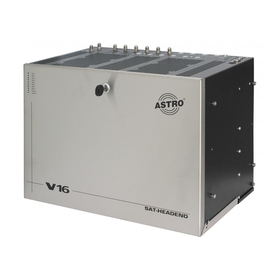
Page 2: Figure Of V16
V16 Base Unit without Cards Bus adapter LED indicator lamps Interlocking device 2 temperature regulated fans SAT distribution board Slots Redundant power supply The V16 is CE certified and complies with all relevant EN standards. Changes and printing errors reserved. Version: 02 / 2009. -
Page 3: Table Of Contents
If you have any questions about waste 4 Configuration of V16 and VMS 616 ....disposal, your local environmental agency would be glad 4.1 Setting VMS 616 mode . -
Page 4: Opening The Housing
Warning: When the device is installed in places such as the device to ASTRO with an exact description of the fault. storage areas and roof trusses, it must be ensured that the Replace the power cables only with an original part power permitted ambient temperature is maintained. -
Page 5: Main Connection
Main connection If a SAT VMS 616 distribution board is to be subsequently installed to a V16 base or an already installed VMS 616 is to be removed, the change must be set in the software of the During operation the V16-type appliance (protection base device. -
Page 6: Lnb Remote Supply (For Vms 616)
3 Preparing the base unit The power supply unit (power If in a V16 base a single power unit (VSN 1) is to be sub- sequently exchanged for a redundant one (VSN 2) or vice supply carrier) is secured with... -
Page 7: 3.5 Remote Supply Voltage On Hf Output
3.5 Remote supply voltage on HF output V16 Parameter If an ASTRO network (U901 or VZN9) is employed Select the next menu with the arrow key. The V16 VMS -Inputs 11-14 for the active signal consolidation of multiple V16s, parameters are displayed. -
Page 8: Setting Bus Address
(VMS inputs 11-16). This setting can also be made with the ASTRO HE (Itʼs a good idea to place the bar on top of the V16 while programming software. the card is being installed. The connection labels speed up correctly assigning, for example, the SAT inputs. -
Page 9: Cards With Sat Tuner (Sat Distribution Board Vsf 8)
5 Installing plug-in cards 5 Installing plug-in cards Single cards Plug in the card. Connect the tuner A connection cable to Plug in the card. Connect the tuner connection cable to an available output of the SAT VSF 8 distribution board the corresponding output A of the SAT VMS 616 distri- that carries the required polarization. -
Page 10: Uninstalling Plug-In Cards
V16, (de-) modula- tor cards (X-twin AV and X-twin demod) should be On the front side of the V16 base device are 10 two-color Slot 1 installed at slot 1 or 2. -
Page 11: Level Adjustment
7 Indicators (front LEDs) 8 Level adjustment Level adjustment Slot 1 Slot 2 Power A green LED The optimal output level (measured at the output of the Slot 3 base device) is as follows: Slot 4 Power B red LED: Power supply A in operation •... -
Page 12: Technical Specifications
340 x 491 x 290 + 3 HE for air flow unit Weight of V16.1 base unit [kg] V 16 + VSN VSN 1 power supply / VSN 2 redundant power supply power supply plug-in unit... -
Page 13: Accessories
VAF Air Flow Unit Luftableitblech zur optimalen Wärmeableitung der V16 bei 19” Montage (Best.-Nr. 380 980) VH 5 (order no. 380 250) Adapter panel for accommodating up to five VSF 8 / VSF 42 (order no. 380 980) Air flow unit for optimizing heat dissipation of the V16 with 19” installation... - Page 14 Accessories X-BC … Buscontroller X- BC 1 The headend bus controller is for centrally setting all bus-capable headend devices via PC. Maintenance and re-programming of already set up headends can be done via modem. Operation is only possible with the HE programming software! X- BC 1 Control of up to 240 bus-capable headend devices Can be individually set, from ring tone to call reception (i.e.
- Page 15 HE programming software The HE programming software (order no. 330 630) facilitates programming X-5/X- 8/V16 headend systems with a PC or laptop computer. The user can store all head- end parameters in the office prior to commissioning, for example: received satellite...
- Page 16 ASTRO Strobel Kommunikationssysteme GmbH Olefant 1–3 D-51427 Bergisch Gladbach (Bensberg) Tel. +49 (0 ) 22 04 / 405-0 Fax +49 (0 ) 22 04 / 405 10 e-mail: kontakt@astro-kom.de http://www.astro-kom.de Germany...
Need help?
Do you have a question about the V16 and is the answer not in the manual?
Questions and answers